Journal of Computer and Communications
Vol.07 No.07(2019), Article ID:94046,8 pages
10.4236/jcc.2019.77024
GF-5 VIMI On-Orbit Calibration Instrument and Performance
Hao Wang
Beijing Institute of Space Mechanics & Electricity, Beijing, China


Received: April 12, 2019; Accepted: July 28, 2019; Published: July 31, 2019
ABSTRACT
The Visible and Infrared Multispectral Imager (VIMI) is one of the main payloads of the GF-5 satellite. It has 12 spectral bands covering the wavelength from visible light to thermal infrared. The imager designed life is 8 years. In order to monitor and correct the radiometric performance of the imager for a long time and meet the user’s demand for the quantitative remote sensing application, the expandable diffuser used for calibration in full FOV and full optical path method is designed. The solar diffuser is installed on the front side of the optical system and does not affect the normal imaging of VIMI. When VIMI need calibration, the diffuser is expand to the front of optical system via the driving mechanism. According to the characteristics of the GF-5 satellite orbit, the requirement of the calibration energy and the installation matrix of the imager relative to the satellite, the expansion angle of the diffuser is 39 degrees. The 430 mm × 430 mm large-size PTEE diffuser is manufactured to ensure full FOV and full optical path calibration. The diffuser’s directional hemispherical reflectance is higher than 95% from 420 nm to 2400 nm and variation of BRDF in the direction of imager observation is better than 2.5%. The diffuser stability monitoring radiometer is designed to monitor the on-orbit attenuation performance of the diffuser. Results of ground simulation experiments and preliminary on-board calibration experiments were introduced.
Keywords:
On-Orbit Calibration, Solar Diffuser, Radiometric Calibration, GF-5 Satellite

1. Introduction
GF-5 is a high-spectral satellite of China’s high-resolution earth observation system. The visible infrared multi-spectral imager (VIMI) built by Beijing Institute of Space Mechanics & Electricity (BISME) is one of the main loads of the GF-5 satellite running in the sun-synchronous orbit (1:30 pm ascending northwards) launched in May 9, 2018. VIMI has a swatch width of 60 km and makes observation in12 spectral bands covering the spectrum from 0.45 to 12.5 μm at two nadir spatial resolutions of 20 m (bands 1 - 6), and 40 m (bands 7 - 12), as shown in Table 1.
According to the characteristics of VIMI, such as multi-band, high resolution (large aperture of optical system), long life and high calibration accuracy, we have investigated high quantification payloads such as MTI [1] [2], MODIS [3] [4], VIIRS [5] [6] and OLI [7] [8] and designed a large-scale solar diffuser(SD) and solar diffuses stability monitor (SDSM) to fulfill all optical path and all field of view or-orbit radiation calibration. Part II briefly introduces the on-board calibration instrument. Part III shows the results of ground simulation experiment. Part IV presents the preliminary on-board calibration performance and results.
2. Overview of On-Board Calibration Schemes and Instruments
The GF-5 satellite operates in solar synchronous orbit with an orbit altitude of 705 km. In order to reduce the effect of radiation from earth during radiometric calibration [9] [10], the absolute radiometric calibration of VIMI B1-B6 band is executed after the GF-5 satellite enters the full illumination area from the penumbra near the Antarctic sky (EF arc in Figure 1).
The calibration instrument is mainly composed of SD, SDSM and SD driving mechanism (SDDM). The SDDM includes a stepping motor, gear reduction unit, emergency components, etc. The three-dimensional model is shown in Figure 2. Before calibration, the gear reduction unit with a transmission ratio of 8:1 is driven by the stepping motor, then the SD is driven to rotate. The SD

Table 1. Some parameters of VIMI.

Figure 1. Schematic diagram of the opportunity for calibration.
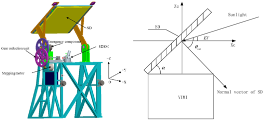
Figure 2. The calibration instruments and the spreading angle.
reaches the designated position via counterclockwise rotation around the Y axis from the +X axis to +Z axis in the imager coordinate system. The reflected sunlight from the SD is introduced into the optical system. According to the pupil radiance and the output digital number (DN) of the imager establishes calibration equation. At the same time, the bidirectional reflectance distribution function (BRDF) attenuation of SD is monitored and corrected by SDSM. At the end of calibration, the SD is return to the original location, and the imager imaging optic path is not interrupted. The SD is protected in the receiving device from ultraviolet radiation, high-energy particle bombardment and satellite gas pollution. If the SD can’t return to the initial position at the end of calibration causing the imaging optic path is interrupted, the emergency component of the SD is activated, so that the driving gear of the SDDM is detached, and the SD automatically returns to the initial position under the action of coiling spring, and then on-orbit SD calibration is no longer carried out.
During on-orbit SD calibration, the spreading angle α of SD is 39 degree, solar zenith angle is ranging from 76 degree to 66degree. In order to realize the calibration of all-optical path and all-field-of-view, the SD size is 430 mm × 430 mm .The scale of SD can calculate based on simple geometric relationship according to the imager field of view and the distance between the SD and the primary mirror size. The materials of SD are polytetrafluoroethylene (PTFE) with high diffuse reflectance, flat spectrum, high Lambert and stable on-orbit performance. Figure 3 shows the DHR of the calibrated SD measured in laboratory.

Figure 3. Directional hemispherical reflectance (DHR).
The reflectance of the SD is higher than 95% in the 420 - 2400 nm spectral region, and the spectrum is flat.
The Lambert property of SD is tested in laboratory. As shown in Figure 4, only the BRDF of B1 and B2 bands at imager observation angle is given here. The BRDF change of SD in use angle is less than 2.5% indicated its good Lambert property.
The SDSM directly monitors the attenuation of SD in B1, B3, B4 and B5 bands. The attenuation in B2 and B6 bands is obtained indirectly from the attenuation data of known bands. The solar irradiance/SD reflectance radiance can be observed by the SDSM through the shutter switch controlled by the solenoid valve. The SD and SDSM are shown in Figure 5. The attenuation of BRDF of SD is corrected by the signal ratio of solar irradiance and SD reflectance radiance and its historical data comparison.
The relationship between the attenuation and the output DN of SDSM is as follows.
where are the observed values of SD and sun by SDSM after dark current is subtracted respectively. are the cosine correction factors of SDSM at t and time respectively.
3. Ground Simulate On-Orbit Calibration
In order to verify the calibration efficiency of SD on orbit, simulation experiment is carried out on the ground using solar simulator. The solar simulator (SSM) collimates the beam outgoing, and the opening size is ≥Φ450 mm, which ensures that the beam can cover the SD completely, as shown in Figure 6.
The radiation emittance of SSM is set to 0.8, 0.5, 0.3 and 0.1 solar constant (SC). The imaging parameters of VIMI are set and the output DN is recorded. The measurement results are shown in Table 2. Figure 7 shows the relationship of output DN of B1 and B6 band with SC.
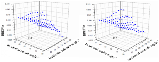
Figure 4. BRDF of the diffuser.


Figure 5. SD and SDSM.

Figure 6. Ground simulate on-orbit calibration.

Figure 7. The DN value of VIMI changing with the solar constant.
4. On-Orbit Calibration Performance
The first on-orbit SD calibration was carried out for the full spectral imager VIMI on August 28, 2018, and the site calibration was carried out over the Dunhuang site on September 11, 2018. For the same region as shown in Figure 8, the two calibration results were compared. As shown is Table 3, the results of two calibration methods have good consistency except B4 and B6 band.
Since launched from May 9, 2018, several times on-orbit calibration experiments have been carried out and SDSM monitored the stability of SD and obtained calibration coefficients at different time as shown in Figure 9.
It can be seen from the figure that the SD has no obvious attenuation and the calibration coefficient is relatively stable, but with seasonal fluctuations. It may be caused by the different incidence angle of the sunlight causing the different stray light in different seasons.
Table 2. Output digital signal under different imaging parameters.
Table 3. The comparison of two calibration results.

Figure 8. The region used for comparison.

Figure 9. The calibration coefficients at different time.
5. Conclusion
This paper introduces the GF-5 VIMI’s on-orbit solar calibration method and the design of calibration instruments, including SD, the emergency exit design of SD and SDSM et al. The ground simulation experiment and on-orbit calibration performance are introduced. The results show that the SD has no obvious attenuation and the calibration coefficient is relatively stable, but with seasonal fluctuations. This phenomenon may be caused by stray light. Follow-up work need to collect more monitoring results to determine whether the variation changing periodically with the season certainly. If it is determined that need to establish the model of stray light changing with illumination and observation angle to improve the accuracy of attenuation monitoring and absolute calibration.
Conflicts of Interest
The author declares no conflicts of interest regarding the publication of this paper.
Cite this paper
Wang, H. (2019) GF-5 VIMI On-Orbit Calibration Instrument and Performance. Journal of Computer and Communications, 7, 293-300. https://doi.org/10.4236/jcc.2019.77024
References
- 1. Chang, S.T., Sun, Z.Y. and Zhang, Y.Y. (2014) Radiation Measurement of Small Targets Based on PSF. Optics and Precision Engineering, 22, 2879-2887.
- 2. Fo, X.C. and Fan, H.S. (2009) Analysis of Detection Capability of the Space Tracking and Surveillance System. Journal of Detection & Control, 31, 49-53.
- 3. Watson, J. and Zondervan, K. (2008) The Missile Defense Agency’s Space Tracking and Surveillance System. Proceedings of SPIE Sensors, Systems, and Next-Generation Satellites XII, 7106, 710617-1-710617-7. https://doi.org/10.1117/12.801937
- 4. Yang, Y., Wu, Z.S. and Yao, L.X. (2002) Method of Calculating the Radiance of Point-Source Target in Infrared Image. International Journal of Infrared and Millimeter Waves, 23, 1347-1355.
- 5. Cao, L.H., Wan, C.M. and Zhang, Y.F. (2015,) Infared Radiation Characteristic Measure Method of Point Target. Infrared Millim. Waves, 34, 460-464.
- 6. Cui, W.Y., Chen, C. and Yi, W.N. (2015) Radiation Characteristic Inversion of Space Point Source Target Based on Infrared Imagery. SPIE Vol. 9674, Optical and Optoelectronic Sensing and Imaging Technology. https://doi.org/10.1117/12.2202923
- 7. Wang, H., Wang, H.Y. and Lian, M.L. (2017) Effect of FFT on Knife-Edge Measurements of MTF. Spacecraft Recovery & Remote Sensing, 38, 61-68.
- 8. Wang, S., Zhang, Y.Q. and Sun, B.Y. (2016) Review of Point Target Tracking Methods Based on Infrared Sensor. Modern Defence Technology, 44, 124-134.
- 9. Tian, Y.X., Gao, K. and Liu, Y. (2016) A Novel Multi-Band Infrared Mutation Point Target Detection Method Based on Generalized Cumulative Sum. Infrared and Laser Engineering, 45, 0526001-1-0526001-7. https://doi.org/10.3788/irla201645.0526001
- 10. Zhuang, X.X., Ruan, N.J. and Zhao, S. (2016) Characterization Techniques of Space Objects Based on Point Target Information. Infrared and Laser Engineering, 45, S126001-1-S126001-6.