 Journal of Biomaterials and Nanobiotechnology, 2011, 2, 601-613 doi:10.4236/jbnb.2011.225072 Published Online December 2011 (http://www.scirp.org/journal/jbnb) Copyright © 2011 SciRes. JBNB 601 As Could We Assure Safety in Large Scale Manufacturing of Nanoparticles for Biomedical Applications Kirill Serguey Maksimov1, Serguei Kirillovich Maksimov1, Nikolay Dmitrievich Soukhov2 1Laboratory of Electron Microscopy, National Research University of Electronic Technology, Moscow, Russia; 2Faculty of Physics, Lomonosov Moscow State University, Moscow, Russia. E-mail: maksimov_sk@comtv.ru Received September 11th, 2011; revised October 19th, 2011; accepted November 8th, 2011. ABSTRACT Nanoparticles provide great advantages but also great risks. Risks associating with nanoparticles are the problem of all technologies, but they increase in many times in nanotechnologies. Adequate methods of outgoing production inspec- tion are necessary to solve the problem of risks, and the inspection must be based on the safety standard. Existing safety standard results from a principle of “maximum permissible concentrations or MPC”. This principle is not applicable to nanoparticles, but a safety standard reflecting risks inherent in nanoparticles doesn’t exist. Essence of the risks is illus- trated by the example from pharmacology, since its safety assurance is conceptually based on MPC and it has already come against this problem. Possible formula of safety standard for nanoparticles is reflected in many publications, but conventional inspection methods cannot provide its realization, and this gap is an obstacle to assumption of similar formulas. Therefore the development of nanoparticle industry as a whole (also development of the pharmacology in particular) is impossible without the creation of an adequate inspection method. There are suggested new inspection methods founded on the new physical principle and satisfying to the adequate safety standard for nanoparticles. These methods demonstrate that creation of the adequate safety standard and the outgoing production inspection in a large- scale manufacturing of nanoparticles are the solvable problems. However there is a great distance between the physical principle and its hardware realization, and a transition from the principle to the hardware demands great intellectual and material costs. Therefore it is desirable to call attention of the public at large to the necessity of urgent expansions of investigations associated with outgoing inspections in nanoparticles technologies. It is necessary also to attract at- tention, first, of representatives of state structures controlling approvals of the adequate safety standard to this problem, since it is impossible to compel producers providing the safety without the similar standard, and, second, of leaders of pharmacological industry, since their industry already entered into the nanotechnology era, and they have taken an interest in a forthcoming development of inspection methods. Keywords: Risks of Nanoparticle Large-Scale Manufacturing, Adequate Safety Standard, Outgoing Production Inspection, Structure and Habit, Scanning Electron Microscopy, Habit Control by Means of Convergent Illuminating Electron Beams, Safety Assurance in the Nanoparticle Industry Is a Solvable Problem 1. Premises and Essence of the Problem Outgoing production inspection is the inevitable part of any technology. It must secure conformity of an in- spected portion of production with its technical regula- tions and thereby to insure its quality and compatibility with the biosphere. Risks connected with nanodimensional particles for the life are associated with their capacity to control reac- tions in ambient environment, i.e. with their catalytic activity. Catalytic activity of a solid object is determined by its structure and crystallographic faceting or habit [1]. Size, structure and habit are thermodynamically inter- connected in the nanoworld, and a decrease of particle sizes leads to change of its equilibrium structure and habit [2]. Technologies of obtaining only single size par- ticles are impossible. Besides, thermodynamics deter- mines only a direction of possible phase transitions; its actual realization is determined by factors related to the kinetics of nucleation and growth of particles. Nanopar-  As Could We Assure Safety in Large-Scale Manufacturing of Nanoparticles for Biomedical Applications 602 ticle industry processes are essentially nonequilibrium and can be influenced by random factors. Therefore par- ticles with the same sizes and produced in the same process can be of different structural-morphological pa- rameters and, naturally, of different catalytic activity. Hence all technologies of nanoparticles are potentially binary; creation of a necessary product may be always accompanied by formation of a dangerous co-product [3,4]. This peculiarity of nanotechnologies can be, for lack of another term, named “ambivalence”. Although the ambivalence is inherent to the particle industry as a whole in the result of lack of technologies of formation particles with one single size, the danger of the ambiva- lence increases manifold in nanotechnologies. Therefore the development of technologies of nanoparticles with new properties and opportunities must be accompanied by new risks. Nanoparticles could be used in the medicine [5-7]: in diagnostics, e.g., as vision aids during a radiation, sound or magnetic inspection; in therapy, e.g., as promoters of the generation of medical agents inside an organism, antioxidants, re- generative absorbers of organic and inorganic pollu- tion agents, etc.; in surgery, e.g., as substances for obtaining active sur- faces of implants accelerating their accommodation by organisms or creation of active implants, for instance, heart valves promoting the rejuvenation of blood ves- sels. In the pharmacology, nanoparticles could be used as catalysts in technologies of obtaining of drugs or also substances for encapsulation of non-persistent medicines. Many substances which could be used as medicines are water-insoluble, and their digestion in an organism is labored, but their nanodimensional forms are assimilated easier. Therefore nanocrystallization could be a principal approach in the pharmacology, providing the creation of new medicines in essence [8-10]. It is impossible to re- ject vast opportunities provided by the use of nanoparti- cles and nanoparticle industry certainly should be devel- oped. Outgoing production inspection is the only way to provide safety securing in the mass nanoparticle industry and its development must outrun the development of technologies of nanoparticle production as a whole. Outgoing production control must correspond to the safety standard to secure the compatibility of technology with the biosphere [1]. Similar standard exists in the chemical industry where it is called the principle of “maximum permissible concentration (MPC)”, but al- though technologies of nanoparticle are part of chemical technologies, the MPC principle is not effective for the safety assurance in nanoworld; the same weight or vol- ume contents of nanoparticles may cause different effects since their massifs may contain particle with identical compositions but with different catalytic activities. However safety standards reflecting the ambivalence of technologies of nanoparticles are absent [11]. Taken into consideration the ambivalence, the safety standard in the mass production of nanoparticles could be formulated as “maximum of an allowable content of nanoparticles with dangerous catalytic activity”. Lack of an approved safety standard plays a negative role: there is no effective stimulus forcing producers to control the ambivalence of nanotechnologies. Disregard of the ambivalence of nanotechnologies is common even in science. In [12] is described influence of TiO2 nanoparticles obtained with the help of special technology, but the possibility of presence of particles with different structural-morph- ological parameters in a studied massif has been disre- garded, structure and size of particles have been deter- mined by the X-ray diffraction, which gives information only about average characteristics of a massif, and the uncovered effect has been ascribed to a massif as a whole [12]. Inorganic particles are used as additives in many me- dicines1 [8,9]. Certainly, pharmacological companies check possible risks associated with their use. However the inspection with determination of fractional composi- tion cannot be carried out because of the lack of special methods, and if similar inspection has made, it reflects only average properties of a massif as a whole. Emphasis in the pharmacology lies on the safety inspection of me- dicines as a whole. Medicine safety is examined in the result of long-term studies for the consequences of a medicine use. Testing of the purity of massif of drag units is naturally restricted in time, but effects from us- age of this massif can be arisen in years. Methods of the safety assurance in the pharmacology are conceptually based on the MPC, and deficiency of methods of the safety assurance in pharmacology reflects inadequacy of the MPC approach in nanotechnologies as a whole. Dispersed TiO2 particles are used in many medicines, e.g. in Wilprafen (Yamanouchi), Aescusan (Schering), etc. TiO2 has 2 main phases: the rutile and anatase. The rutile is used in the pharmacology, but the rutile/anatase phase equilibrium is shifted to the anatase with the de- crease of a particle size. Presence of anatase particles in dispersed TiO2 massifs has been demonstrated in [13]. Anatase nanoparticles can lead to DNA structure changes [12] that can be the stimulus for many induced diseases of patients. However the prohibition of medicines con- taining TiO2 is untimely; the results of [12] are not un- 1Necessity of taking into account of the ambivalence of nanotechnolo- gies is exemplified by situation in pharmacology, wherein this problem is most burning, but it is necessary to emphasize once again, that it is the problem of all nanotechnologies. Copyright © 2011 SciRes. JBNB  As Could We Assure Safety in Large-Scale Manufacturing of Nanoparticles for Biomedical Applications 603 equivocal. TiO2 has phases with structure distinguish from structures of the rutile or anatase. Similar phases arise with deviation from stoichiometry or under non- equilibrium conditions of crystallization and growth. The process, used in [12] for formation of anatase nanoparti- cles was nonequilibrium, and methods of the phase iden- tification had average character, consequently, existence of other phases in studied massifs could be missed. Ex- planation of causes of ascertained DNA structure changes demands the detection of particles with struc- tural-morphological parameters of all types that could be present in the investigated massif. Massifs numbering (1012 - 1019) particles per gram should arise in the large-scale nonmanufacturing. Similar massifs can contain dangerous particles even if the roof-mean-square deviation of a distribution of particles with different structural-morphological parameters is very small. Medicine safety is examined in the result of long-term studies for the consequences of a medicine use, but no matter how long-continued testing time, it is al- ways restricted by a few years, however duration of a human life is measured by many ten years. Interaction of nanoparticles with the living matter is a two-sided proc- ess, if nanoparticles influences on the living matter then the living matter influences on the nanoparticles. Particle with different structural-morphological characteristics must be adsorbed in a living organism by a different manner. This assumption is confirmed by the medicine practice: particles with peculiar structural-morphological parameters are adsorbed mainly by cancer cells [5,8]. However modern inspection methods can retrace only a total escape of a medicine from the organism, the absorp- tion of small fractions of particles with unusual struc- tural-morphological parameters may remain unnoticed, and these particles may be accumulated with an each use of medicine and with an each course of medical treat- ment in an organism. If massifs numbers (1012 - 1019) particles per gram then even a share of dangerous particles in 10−6 of total numbering of massif may essentially dirty an organism. Investigations of influence of nanoparticles on lifetime metabolism changes have been carried out only for sub- jects of the biosphere with very small duration of a life cycle, e.g., the spinach [14], and there is no way to tell: “what much a number of particles can lead to irreversible consequences throughout human lifetime”. Many random factors can provoke these irreversible consequences or impede them. Understanding of mechanisms of an inter- action between subjects of the wildlife and objects of the abiocoen is constantly improving. Therefore new factors or effects unknown previously appear from time to time [15], and it is necessary to know a history of the problem for forthcoming surmounting difficulties, that can be provided by recording of exhaustive information con- cerning conditions of production and characteristics of a nanoparticle massif, responsible for misgivings. Analysis of the situation with the rutile/anatase phase transition arising in medical technologies also allows making another major conclusion. Production of the Wilprafen, Aescusan, Ofloxacin, etc. does not belong to a group of nanotechnologies. Risks of their technologies are associated with the fundamental concept of “lack of technologies of production of particles with one single size”. Nanoparticles could be obtained in all technologies from agricultural or food industries up to aerospace in- dustry as a basis product or by-product of which is parti- cles [16,17]. The question that always arises is whether or not a restriction of harmful particles from their weight or volume fraction is sufficient, or a true reason remains unidentified. Conclusive decision of this problem can be achieved only on the base of technology allowing con- trolling structural-morphological parameters of nanodi- mensional particles. Forthcoming creation of similar technology is a problem of the paramount importance. Taking into account the rate of progress in technologies, it can be affirmed that the approach founded on “maxi- mum of an allowable content of nanoparticles with dan- gerous catalytic activity” was necessary yesterday. 2. Microscopy in Nanoparticles Inspection Inspection of a habit of a single nanoparticle is a pre- rogative of microscopic methods possessing of spatial resolution necessary for measurements in nanoworld: the scanning probe microscopy (SPM), transmission electron microscopy (TEM) and scanning electron microscopy (SEM) [4]. These methods can be divided into two groups: SPM and TEM belong to the first, they have been developed as techniques of obtaining of the unique information in the atomic level [18,19], SEM belongs to the second, since it has been intended, primarily, for mapping of the object massifs [20]. Structure of a single nanodimensional particle can be determined only with the electron diffraction, which is carried out at present, primarily, with the help of TEM [18]. Realization of an event even with the minimal prob- ability is possible, and it can be postulated that the abso- lute safety demands revelation even a single particles with peculiar structural-morphological parameters/pro- perties. However realization of similar extreme demands is impossible, it is necessary, at least, to provide an enough level of the safety, which could be different in different cases and which could be changeable with the progress of knowledge concerning the environmental safety. Demand, that the environmental safety requires identification of fractions of particles with different cha- racteristics, a portion of which is equal to 10−4 - 10−6 of Copyright © 2011 SciRes. JBNB  As Could We Assure Safety in Large-Scale Manufacturing of Nanoparticles for Biomedical Applications 604 total number of nanoparticles of a massif, could be ac- cepted as reference point in the development of methods of the outgoing inspection [21]. This demands is conser- vative, since 1 milligram of particles with sizes ≈ 50 nm captured by an organism can contain up to 1010 danger- ous particles, but even this sufficiently conservative es- timation demands controlling massifs numbering 106 - 108 particles, that exaggerates the implementation of outgoing production control. Although SPM and TEM has been developed as inves- tigation facilities in the highest level, modern computer resources of processing of information allow, in principle, developing inspection methods on their basis [18,19]. But these attempts will be scarcely efficient. Measurements of sizes in SPM methods are realized by means of mechanical scanning of a probe point over the object, and conveying moving speed for accurate measuring must be of the order of 10 nm/s [19], therefore measurements of a massif including 106 particles will take many hours even if an area of measurements will be restricted to 100 × 100 nm2 [19] Therefore SPM methods cannot be used in the outgoing inspection because of its productivity. TEM allows obtaining micrographs of large particle massifs in the observing mode that could be used for selection of particles with peculiar structural-morpholo- gical parameters on the base of specific features of their images. However intensity distributions in TEM images (contrast) depend on diffraction conditions and even small variations of orientation of a particle or its thick- ness can lead to dramatic contrast changes [18]. Habit determinations in TEM are based on a stereo method, but a particle tilt, which is necessary for a stereogram ob- taining, simultaneously leads to changes of diffraction conditions and, accordingly, of contrast [18]. It is impos- sible to create computer methods of image processing to compare of two images of the same particle, when con- trast in its images and location of these images are dif- ferent in compared micrographs. Therefore TEM stereo- gram eludes practically computer processing and de- mands a high operator skill. As a result, TEM technique has restricted productivity and, consequently, cannot be a basic procedure of the outgoing inspection in nanoparti- cle mass production, but owing to the possibility to carry out simultaneously microscopic and diffraction identifi- cation of a single particle, it can be an important addi- tional mean for solving intricate situations. SPM and TEM could be also examined with another view point. Any safety standard is effective only if it is way of its realization, i.e., there is hardware-realized me- thods of the inspection of separate particles, but SPM or TEM methods contradicts to common practice of outgo- ing inspection in the large-scale manufacturing. Outgoing inspection must be focused on the control of a product massif as a whole and cannot be founded on a search for single particles with uncertain characteristics admits other particles similar to it [22]. Therefore the adequate method of outgoing inspection in the large-scale manu- facturing of nanoparticles must correspond to conflicting demands: on the one hand, it must inspect a massif as a whole, but on the other hand, reveal single particles with particular characteristics. Advantages of SEM techniques are, firstly, their focus on an inspection of vast massifs, that allows inspecting massifs of particles practically unlimited in numbers, secondly, their focus on computer methods of extraction and processing the information, that provides trouble-free and fast development of methods of outgoing inspection on their foundation, thirdly, a high speed of an electron beam travel as compare with a travel speed of a probe point in SPM methods provides SEM methods the pro- ductivity enough for realization of outgoing inspection on its basis [20]. The formation of SEM images includes two stages. In the first stage, which is based on the wave properties of electrons, the electron beam is formed with the laws of electron optics. In the second stage, which is based on the corpuscular properties of electrons, they release the energy in inelastic scattering. The difficulties encoun- tered in performing SEM metrology are associated with the mechanism of image formation [20]. When images are formed in the course of electron beam scanning over the surface of the object, they represent the sum of se- quential responses generated by the object in response to inelastic scattering of electrons of an illuminating beam (probe, where the term the probe is a cross section of the electron beam by the surface of the object). The contrast in SEM images reflects the probability distribution of the escape of recoil electrons when a probe actuates different points of an object surface. Main factors determining the contrast are [20]: 1) energy of electrons of the illuminating beam and the material of the object that determines a distribution of centers of the inelastic scattering with an object thick- ness; 2) energy of recoil electrons participating in the image formation that determines the free path of these electrons and, accordingly, a layer of generation of these electrons; 3) size of a probe, which depends on device construc- tion and accuracy of focusing; 4) convergence of an illuminating electron beam, which determines a depth of the focus; 5) the magnification, which reflects a ratio between a real size of some fragment in an object and a size of its image in a registration image system, therefore informa- tion, obtained with the help of SEM images have been Copyright © 2011 SciRes. JBNB 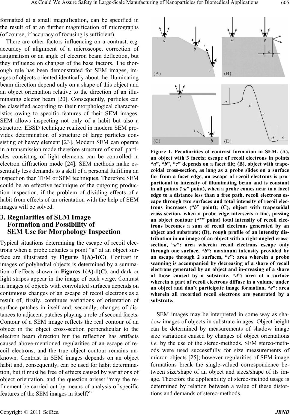 As Could We Assure Safety in Large-Scale Manufacturing of Nanoparticles for Biomedical Applications 605 formatted at a small magnification, can be specified in the result of at an further magnification of micrographs (of course, if accuracy of focusing is sufficient). There are other factors influencing on a contrast, e.g. accuracy of alignment of a microscope, correction of astigmatism or an angle of electron beam deflection, but they influence on changes of the base factors. The thor- ough rule has been demonstrated for SEM images, im- ages of objects oriented identically about the illuminating beam direction depend only on a shape of this object and an object orientation relative to the direction of an illu- minating elector beam [20]. Consequently, particles can be classified according to their morphological character- istics owing to specific features of their SEM images. SEM allows inspecting not only of a habit but also a structure. EBSD technique realized in modern SEM pro- vides determination of structure of large particles con- sisting of heavy element [23]. Modern SEM can operate in a transmission mode therefore structure of small parti- cles consisting of light elements can be controlled in electron diffraction mode [24]. SEM methods make es- sentially less demands to a skill of a personal fulfilling an inspection than TEM or SPM techniques. Therefore SEM could be an effective technique of the outgoing produc- tion inspection, if the problem of dividing effects of a habit from effects of an orientation with the help of SEM images will be solved. 3. Regularities of SEM Image Formation and Possibility of SEM Use for Morphology Inspection Typical situations determining the escape of recoil elec- trons when a probe actuates a point “a” at an object sur- face are illustrated by Figures 1(A)-1(C). Contrast in images of polyhedral objects is determined by a summa- tion of effects shown in Figures 1(A)-1(C), and dark or light stripes appear in the image of each verge. Contrast in images of objects with convoluted surfaces depends on continuous changes of an escape of recoil electrons as a result of, firstly, continues variations of orientation of surface patches in itself and, secondly, changes of dis- tances to adjacent patches playing a role of second facets. Contour of a SEM image reflects the real contour of an object in the object cross-section perpendicular to the electron beam direction but the reflection has artifacts caused above-mentioned regularities of an escape of re- coil electrons, and the true object contour remains un- known. Contrast in SEM images depends on an object habit and, consequently, can be used for habit determina- tion, but it must be free of effects caused by variations of object orientation, and the question arises: “may the re- finement be carried out by means of analysis of specific features of the SEM images in itself?” Figure 1. Peculiarities of contrast formation in SEM. (A), an object with 3 facets; escape of recoil electrons in points “a”, “b”, “c” depends on a facet tilt; (B), object with trape- zoidal cross-section, as long as a probe slides on a surface far from a facet edge, an escape of recoil electrons is pro- portional to intensity of illuminating beam and is constant in all points (“a” point), when a probe comes near to a facet edge to a distance less than a free path, recoil electrons es- cape through two surfaces and total intensity of recoil elec- trons increases (“b” point); (C), object with trapezoidal cross-section, when a probe edge intersects a line, passing an object contour (“*” point) total intensity of recoil elec- trons becomes a sum of recoil electrons generated by an object and substrate; (D), rough profile of an intensity dis- tribution in an image of an object with a right-angled cross- section, “a”: area wherein recoil electrons escape only through one surface, “b”: maximum intensity provided by an escape through 2 surfaces, “c”: area wherein a probe scanning is accompanied by decreasing of a share of recoil electrons generated by an object and in-creasing of a share of those caused by a substrate, “d”: area of a surface wherein a part of recoil electrons diffuse in a volume under an object and don’t participate image formation, “e”: area wherein all recorded recoil electrons are generated by a substrate. SEM images may be interpreted in some way as sha- dow images of objects in substrate images. Object height can be determined by measurements of shadow image size variations caused by changes of object orientations i.e. by the use of the stereo-methods. SEM stereo-meth- ods were used successfully for size measurements of micron objects [25]; however regularities of SEM image formations break the single-valued correspondence be- tween size/shape of an object and sizes/shape of its im- age. Therefore the applicability of stereo-method usage is determined by relation between a value of these distor- tions and demands of stereo-methods. Copyright © 2011 SciRes. JBNB  As Could We Assure Safety in Large-Scale Manufacturing of Nanoparticles for Biomedical Applications 606 Discrepancy between the real contour of an object and the contour of its image is associated with 2 factors: with a probe size and with a free path of recoil electrons. Res- olution attainable in present SEM equals to 1.0 nm. However focusing in SEM is determined on the basis of image sharpness and it is difficult to focus image with the absolute accuracy. Real size of a probe can is equal to 1.8 - 2.0 nm, and many images correspond to these val- ues. Minimal free path is observed for electrons with energy equal to 18 - 50 eV, and it is also equal to ≈ 1.0 nm. Therefore a minimal width of a stripe corresponding to an image of each edge equals to ≈ 3 nm, and it is un- likely that the real positions of spots of these edges can be found with accuracy better than ± 1.0 nm. However even an error ξ = ± 1.0 nm causes intolerable difficulties in habit determination. Firstly, even if an error of posi- tion determination of each point is ξ = ± 1.0 nm, an error in determination of a distance between two points is equal to 21. 5 nm, i.e., possible dispersion in possible sizes for objects with sizes ≤ 30 nm is ≥ 10%. Secondly, even if the point positions are found with the absolute precision the stereogram doesn’t give informa- tion concerning an object profile between these points. Theoretically, an object with rough sizes, found with the help of a stereogram, could be used as an initial pro- totype of an object’ for further refinement of its real sizes by means of the simulation that includes [20]: 1) Obtaining a SEM image of the prototype with a composition, corresponding to the object, under condi- tions identical to those used for the formation of with the help of software, e.g., Joy’s PC Monte Carlo Programs or SEMLP. 2) Fitting the model image to the experimental image by varying sizes and a habit of the prototype. 3) Accepting the habit and sizes of the prototype for which its image coincides with the actual image of the object as the true object habit and sizes. However when the dispersion of possible sizes is so large and even a rough object shape is unknown, a coin- cidence of a prototype intensity distribution and an ex- perimental intensity distribution of an object can be ob- tained under different ratios between sizes and shape of the prototype therefore similar way of the refinement of an object habit is impossible. SEM stereo-microscopy cannot be a mean of the habit control, at least, for objects with sizes ≤ 30 nm. It is nec- essary to find other ways to control an SEM image that allows obtaining information about a habit. SEM images can be controlled in principle with the help of following means: firstly, control of energy of electrons of an illu- minating beam influences on SEM images through changing distribution of centers of inelastic scattering, secondly, control of energy of recoil electrons influences on these images through variations of their free paths, thirdly, defocusing influences on these images through variations of probe sizes. Long-standing practice of SEM investigation didn’t expose dependences between changes of SEM images and variations of energy of electron of illuminating beams or recoil electrons that could be used for the habit determination. Therefore the hopes of pos- sibility of creation of SEM methods of habit inspection can be associated only with defocusings since it was al- ready shown that the superposition of intensity profiles corresponding to different focusings allows determining an object size at a half-height [26]. Paper [27] are de- voted to attempts to realize size and shape control with the help of series of defocusing images, but its approach has bad accuracy of measurements of an object height, it is not applicable to objects with sizes ≤ 50 nm. Routine related with the use of SPM, TEM and SEM eliminates possibilities of the creation of the outgoing inspections on their basis. However these microscopic methods have no alternatives for the inspection means in the nanoworld, since, firstly, only they provide obtaining information concerning structural-morphological pa- rameters of inspected objects and, secondly, only they possess space resolution necessary for measurements in the nanoworld. Therefore a situation with outgoing in- spection must be interpreted at the present as unsolved and this gap brings the threat to prospect of the nanopar- ticle technologies as a whole. Development of nanotech- nologies and overcoming of some already existing prob- lem (primarily in the pharmacology) demand new revo- lutionary in essence solutions. Possible solution of the problem of the habit particle determinations in condition of their mass production is suggested in [29] and it may be assumed as a basis in solution of the outgoing inspec- tion problem as a whole. 4. Methods of Habit Determination Founded on the Use of Convergence Beams Present SEM employs probes with a convergence angle χ ≈ 10–3 rad (for convenience a parallel beam), which im- plies that the depth of focus (DoF) is ≤ 0.5 µm [20]. If the DoF is greater than the object height, the size of the probe moving over the object surface remains unchanged. If a convergence angle increases, e.g. up to χ ≈ 10–1 rad (below: a convergence beam), the DoF drops to ≤10 nm and becomes smaller than the object height. The probe size varies during motion over the surface of an object even with a height of about 10 nm, and the probe exhibits defocusing. This defocusing (in contrast to the “instru- mental” defocusing that is caused by an inadequate exci- tation of the objective lens) may be called “habital.” The situation when the DoF is greater than the object height hereinafter is referred to as “sufficient depth of focus Copyright © 2011 SciRes. JBNB  As Could We Assure Safety in Large-Scale Manufacturing of Nanoparticles for Biomedical Applications 607 (SDoF)”, while the case when the DoF is smaller than the object height is called as “insufficient depth of focus (IDoF)”. The action of an object to the probe, which size varies during the motion over the object surface, can be characterized by “the action surface” or, in a certain sec- tion, by the “action curve”. In this study, the effect of habital defocusing is treated based on the notion of the action curve, but all laws remain also valid for the action surface, that is in application to 3D intensity distributions. The action curve IΣ is described by the expression [28]: 2 2 exp d π c c X xx J x (1) where 2 is the probe half-radius, which can be written in a linear approximation as 0 0 R zf f , (2) σ is the mean square deviation, xc is the coordinate of the probe center, J is the total probe intensity, z is the dis- tance from an output plane of the objective lens to a point on the object surface, f is the focal distance, σ0 is the ra- dius of the probe cross-section by the focal plane, R is the radius of the output aperture of the objective lens, |z – f| is the object height, and X is the integration domain determined by the object length in a given direction. Due to the dependence of δ on |z – f|, the action curve reflects the object shape. Since 2 , all routines developed for the modeling of SEM images (Joy’s PC Mote Carlo Programs, Casino Mote Carlo Program, etc.) are applica- ble to operations with the action curve. Use of IDoF images has a little interest by itself. Moreover the use of IDoF conditions for image forma- tion complicates an image interpretation since images of points, located at different distances from a focusing plane are formed under different conditions in focusing. But situation cardinally changes with a subtraction of a SDoF curve from an IDoF curve; a resulting curve re- flects distribution of the surface points with a height. Different curve is described by the expression [4,29, 30] 2 2 11 2 2 00 1exp π 1 expd c dif c c xx J I xx (3) where σ0 corresponds to SDoF conditions and σ1 does to IDoF those. On the strength of Exp. 3, Idif = 0 if σ1 = σ0. Let us introduce the notion of the zero object height plane (ZOHP) that is the plane relative to which the ob- ject height is measured. It is logical that ZOHP coincides with a substrate surface. It should be emphasized that at points, where the local actions of probes corresponding to different angles of convergence are equal, the yields of recoil electrons are also equal. Size of a probe for the parallel illuminating beam is constant along all the object and equal to a beam cross-section by the focusing plane. Size of a probe for a convergent illuminating beam is equal to a size of the probe of a parallel beam only in its focusing plane. Actions of the parallel and convergent beams on an object in points where the focusing plane of a convergent beam intersects an object surface are equal according to Exp. 3, therefore yields of recoil electrons generated both the beams are also equal (Figure 2(A)). If to superpose an intensity profile, corresponding to the parallel beam, over an intensity profile, conforming to the convergence beam and a focus on some cross-section of an object, then these profiles cross at a point where the focusing plane of the convergence beam intersects the intensity profile also of this beam (Figure 2(B)) [29]. If to subtract an intensity profile corresponding to the par- allel beam from a profile conforming to a convergent beam, the extrema and zeros of the differential curves observed in the vicinity of the same “crossing” point. Following the sequence of operations allows trans- forming an intensity distribution in an object image into its 3D image in the real space (in the object space) that reflects to true sizes and a habit of objects and corre- sponds to it in a maximally possible degree [4,29,30]: 1) To focus a convergent beam on ZOHP. 2) To move the focusing plane of the convergent beam over on a known distance Z and to settle a profile inten- sity conforming to the focusing on this object cross-sec- tion. 3) To superpose this profile over the profile corre- sponding to an object image in the parallel beam and to set the point of an intersection of the profiles; the inter- section point remotes from ZOHP for the Z distance. 4) To transform the intensity profile in to the 3D ob- ject image in the real space, these operations must be reiterated. Described approach ensures capabilities of habit re- constructions for objects with a height ≥ 10 - 15 nm, when SEM has the resolution 1.0 nm and a convergence angle ≈ 0.1 rad, Area of its applicability may be brought up to 5.0 - 7.0 nm by means of SEM with the resolution 0.4 - 0.5 nm or by means of increasing convergence an- gle. However it is possible to develop further the tech- niques founded on coprocessing of SEM images corre- sponding to probes with variable sizes. Firstly, coproc- essing of images corresponding to 2 beams with different convergences may be substituted by coprocessing of im- ages conforming to defocusings equal by absolute value Copyright © 2011 SciRes. JBNB  As Could We Assure Safety in Large-Scale Manufacturing of Nanoparticles for Biomedical Applications 608 Figure 2. Regularities of the method found focusings of a convergent beam on different object cross-sections. (A) 1, 1′ are generatrices of “a parallel beam”; 2, 2′, generatrices of “a convergence beam”; a is an object; b, a substrate; c1, a focusing plane of the parallel beam and initial focusing plane of the convergence beam; ci, an i-th focusing plane of the convergence beam; d1, a probe of the parallel beam and an initial probe of the convergence beam, both the probes correspond to focusings on the c1 plane; di, a probe of the convergence beam focused on the ci plane and simultane- ously a cross-section of the parallel beam by the ci plane, di ≡ d1; f, a point lying on a line inter-section the ci plane and the object surface; (B) Thin line is an intensity profile of an object images in a parallel beam; a thick line is an intensity profile of an image in a convergent beam corresponding to focusing on a z3 plane; zi, are virtual focusing planes, z3 is a real focusing plane corresponding to the ci plane of Figure 1(A); Z, a distance between the z3 plane and the substrate plane, that is also the plane of the initial focusing of the convergent beam and of the constant focusing of the paral- lel beam, h, an object height (the virtual focusing plane z6). and opposite by sign [30] (Figure 3(A)). When a probe is scanning over a surface of an object situated at the b plane from a bottom point to a top point, it moves from the focusing plane and the defocusing in- creases, but the defocusing value is changed to an oppo- site for an object situated in the c plane, since here a probe comes closer to the focusing plane, therefore in- fluence of habital defocusing is doubled in this method. Intersection of profiles, obtained in the method, occurs only at the planes of an object location (Figure 3(A)). The control of probe size in the method can be achieved by shifts of an object relative to these planes (Figure 3(B)). Therefore if to displace an object relative to both the planes by equal distances, the profiles corresponding to the different planes of an object location must be in- tersected at points where the location planes intersect the object surface. This rule may be used for transformation of the intensity profiles into 3D object images in the real space. Methods, founded on images conforming to defo- cusings equal by absolute value and opposite by sign, allow either to reduce doubly a convergence angle of a used beam without decreasing of method sensitivity or to increase its sensitivity without extension of a conver- gence angle. With decreasing the SEM resolution up to 0,4 nm, use of approach founded on images correspond- ing to different defocusings ensures in principle reducing the limiting size of inspected object up to 2.5 - 3.0 nm. Use of illuminating beams with different convergence allows employing alternative methods of direct recon- struction of an object habit, e.g. founded on reciprocal integral transformation of intensity profile on the basis of Exp. (3), but even the pursued methods give a sufficient idea about the essence of the approach and its opportuni- ties. It is necessary to point out the important peculiarity that attributes not only to the pursued methods but also to all possible SEM methods founded on the use of images arising in conditions of regular variations of probe sizes. Principles of these methods result from regularities of action curves, but only intensity profiles may be obtained in experiments, and although they reflect action curves, but are not similar to them. Therefore 3D images and habits obtained as the result of direct reconstruction re- flect a real object habit with errors. However 3D images or habits obtained by the direct reconstruction reflect the actual sizes and shapes of object with all its details and nuances, so it can be used as virtual prototypes of objects. Further refinement of object parameters can be carried out with the help of the familiar procedure involving re- ceipt of the prototype image in conditions corresponding to the obtaining conditions of the original object image and subsequent fitting of this prototype image to the ex- perimental object image by means of variations of proto- type shape and sizes. Different software products in- tended for the computation of virtual images (e.g. Joy’s PC Monte Carlo programs, Casino Monte Carlo Program, SEMLP, etc) can be used for this aim. Principle peculiar- ity of methods of a computer reconstruction of true sizes and a habit of an object that is suggested by the present paper is associated with the character of a prototype. Copyright © 2011 SciRes. JBNB 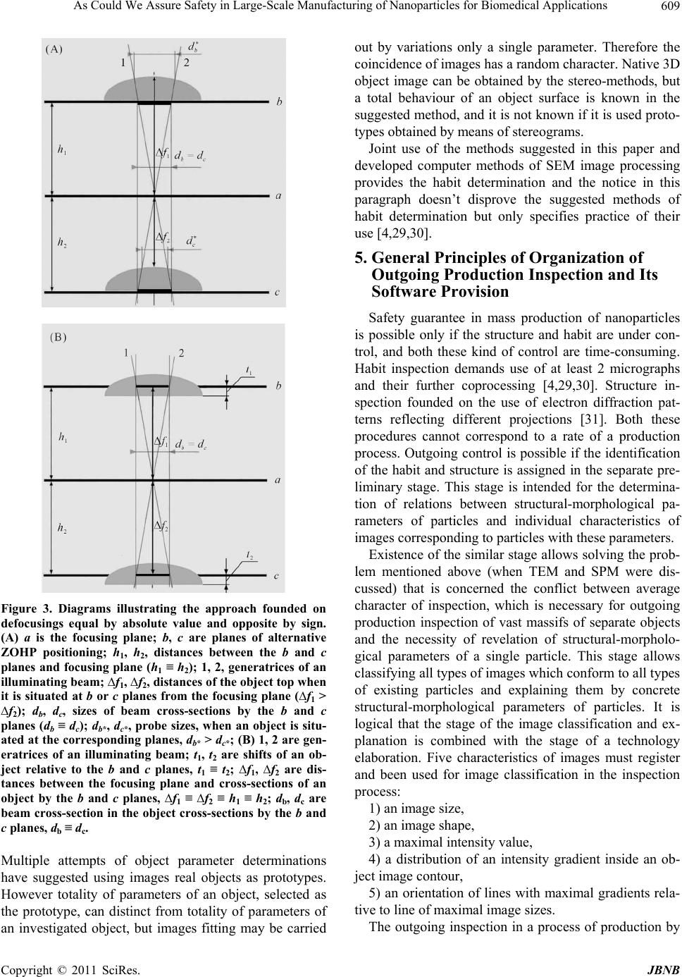 As Could We Assure Safety in Large-Scale Manufacturing of Nanoparticles for Biomedical Applications 609 Figure 3. Diagrams illustrating the approach founded on defocusings equal by absolute value and opposite by sign. (A) a is the focusing plane; b, c are planes of alternative ZOHP positioning; h1, h2, distances between the b and c planes and focusing plane (h1 ≡ h2); 1, 2, generatrices of an illuminating beam; ∆f1, ∆f2, distances of the object top when it is situated at b or c planes from the focusing plane (∆f1 > ∆f2); db, dc, sizes of beam cross-sections by the b and c planes (db ≡ dc); db*, dc*, probe sizes, when an object is situ- ated at the corresponding planes, db* > dc*; (B) 1, 2 are gen- eratrices of an illuminating beam; t1, t2 are shifts of an ob- ject relative to the b and c planes, t1 ≡ t2; ∆f1, ∆f2 are dis- tances between the focusing plane and cross-sections of an object by the b and c planes, ∆f1 ≡ ∆f2 ≡ h1 ≡ h2; db, dc are beam cross-section in the object cross-sections by the b and c planes, db ≡ dc. Multiple attempts of object parameter determinations have suggested using images real objects as prototypes. However totality of parameters of an object, selected as the prototype, can distinct from totality of parameters of an investigated object, but images fitting may be carried out by variations only a single parameter. Therefore the coincidence of images has a random character. Native 3D object image can be obtained by the stereo-methods, but a total behaviour of an object surface is known in the suggested method, and it is not known if it is used proto- types obtained by means of stereograms. Joint use of the methods suggested in this paper and developed computer methods of SEM image processing provides the habit determination and the notice in this paragraph doesn’t disprove the suggested methods of habit determination but only specifies practice of their use [4,29,30]. 5. General Principles of Organization of Outgoing Production Inspection and Its Software Provision Safety guarantee in mass production of nanoparticles is possible only if the structure and habit are under con- trol, and both these kind of control are time-consuming. Habit inspection demands use of at least 2 micrographs and their further coprocessing [4,29,30]. Structure in- spection founded on the use of electron diffraction pat- terns reflecting different projections [31]. Both these procedures cannot correspond to a rate of a production process. Outgoing control is possible if the identification of the habit and structure is assigned in the separate pre- liminary stage. This stage is intended for the determina- tion of relations between structural-morphological pa- rameters of particles and individual characteristics of images corresponding to particles with these parameters. Existence of the similar stage allows solving the prob- lem mentioned above (when TEM and SPM were dis- cussed) that is concerned the conflict between average character of inspection, which is necessary for outgoing production inspection of vast massifs of separate objects and the necessity of revelation of structural-morpholo- gical parameters of a single particle. This stage allows classifying all types of images which conform to all types of existing particles and explaining them by concrete structural-morphological parameters of particles. It is logical that the stage of the image classification and ex- planation is combined with the stage of a technology elaboration. Five characteristics of images must register and been used for image classification in the inspection process: 1) an image size, 2) an image shape, 3) a maximal intensity value, 4) a distribution of an intensity gradient inside an ob- ject image contour, 5) an orientation of lines with maximal gradients rela- tive to line of maximal image sizes. The outgoing inspection in a process of production by Copyright © 2011 SciRes. JBNB  As Could We Assure Safety in Large-Scale Manufacturing of Nanoparticles for Biomedical Applications 610 itself comes to the receipt of images and their classifica- tion in accordance with the found dependences between image characteristics and object parameters. Rate of im- age formation is determined by a scanning speed, a rate of image processing depends on computer productivity, and modern SEM and computer technologies ensure the conformity of the rate of the outgoing inspection to the rate of production processes. Reiterated operations of a determination of structure and morphology may be re- quired only in cases of unknown images disclosures. Single new image (or a few new images) may correspond to a particle with structural morphological parameters were accidentally missing during the preliminary stage, but a large share of unknown images corresponds, obvi- ously, to a fault of the technology. Reasons caused the rejection of SPM and TEM as the basis for technologies of outgoing inspections remain for their use as techniques of the uncovering of dependences between images of certain objects and their structural- morphological parameters in the preliminary stage. Be- sides the new major circumstance is appended to those already mentioned. SEM images are subjects of explana- tions therefore their explanation with SPM or TEM de- mands transfer of the object from one device into another and a comparison of images different in formation phys- ics and contrast. This circumstance confines once again possibilities of computerization of operations and in- creases the need in the visual inspection and in the level of operator skill that conflicts with the essence of the outgoing inspection of very vast massifs. Suggested me- thod is realized only by means of SEM that allows ful- filling all operations not only in the same device but with the same setting of an object into microscope and the identification of contrast nature as soon as an unusual image has been revealed. SEM techniques of a nature determination of images in the outgoing inspection are beyond the competition. Structural-morphological identification of object is founded on the 2 methods different in their physical foundations and in an instrumental support. However inspections of structure and morphology must be carried out jointly and the problem concerning matching these methods exists. Crystals with identical structure may have different faceting, but the crystal habits are associ- ated with structure more definitely especially for phases with different atomic structure [2,32,33]. Joint determi- nation of habit and structure allows revealing correlations between atomic structure and crystalline shapes; habit determination and, accordingly, analysis of image regu- larities is a reliable way in the outgoing production in- spection in these cases. Structure determines the catalytic activity for particles having no crystalline faceting espe- cially for amorphous objects. Identification of globular, ellipsoidal or more complicated unfaceted shapes on conditions, that their structure has been determined pre- liminary, are a way of their inspection. Habit control is a real way of the outgoing production inspection, although its trustworthiness depends on the accuracy of measure- ments. Realization of the outgoing inspection by means of exclusively SEM methods requires certain constructional peculiarities of microscope, 3 basic peculiarities are shown below. The structure inspection demands microscopes with attachments for formation of electron diffraction pat- tern in the transmission mode. This problem is solved very easily by way of the placement of a detection system with angle resolutions ≈ 10–3 rad. Similar sys- tem exists in TEM. Electrons with energies 30 - 50 keV allow obtaining diffraction patterns with satisfac- tory quality for particles with thickness up to 100 nm [34]. Increase of a convergence of illuminating beam en- larges dramatically blurring of a probe as the result of the spherical aberration. Possible limitations of the spherical aberration effect (including aberration asso- ciated with large angles of the beam convergence) have been solved in [35]. For the implementation of the method it is necessary to vary the convergence of the illuminating electron beam at precisely specified values. The problem of variation in the angles of con- vergence is solved by using a two-lens condenser and sets of condenser and objective diaphragms in [36]. The key problem of determination of the implementa- tion of the proposed approach is to bring the ZOHP into coincidence with the focusing plane. For nanodi- mensional objects, these planes must be brought into coincidence with angstrom accuracy [2,29,30]. The coincidence of the planes with this accuracy (espe- cially the planes with the a priori unknown relief) cannot be achieved in frameworks of routine SEM techniques (even with images arising in conditions of large convergences of illuminating beams). Therefore microscope must have the “stop limit” which breaks off the movement of a microscopic stage when the da- tum plane coincides with the focusing plane. Control- lers of the type used in SPM [19] provide solution of this problem. The preliminary stage of determination of depend- ences between structural-morphological parameters of particles and individual characteristics of images is not critical to slow down the rate of this determination, and SPM or TEM methods, at first glance, can be used in this stage for habit determinations. At that, TEM methods seem especially interested owing to the existence of overview images and the diffraction mode. However the Copyright © 2011 SciRes. JBNB  As Could We Assure Safety in Large-Scale Manufacturing of Nanoparticles for Biomedical Applications 611 SEM images are obligatory. 6. Conclusions Nanoparticles are promised for the use in many areas, but especially they are required in medicine and pharmacol- ogy. Information concerning solution of problems of medicine and pharmacology by means of nanotechnolo- gies appears regularly. Scientific and popular science literature is replete with papers describing new and new achievements, and, although attempts to take a sober view of the problem exist, majority of publications have panegyric hyperbolized character [7,9,10,37]. Problem of safety assurance is not examined. Of course, mentioned results and many, many other must be realized, but this realization will be criminal, if it will not be forestalled by development of the methods of adequate outgoing in- spection. Problems of structural-morphological parameters of nanoparticles are studied actively by methods of com- puter simulations: there are investigated dependences between these parameters and their sizes. These investi- gations are carried out in the equilibrium approximation [2], but situation is essentially complicated: since nano- technologies are based mainly on nonequilibrium proc- esses and structural-morphological parameters of parti- cles may be changed unpredictably. As a result, all at- tempts of fractional inspection as come to a size control. The time to recognize that only inspection of structural- morphological parameters of particles is the single way of the safety assurance has come. Nanoparticles recom- mended for medicine use usually have complicated shape: a solid inorganic kernel and an organic shell. However general properties of particle as a whole depend on structure and morphology of the kernel and only struc- tural-morphological inspection of the kernel ensures necessary properties of a complicates particles. There is another problem demands studying structural- morphological particles forming vast massifs. Nanoparti- cles arise not only in biomedical or pharmaceutical tech- nologies; they are produced, for example, as a result of different processes in many industrial technologies. In- dustrial particles provoke environmental pollution there- fore they are studied by ecologists and toxicologists. Physical and chemical properties of the medicinal and industrial nanoparticles are different, although these properties are substantially stimulated by surface effects. Joint investigations of industrial and biomedical particles are necessary for the solution of problems of pharmacol- ogy/medicine and environmental safety [16,17], but similar investigations are impossible without confronta- tion of structural-morphological parameters of both the particles types. Fractional inspection is also necessary for joint investigation. Method of habit determinations is the important con- stituent part of the outgoing inspection technique. How- ever there are other serious aftereffects associated with its creation. Creation of the feasible outgoing inspection method eliminates the barrier impeding acceptance of the adequate safety standard, taking into account the am- bivalence of nanoparticle technologies, and this standard can be accepted. Therefore this paper is the appeal to representatives of state and international structures, con- trolling approval of the adequate safety standard for the area of large-scale manufacturing of particles, with the call concerning necessity of acceleration works on the creation of an adequate safety standard. Only the ap- proval of similar standard assures safe development of nanotechnologies. All companies acting in an area of nanoparticle pro- duction are responsible for risks caused by nanoparticles for the life and the environment. However responsibility of pharmaceutical companies is utterly high, since an action area of their production is a human organism. Therefore this paper is the appeal to leaders of pharma- ceutical companies (primarily to global, such as Johnson & Johnson, RoShe, Novartis, Sanofi-Aventis, GlaxoS- mithKline, etc), the assurance of safety of patients, using your medicines, is your duty, and you must favor the development of the methods of outgoing inspections until a hardware realization will be created. Pharmaceutical companies already entered into the nanotechnology era, since nanoparticle technologies have moved from the category “promising” in to the category “developed”. Besides, adoption of methods of structural-morphologi- cal control allows to shorten a time necessary for testing of new medicines and to simplify its procedure. 7. Acknowledgements The authors would like to thank the staff of the Abdomi- nal Department of the Moscow P. A. Herzen Oncology Research Institute whose efforts have made possible the appearance of this publication. The authors are pleased to acknowledge their gratitude to A. Barnard, L. A. Curtiss and P. Zapol, D. J. Smith, S. J. Pennycook for information which has made it possible for them to pay attention to this problem. REFERENCES [1] S. Zuin, G. Pojana and A. Marcomini, “Effect-Oriented Physicochemical Characterization of Nanomaterials,” In: N. Montairo-Riviere and L. C. Tran, Eds., Nanotechnol- ogy. Characterization, Dosing and Health Effects, In- forma Healthcare USA, Inc, 2007, pp. 19-58. [2] A. S. Barnard, “Modelling of Nanoparticles: Approaches to Morphology and Evolution,” Reports on Progress in Physics, Vol. 73, No. 8, 2010, pp. 86502-86553. Copyright © 2011 SciRes. JBNB  As Could We Assure Safety in Large-Scale Manufacturing of Nanoparticles for Biomedical Applications 612 doi:10.1088/0034-4885/73/8/086502 [3] S. K. Maksimov and K. S. Maksimov, “Controlling the Surface Functionality of Nanomaterials,” Nanotechnolo- gies in Russia, Vol. 4, No. 3-4, 2009, pp. 188-200. doi:10.1134/S1995078009030070 [4] S. K. Maksimov and K. S. Maksimov, “Problem of Safety in Nanoparticle Mass Production and Its Solution by Means of Advanced Scanning Electron Microscopy,” Journal of Physics: Conference Series, Vol. 291, No. 1, 2011, Article ID 012014. doi:10.1088/1742-6596/291/1/012014. [5] W. C. W. Chan (Ed.), “Bio-Applications of Nanoparticles (Advances in Experimental Medicine and Biology),” Springer, Berlin, 2010. [6] M. Loizidou and A. M. Seifalian, “Nanotechnology and Its Applications in Surgery,” British Journal of Surgery, Vol. 97, 2010, pp. 463-465. doi:10.1002/bjs.7074 [7] A. S. Manmode, D. M. Sakarkar and N. M. Mahajan, “Nanoparticles-Tremendous Therapeutic Potential. A Re- view,” International Journal of PharmTech Research, Vol. 1, No. 4, 2009, pp. 1020-1027. [8] S. E. McNeil (Ed.), “Characterization of Nanoparticles Intended for Drug Delivery Series: Methods in Molecular Biology,” Vol. 697, Humana Press, Springer, Berlin, 2011. [9] Ya. M. Ram, H. K. S. Yadav, M. N. Singh and H. G. Shivakumar, “Nanoparticles, Promising Carriers in Drug Targeting: A Review,” Current Drug Therapy, Vol. 6, No. 2, 2011, pp. 87-96. doi:10.2174/157488511795304958 [10] R. Ravichandran, “Physico-Chemical Evaluation of Gymnemic Acids Nanocrystals,” International Journal of Nanoparticles, Vol. 3, 2010, pp. 280-296. doi:10.1504/IJNP.2010.035882 [11] K. Kazuo, “Nanomaterials May Call for a Reconsidera- tion of the Present Japanese Chemical Regulatory Sys- tem,” Clean Technologies and Environmental Policy, Vol. 8, No. 4, 2006, pp. 251-259. doi:10.1007/s10098-006-0060-9 [12] L. L. Ma, J. F. Zhao, J. Wang, J. Liu, Y. M. Duan, H. T. Liu, N. Li, J. Ruan, H. Wang and F. S. Hong, “The Acute Liver Injury in Mice Caused by Nano-Anatase TiO2,” Nanoscale Research Letters, No. 4, 2009, pp. 1275-1285. [13] C. M. Sayes and D. B. Warheit, “An in Vitro Investiga- tion of the Differential Cytotoxic Responses of Human and Rat Lung Epithelial Cell Lines Using TiO2 Nanopar- ticles,” International Journal of Nanotechnology, Vol. 5, No. 1, 2008, pp. 15-29. doi:10.1504/IJNT.2008.016548 [14] F. Yang, F. S. Hong, W. J. You, F. Gao, C. Wu and P. Yang, “Influences of Nano-Anatase TiO2 on the Nitrogen Metabolism of Growing Spinach,” Biological Trace Ele- ment Research, Vol. 110, No. 2, 2006, pp. 179-190. doi:10.1385/BTER:110:2:179 [15] I. Cavero, “Safety Pharmacology Society: 9th Annual Meeting,” Expert Opinion on Drug Safety, Vol. 9, No. 2, 2010, pp. 365-378. doi:10.1517/14740331003625577 [16] J. C. Marijnissen and L. Gradon (Eds.), “Nanoparticles in Medicine and Environment Inhalation and Health Ef- fects,” Springer, Berlin, 2010. [17] K. Donaldson. “Resolving the Nanoparticles Paradox,” Nanomedicine, Vol. 1, No. 2, 2006, pp. 229-234. doi:10.2217/17435889.1.2.229 [18] J. Hutchison, A. Kirkland (Eds.), “Nanocharacterization,” RSC Publishing, London, 2007. [19] B. Bhushan and O. Marti, “Scanning Probe Microscopy —Principle of Operation. Instrumentation and Probes,” In: B. Bhushan, Ed., Springer Handbook of Nanotech- nology, 2nd Edition, Springer, Berlin, pp. 239-278. [20] D. E. Newbury, D. C. Joy, P. Echin, C. E. Fiory and J. I. Goldstein, “Advanced Scanning Electron Microscopy and X-Ray Microanalysis,” Plenum Press, New York, 2003. [21] S. K. Maksimov and K. S. Maksimov, “Concept of Safety Standard and Outgoing Inspection in Technologies of Nanoparticles,” Nanotechnics, No 18. 2009, pp. 5-12 (in Russian). [22] R. Vidya, “Minimum Variance and VOQL Chain Sam- pling Plans-ChSP-4(c1, c2),” Communications in Statis- tics: Simulation and Computation, Vol. 37, No. 7, 2008, pp. 1466-1478. doi:10.1080/03610910601096585 [23] D. J. Dingley and M. M. Nowell, “The Use of Electron Backscatter Diffraction for the Investigation of Nano Crystalline Materials and the Move towards Orientation Imaging in the TEM,” Microchimica Acta, Vol. 147, No. 3, 2004, pp. 157-165. doi:10.1007/s00604-004-0186-6 [24] M. J. Carr, C. E. Lyman and J. M. Cowley, “Identifica- tion of Unknowns in Electron Diffraction,” In: J. M. Cowley, Ed., Electron Diffraction Technique, Vol. 1, Oxford University Press, Oxford, 992, pp. 212-216. [25] B. Minnich, H. Leeb, E. W. N. Bernroider and A. Lamer- schwandtner, “Three-Dimensional Morphometry in Scan- ning Electron Microscopy: A Technique for Accurate Dimensional And Angular Measurements of Microstruc- tures Using Stereopaired Digitized Images and Digital Image Analysis,” Journal of Microscopy, Vol. 195, No. 1, 1999, pp. 23-33. doi:10.1046/j.1365-2818.1999.00478.x [26] M. I. Ilyin, A. I. Kozlitin, S. K. Maksimov, A. V. Nikitin, and V. V. Bannikov, “High Accuracy and Precision Measurements of Line Dimensions of Sub-0.25-Micron and Nanometer Objects in Scanning Electron Micros- copy,” Scanning, Vol. 19, 1997, pp. 224-225. [27] A. Zlotnik, Sh. Ben-Yaish and Z. Zalevski, “Extending of the Depth of Focus for Enhanced Three-Dimensional Image and Profilometry: An Overview,” Applied Optics, Vol. 48, No. 34, 2009, pp. H105-H112. doi:10.1364/AO.48.00H105 [28] K. S. Maksimov, “Systematic Features of Defocused Images in Scanning Electron Microscopy and Nanoscale size Measurements,” Semiconductors, Vol. 43, No. 13, 2009, pp. 1725-1727. doi:10.1134/S1063782609130235 [29] S. K. Maksimov and K.S. Maksimov, “New Approach in Metrology for Nanotechnologies,” Technical Physics Let- ters, Vol. 35, No. 10, 2010, pp. 938-941. doi:10.1134/S1063785010100196 Copyright © 2011 SciRes. JBNB  As Could We Assure Safety in Large-Scale Manufacturing of Nanoparticles for Biomedical Applications Copyright © 2011 SciRes. JBNB 613 [30] S. K. Maksimov and K. S. Maksimov, “Control over the Morphology of Nanoobjects and a New Way to Accom- plish It,” Bulletin of the Russian Academy of Sciences. Physics, Vol. 75, No. 9, Allerton Press, Inc, 2011, pp. 1171-1175. [31] B. K. Vainstein, B. B. Zvyagin and A. S. Avilov, “Elec- tron Diffraction Structure Analysis,” In: M. J. Cowley, Ed., Electron Diffraction Technique, Vol. 2, Oxford Uni- versity Press, Oxford, 1992. [32] A. S. Barnard, R. R. Yeredla and H. Xu, “Modelling the Effect of Particle Shape on the Phase Stability of ZrO2 Nanoparticles,” Nanotechnology, Vol. 17, No. 6, 2006, pp. 3039-3047. doi:10.1088/0957-4484/17/12/038 [33] G. Guisbiers, G. Abudukelimu, F. Clement and M. Wau- telet, “Effects of Shape on the Phase Stability of Nanopar- ticles,” Journal of Computational and Theoretical Nano- science, Vol. 4, No. 2, 2007, pp. 309-315. [34] Z. G. Pinsker, “Electron Diffraction,” Butterworth, Lon- don, 1949. [35] T. Kawasaki, Y. Yoshida, H. Ose and H. Todokoro, “Electron Beam Apparatus with Aberration Corrector,” US Patent 7199365, 2007. [36] H. Kitsuki, K. Aoki and M. Sato, “Scanning Electron Microscope,” US Patent 7442929, 2008. [37] J. V. Lauritsen, Ja. Kibsgaard, S. Helveg, H. Topsoe, B. S. Clausen, E. Lægsgaard and F. Besenbacher, “Size-De- pendent Structure of MoS2 Nanocrystals,” Nature Nano- technology, Vol. 2, No. 1, 2007, pp. 53-58. doi:10.1038/nnano.2006.171
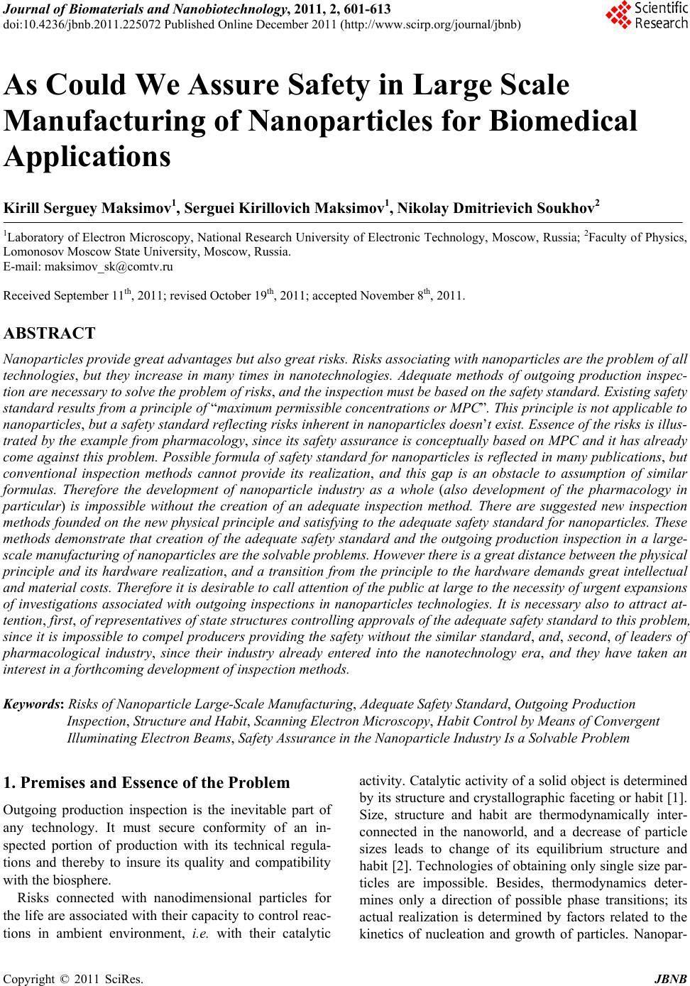
|