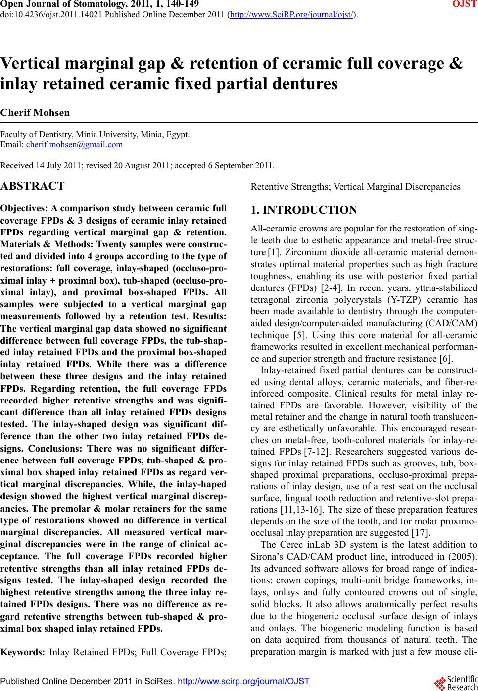
 Open Journal of Stomatology, 2011, 1, 140-149 doi:10.4236/ojst.2011.14021 Published Online December 2011 (http://www.SciRP.org/journal/ojst/ OJST ). Published Online December 2011 in SciRes. http://www.scirp.org/journal/OJST Vertical marginal gap & retention of ceramic full coverage & inlay retained ceramic fixed partial dentures Cherif Mohsen Faculty of Dentistry, Minia University, Minia, Egypt. Email: cherif.mohsen@gmail.com Received 14 July 2011; revised 20 August 2011; accepted 6 September 2011. ABSTRACT Objectives: A comparison study between ceramic full coverage FPDs & 3 designs of ceramic inlay retained FPDs regarding vertical marginal gap & retention. Materials & Methods: Twenty samples were construc- ted and divided into 4 groups according to the type of restorations: full coverage, inlay-shaped (occluso-pro- ximal inlay + proximal box), tub-shaped (occluso-pro- ximal inlay), and proximal box-shaped FPDs. All samples were subjected to a vertical marginal gap measurements followed by a retention test. Results: The vertical marginal gap data showed no significant difference between full coverage FPDs, the tub-shap- ed inlay retained FPDs and the proximal box-shaped inlay retained FPDs. While there was a difference between these three designs and the inlay retained FPDs. Regarding retention, the full coverage FPDs recorded higher retentive strengths and was signifi- cant difference than all inlay retained FPDs designs tested. The inlay-shaped design was significant dif- ference than the other two inlay retained FPDs de- signs. Conclusions: There was no significant differ- ence between full coverage FPDs, tub-shaped & pro- ximal box shaped inlay retained FPDs as regard ver- tical marginal discrepancies. While, the inlay-haped design showed the highest vertical marginal discrep- ancies. The premolar & molar retainers for the same type of restorations showed no difference in vertical marginal discrepancies. All measured vertical mar- ginal discrepancies were in the range of clinical ac- ceptance. The full coverage FPDs recorded higher retentive strengths than all inlay retained FPDs de- signs tested. The inlay-shaped design recorded the highest retentive strengths among the three inlay re- tained FPDs designs. There was no difference as re- gard retentive strengths between tub-shaped & pro- ximal box shaped inlay retained FPDs. Keywords: Inlay Retained FPDs; Full Coverage FPDs; Retentive Strengths; Vertical Marginal Discrepancies 1. INTRODUCTION All-ceramic crowns are popular for the restoration of sing- le teeth due to esthetic appearance and metal-free struc- ture [1]. Zirconium dioxide all-ceramic material demon- strates optimal material properties such as high fracture toughness, enabling its use with posterior fixed partial dentures (FPDs) [2-4]. In recent years, yttria-stabilized tetragonal zirconia polycrystals (Y-TZP) ceramic has been made available to dentistry through the computer- aided design/computer-aided manufacturing (CAD/CAM) technique [5]. Using this core material for all-ceramic frameworks resulted in excellent mechanical performan- ce and superior strength and fracture resistance [6]. Inlay-retained fixed partial dentures can be construct- ed using dental alloys, ceramic materials, and fiber-re- inforced composite. Clinical results for metal inlay re- tained FPDs are favorable. However, visibility of the metal retainer and the change in natural tooth translucen- cy are esthetically unfavorable. This encouraged resear- ches on metal-free, tooth-colored materials for inlay-re- tained FPDs [7-12]. Researchers suggested various de- signs for inlay retained FPDs such as grooves, tub, box- shaped proximal preparations, occluso-proximal prepa- rations of inlay design, use of a rest seat on the occlusal surface, lingual tooth reduction and retentive-slot prepa- rations [11,13-16]. The size of these preparation features depends on the size of the tooth, and for molar proximo- occlusal inlay preparation are suggested [17]. The Cerec inLab 3D system is the latest addition to Sirona’s CAD/CAM product line, introduced in (2005). Its advanced software allows for broad range of indica- tions: crown copings, multi-unit bridge frameworks, in- lays, onlays and fully contoured crowns out of single, solid blocks. It also allows anatomically perfect results due to the biogeneric occlusal surface design of inlays and onlays. The biogeneric modeling function is based on data acquired from thousands of natural teeth. The preparation margin is marked with just a few mouse cli- 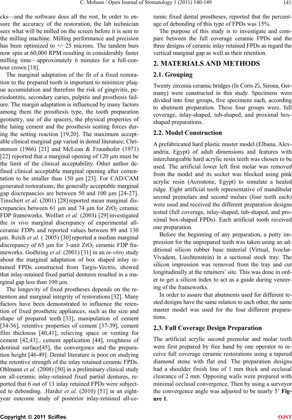 C. Mohsen / Open Journal of Stomatology 1 (2011) 140-149 141 cks—and the software does all the rest. In order to en- sure the accuracy of the restoration, the lab technician sees what will be milled on the screen before it is sent to the milling machine. Milling performance and precision has been optimized to +/−25 microns. The tandem burs now spin at 60,000 RPM resulting in considerably faster milling time—approximately 6 minutes for a full-con- tour crown [18]. The marginal adaptation of the fit of a fixed restora- tion to the prepared tooth is important to minimize plaq- ue accumulation and therefore the risk of gingivitis, pe- riodontitis, secondary caries, pulpitis and prosthesis fail- ure. The margin adaptation is influenced by many factors among them the prosthesis type, the tooth preparation geometry, use of die spacers, the physical properties of the luting cement and the prosthesis seating forces dur- ing the setting reaction [19,20]. The maximum accept- able clinical marginal gap varied in dental literature; Chri- stensen (1966) [21] and McLean & Fraunhofer (1971) [22] reported that a marginal opening of 120 μm must be the limit of the clinical acceptability. Other author de- fined clinical acceptable marginal opening after cemen- tation to be smaller than 150 μm [23]. For CAD/CAM generated restorations, the generally acceptable marginal gap discrepancies are between 50 and 100 μm [24-27]. Tinschert et al. (2001) [28] reported mean marginal dis- crepancies between 61 μm and 74 μm for ZrO2 ceramic FDP frameworks. Wolfart et al. (2003) [29] investigated the in vivo marginal discrepancy of experimental all- ceramic FDPs and reported values between 89 and 130 μm. Reich et al. ( 2005) [30] reported a median marginal discrepancy of 65 μm for 3-unit ZrO2 ceramic FDP fra- meworks. Goëhring et al. (2001) [31] in an in-vitro study about the marginal adaptation of box shaped inlay re- tained FPDs constructed from Targis-Vectris, showed that inlay-retained fixed partial dentures resulted in a ma- rginal gap less than 100 μm. The longevity of fixed prostheses depends on the re- tention and marginal integrity of restorations [32]. Many factors have been demonstrated to influence the reten- tion of fixed prosthetic appliances, such as the size and shape of prepared teeth [33], manipulation of cement [34-36], retentive properties of cement [37-39], cement film thickness [40,41], relieving space or venting for cement [42,43] , cement application [44], roughness of dentinal surface[45], the convergence and the prepara- tion height [46-49]. Dental literature is poor on studying the retentive strength of the inlay retained ceramic FPDs. Ohlmann et al. (2008) [50] in a preliminary clinical study on all-ceramic inlay-retained fixed partial dentures, re- ported that 6 out of 13 inlay retained FPDs were subject- ed to debonding. .Harder et al. (2010) [51] in an eight- year outcome study of posterior inlay-retained all-ce- ramic fixed dental prostheses, reported that the percent- age of debonding of this type of FPDs was 15%. The purpose of this study is to investigate and com- pare between the full coverage ceramic FPDs and the three designs of ceramic inlay retained FPDs as regard the vertical marginal gap as well as their retention. 2. MATERIALS AND METHODS 2.1. Grouping Twenty zirconia ceramic bridges (In Coris Zi, Sirona, Ger- many) were constructed in this study. Specimens were divided into four groups, five specimens each, according to abutment preparation. These four groups were, full coverage, inlay-shaped, tub-shaped, and proximal box- shaped preparations. 2.2. Model Construction A prefabricated hard plastic master model (Elbana, Alex- andria, Egypt) of adult dimensions and features with interchangeable hard acrylic resin teeth was chosen to be used. The artificial lower left first molar was removed from the model and its socket was blocked using pink acrylic resin (Acrostone, Egypt) to simulate a healed ridge. Eight artificial teeth representative of mandibular second premolars and second molars (four teeth each) were used and received the different preparation designs tested (full coverage, inlay-shaped, tub-shaped, and pro- ximal box-shaped FPDs). Each artificial tooth received one preparation. Before the beginning of any preparation, a putty im- pression for the unprepared teeth was taken using an ad- ditional silicon rubber base material (Virtual, Ivoclar- Vivadent, Liechtenstein) in a sectional stock tray. The silicon impression was removed from the tray and cut longitudinally at the retainers’ site. This was done in ord- er to get a silicon index to act as a guide during veneer- ing of the frameworks. In order to assure that abutments used for different te- sted designs have the same relation to each other, the same master model was used for the four different prepara- tions. 2.3. Full Coverage Design Preparation The artificial acrylic second premolar and molar teeth were first prepared by free hand by one operator to re- ceive full coverage ceramic restorations using a tapered diamond stone with flat end. The preparation designs had a shoulder finish line of 1 mm thick and occlusal clearance of 2 mm. Opposing walls were prepared with minimal occlusal convergence. Then by using a surveyor the convergence angle was adjusted to be nearly 5˚ Fig- ure 1. C opyright © 2011 SciRes. OJST 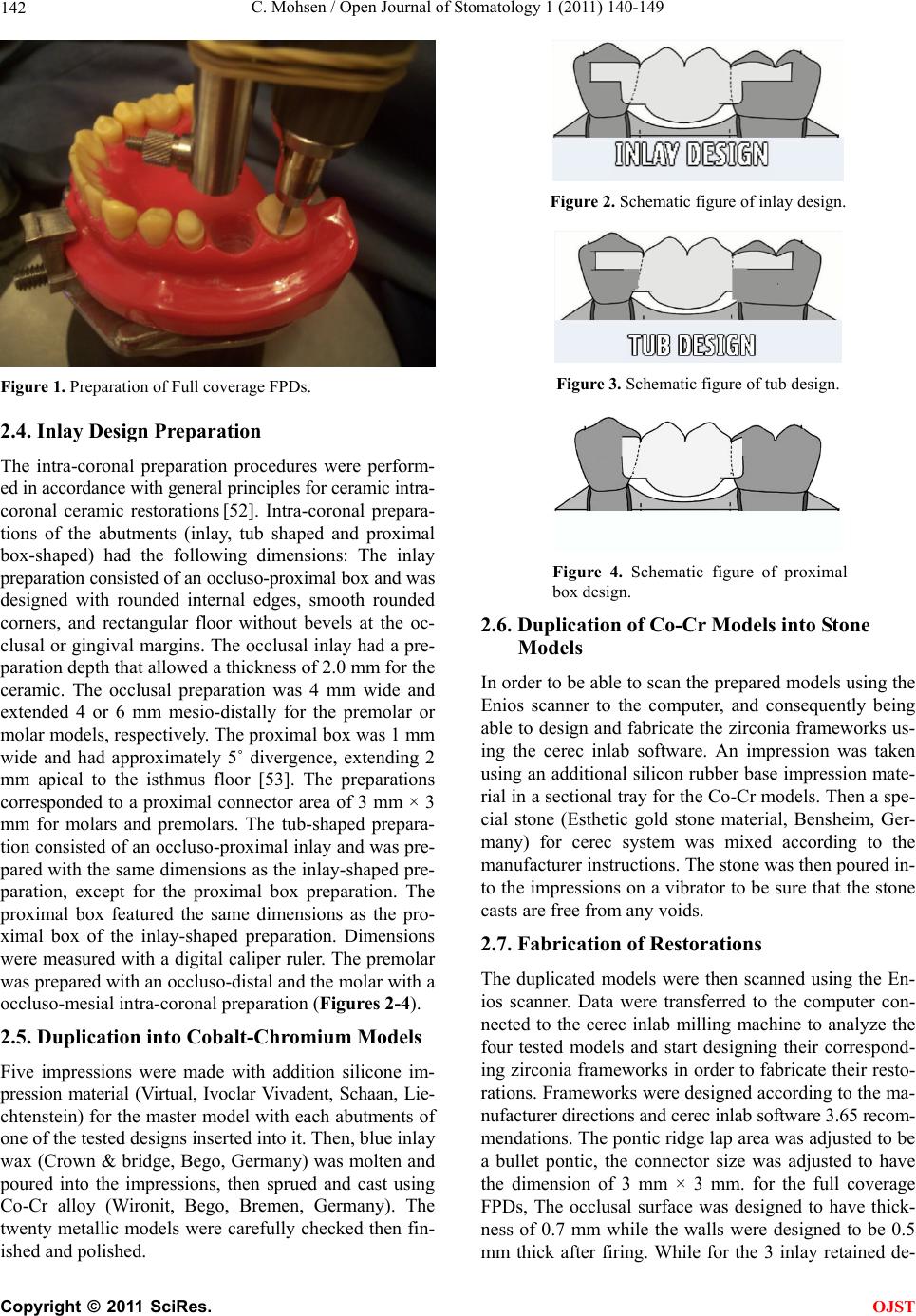 C. Mohsen / Open Journal of Stomatology 1 (2011) 140-149 142 Figure 1. Preparation of Full coverage FPDs. 2.4. Inlay Design Preparation The intra-coronal preparation procedures were perform- ed in accordance with general principles for ceramic intra- coronal ceramic restorations [52]. Intra-coronal prepara- tions of the abutments (inlay, tub shaped and proximal box-shaped) had the following dimensions: The inlay preparation consisted of an occluso-proximal box and was designed with rounded internal edges, smooth rounded corners, and rectangular floor without bevels at the oc- clusal or gingival margins. The occlusal inlay had a pre- paration depth that allowed a thickness of 2.0 mm for the ceramic. The occlusal preparation was 4 mm wide and extended 4 or 6 mm mesio-distally for the premolar or molar models, respectively. The proximal box was 1 mm wide and had approximately 5˚ divergence, extending 2 mm apical to the isthmus floor [53]. The preparations corresponded to a proximal connector area of 3 mm × 3 mm for molars and premolars. The tub-shaped prepara- tion consisted of an occluso-proximal inlay and was pre- pared with the same dimensions as the inlay-shaped pre- paration, except for the proximal box preparation. The proximal box featured the same dimensions as the pro- ximal box of the inlay-shaped preparation. Dimensions were measured with a digital caliper ruler. The premolar was prepared with an occluso-distal and the molar with a occluso-mesial intra-coronal preparation (Figures 2-4). 2.5. Duplication into Cobalt-Chromium Models Five impressions were made with addition silicone im- pression material (Virtual, Ivoclar Vivadent, Schaan, Lie- chtenstein) for the master model with each abutments of one of the tested designs inserted into it. Then, blue inlay wax (Crown & bridge, Bego, Germany) was molten and poured into the impressions, then sprued and cast using Co-Cr alloy (Wironit, Bego, Bremen, Germany). The twenty metallic models were carefully checked then fin- ished and polished. Figure 2. Schematic figure of inlay design. Figure 3. Schematic figure of tub design. Figure 4. Schematic figure of proximal box design. 2.6. Duplication of Co-Cr Models into Stone Models In order to be able to scan the prepared models using the Enios scanner to the computer, and consequently being able to design and fabricate the zirconia frameworks us- ing the cerec inlab software. An impression was taken using an additional silicon rubber base impression mate- rial in a sectional tray for the Co-Cr models. Then a spe- cial stone (Esthetic gold stone material, Bensheim, Ger- many) for cerec system was mixed according to the manufacturer instructions. The stone was then poured in- to the impressions on a vibrator to be sure that the stone casts are free from any voids. 2.7. Fabrication of Restorations The duplicated models were then scanned using the En- ios scanner. Data were transferred to the computer con- nected to the cerec inlab milling machine to analyze the four tested models and start designing their correspond- ing zirconia frameworks in order to fabricate their resto- rations. Frameworks were designed according to the ma- nufacturer directions and cerec inlab software 3.65 recom- mendations. The pontic ridge lap area was adjusted to be a bullet pontic, the connector size was adjusted to have the dimension of 3 mm × 3 mm. for the full coverage FPDs, The occlusal surface was designed to have thick- ness of 0.7 mm while the walls were designed to be 0.5 mm thick after firing. While for the 3 inlay retained de- C opyright © 2011 SciRes. OJST 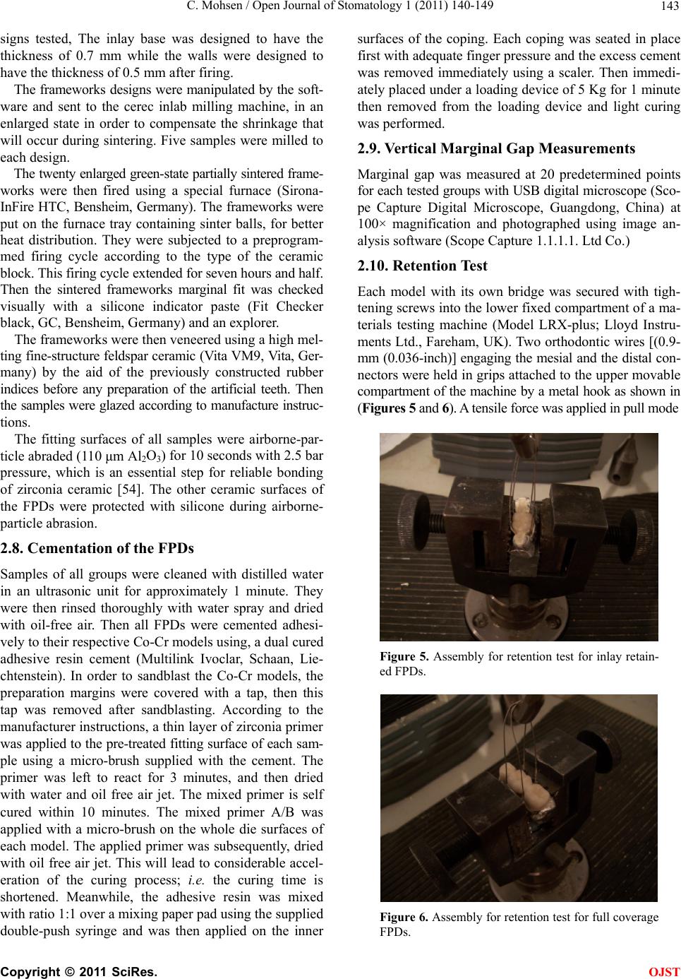 C. Mohsen / Open Journal of Stomatology 1 (2011) 140-149 143 signs tested, The inlay base was designed to have the thickness of 0.7 mm while the walls were designed to have the thickness of 0.5 mm after firing. The frameworks designs were manipulated by the soft- ware and sent to the cerec inlab milling machine, in an enlarged state in order to compensate the shrinkage that will occur during sintering. Five samples were milled to each design. The twenty enlarged green-state partially sintered frame- works were then fired using a special furnace (Sirona- InFire HTC, Bensheim, Germany). The frameworks were put on the furnace tray containing sinter balls, for better heat distribution. They were subjected to a preprogram- med firing cycle according to the type of the ceramic block. This firing cycle extended for seven hours and half. Then the sintered frameworks marginal fit was checked visually with a silicone indicator paste (Fit Checker black, GC, Bensheim, Germany) and an explorer. The frameworks were then veneered using a high mel- ting fine-structure feldspar ceramic (Vita VM9, Vita, Ger- many) by the aid of the previously constructed rubber indices before any preparation of the artificial teeth. Then the samples were glazed according to manufacture instruc- tions. The fitting surfaces of all samples were airborne-par- ticle abraded (110 μm Al2O3) for 10 seconds with 2.5 bar pressure, which is an essential step for reliable bonding of zirconia ceramic [54]. The other ceramic surfaces of the FPDs were protected with silicone during airborne- particle abrasion. 2.8. Cementation of the FPDs Samples of all groups were cleaned with distilled water in an ultrasonic unit for approximately 1 minute. They were then rinsed thoroughly with water spray and dried with oil-free air. Then all FPDs were cemented adhesi- vely to their respective Co-Cr models using, a dual cured adhesive resin cement (Multilink Ivoclar, Schaan, Lie- chtenstein). In order to sandblast the Co-Cr models, the preparation margins were covered with a tap, then this tap was removed after sandblasting. According to the manufacturer instructions, a thin layer of zirconia primer was applied to the pre-treated fitting surface of each sam- ple using a micro-brush supplied with the cement. The primer was left to react for 3 minutes, and then dried with water and oil free air jet. The mixed primer is self cured within 10 minutes. The mixed primer A/B was applied with a micro-brush on the whole die surfaces of each model. The applied primer was subsequently, dried with oil free air jet. This will lead to considerable accel- eration of the curing process; i.e. the curing time is shortened. Meanwhile, the adhesive resin was mixed with ratio 1:1 over a mixing paper pad using the supplied double-push syringe and was then applied on the inner surfaces of the coping. Each coping was seated in place first with adequate finger pressure and the excess cement was removed immediately using a scaler. Then immedi- ately placed under a loading device of 5 Kg for 1 minute then removed from the loading device and light curing was performed. 2.9. Vertical Marginal Gap Measurements Marginal gap was measured at 20 predetermined points for each tested groups with USB digital microscope (Sco- pe Capture Digital Microscope, Guangdong, China) at 100× magnification and photographed using image an- alysis software (Scope Capture 1.1.1.1. Ltd Co.) 2.10. Retention Test Each model with its own bridge was secured with tigh- tening screws into the lower fixed compartment of a ma- terials testing machine (Model LRX-plus; Lloyd Instru- ments Ltd., Fareham, UK). Two orthodontic wires [(0.9- mm (0.036-inch)] engaging the mesial and the distal con- nectors were held in grips attached to the upper movable compartment of the machine by a metal hook as shown in (Figur es 5 and 6). A tensile force was applied in pull mode Figure 5. Assembly for retention test for inlay retain- ed FPDs. Figure 6. Assembly for retention test for full coverage FPDs. C opyright © 2011 SciRes. OJST 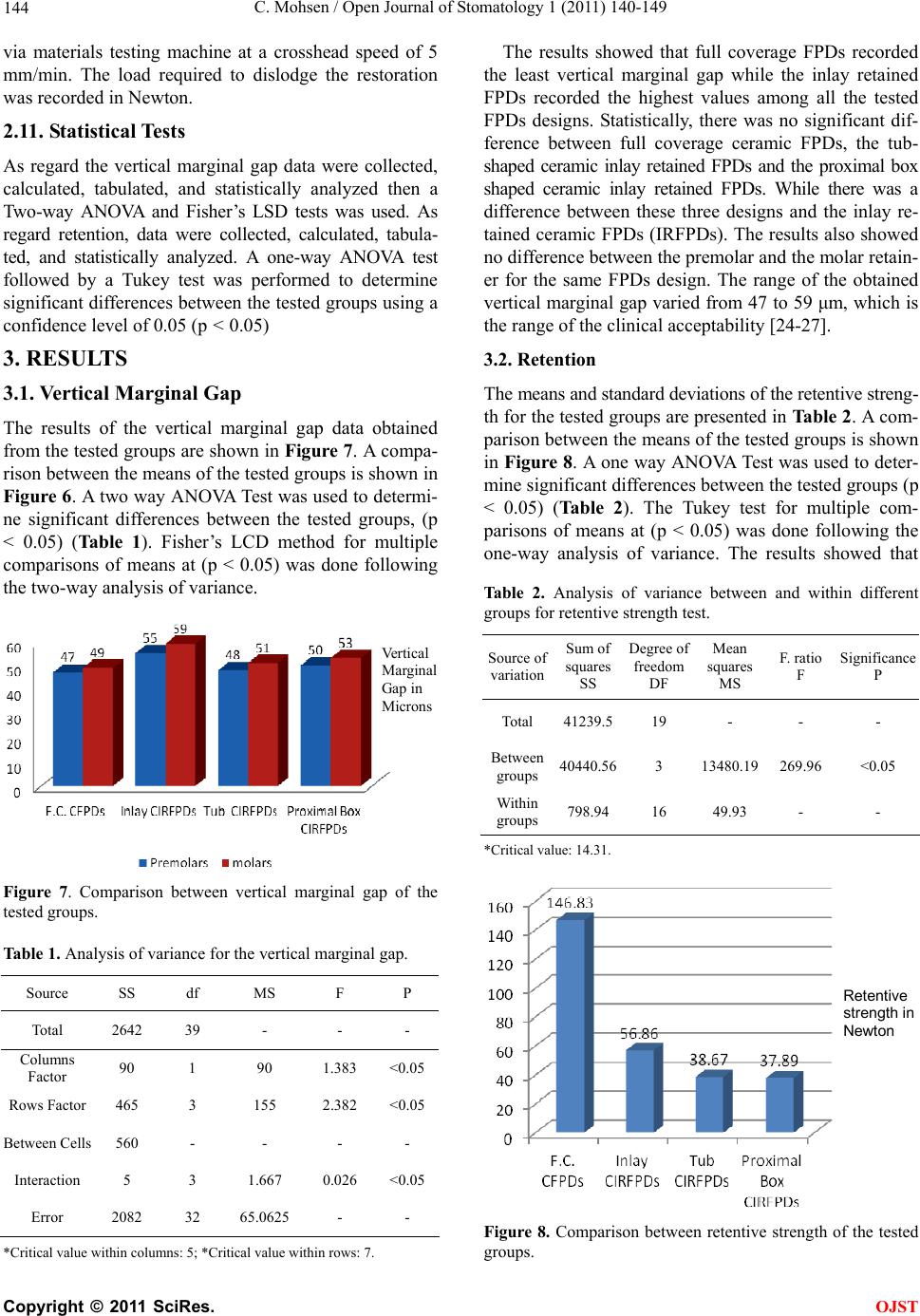 C. Mohsen / Open Journal of Stomatology 1 (2011) 140-149 144 via materials testing machine at a crosshead speed of 5 mm/min. The load required to dislodge the restoration was recorded in Newton. 2.11. Statistical Tests As regard the vertical marginal gap data were collected, calculated, tabulated, and statistically analyzed then a Two-way ANOVA and Fisher’s LSD tests was used. As regard retention, data were collected, calculated, tabula- ted, and statistically analyzed. A one-way ANOVA test followed by a Tukey test was performed to determine significant differences between the tested groups using a confidence level of 0.05 (p < 0.05) 3. RESULTS 3.1. Vertical Marginal Gap The results of the vertical marginal gap data obtained from the tested groups are shown in Figure 7. A compa- rison between the means of the tested groups is shown in Figure 6. A two way ANOVA Test was used to determi- ne significant differences between the tested groups, (p < 0.05) (Table 1). Fisher’s LCD method for multiple comparisons of means at (p < 0.05) was done following the two-way analysis of variance. Vertical Margina Gap in Microns Figure 7. Comparison between vertical marginal gap of the tested groups. Table 1. Analysis of variance for the vertical marginal gap. Source SS df MS F P Total 2642 39 - - - Columns Factor 90 1 90 1.383 <0.05 Rows Factor 465 3 155 2.382 <0.05 Between Cells 560 - - - - Interaction 5 3 1.667 0.026 <0.05 Error 2082 32 65.0625 - - *Critical value within columns: 5; *Critical value within rows: 7. The results showed that full coverage FPDs recorded the least vertical marginal gap while the inlay retained FPDs recorded the highest values among all the tested FPDs designs. Statistically, there was no significant dif- ference between full coverage ceramic FPDs, the tub- shaped ceramic inlay retained FPDs and the proximal box shaped ceramic inlay retained FPDs. While there was a difference between these three designs and the inlay re- tained ceramic FPDs (IRFPDs). The results also showed no difference between the premolar and the molar retain- er for the same FPDs design. The range of the obtained vertical marginal gap varied from 47 to 59 μm, which is the range of the clinical acceptability [24-27]. 3.2. Retenti on The means and standard deviations of the retentive streng- th for the tested groups are presented in Table 2. A com- parison between the means of the tested groups is shown in Figure 8. A one way ANOVA Test was used to deter- mine significant differences between the tested groups (p < 0.05) (Table 2). The Tukey test for multiple com- parisons of means at (p < 0.05) was done following the one-way analysis of variance. The results showed that Table 2. Analysis of variance between and within different groups for retentive strength test. Source of variation Sum of squares SS Degree of freedom DF Mean squares MS F. ratio F Significance P Total 41239.519 - - - Between groups 40440.563 13480.19 269.96 <0.05 Within groups 798.9416 49.93 - - *Critical value: 14.31. Retentive strength in Newton Figure 8. Comparison between retentive strength of the tested groups. C opyright © 2011 SciRes. OJST 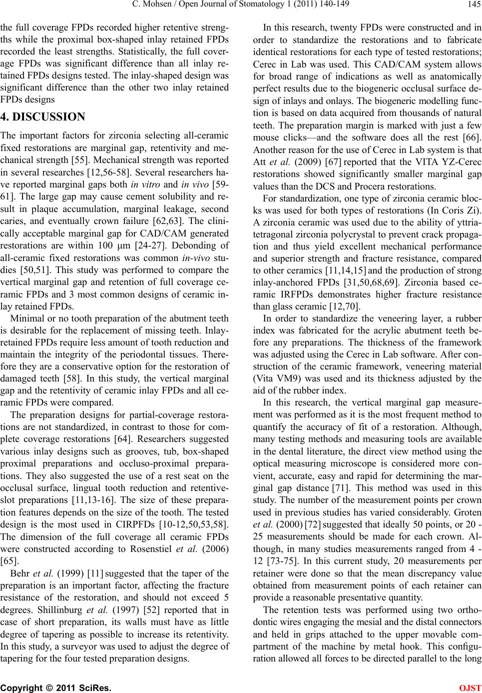 C. Mohsen / Open Journal of Stomatology 1 (2011) 140-149 145 the full coverage FPDs recorded higher retentive streng- ths while the proximal box-shaped inlay retained FPDs recorded the least strengths. Statistically, the full cover- age FPDs was significant difference than all inlay re- tained FPDs designs tested. The inlay-shaped design was significant difference than the other two inlay retained FPDs designs 4. DISCUSSION The important factors for zirconia selecting all-ceramic fixed restorations are marginal gap, retentivity and me- chanical strength [55]. Mechanical strength was reported in several researches [12,56-58]. Several researchers ha- ve reported marginal gaps both in vitro and in vivo [59- 61]. The large gap may cause cement solubility and re- sult in plaque accumulation, marginal leakage, second caries, and eventually crown failure [62,63]. The clini- cally acceptable marginal gap for CAD/CAM generated restorations are within 100 μm [24-27]. Debonding of all-ceramic fixed restorations was common in-vivo stu- dies [50,51]. This study was performed to compare the vertical marginal gap and retention of full coverage ce- ramic FPDs and 3 most common designs of ceramic in- lay retained FPDs. Minimal or no tooth preparation of the abutment teeth is desirable for the replacement of missing teeth. Inlay- retained FPDs require less amount of tooth reduction and maintain the integrity of the periodontal tissues. There- fore they are a conservative option for the restoration of damaged teeth [58]. In this study, the vertical marginal gap and the retentivity of ceramic inlay FPDs and all ce- ramic FPDs were compared. The preparation designs for partial-coverage restora- tions are not standardized, in contrast to those for com- plete coverage restorations [64]. Researchers suggested various inlay designs such as grooves, tub, box-shaped proximal preparations and occluso-proximal prepara- tions. They also suggested the use of a rest seat on the occlusal surface, lingual tooth reduction and retentive- slot preparations [11,13-16]. The size of these prepara- tion features depends on the size of the tooth. The tested design is the most used in CIRPFDs [10-12,50,53,58]. The dimension of the full coverage all ceramic FPDs were constructed according to Rosenstiel et al. (2006) [65]. Behr et al. (1999) [11] suggested that the taper of the preparation is an important factor, affecting the fracture resistance of the restoration, and should not exceed 5 degrees. Shillinburg et al. (1997) [52] reported that in case of short preparation, its walls must have as little degree of tapering as possible to increase its retentivity. In this study, a surveyor was used to adjust the degree of tapering for the four tested preparation designs. In this research, twenty FPDs were constructed and in order to standardize the restorations and to fabricate identical restorations for each type of tested restorations; Cerec in Lab was used. This CAD/CAM system allows for broad range of indications as well as anatomically perfect results due to the biogeneric occlusal surface de- sign of inlays and onlays. The biogeneric modelling func- tion is based on data acquired from thousands of natural teeth. The preparation margin is marked with just a few mouse clicks—and the software does all the rest [66]. Another reason for the use of Cerec in Lab system is that Att et al. (2009) [67] reported that the VITA YZ-Cerec restorations showed significantly smaller marginal gap values than the DCS and Procera restorations. For standardization, one type of zirconia ceramic bloc- ks was used for both types of restorations (In Coris Zi). A zirconia ceramic was used due to the ability of yttria- tetragonal zirconia polycrystal to prevent crack propaga- tion and thus yield excellent mechanical performance and superior strength and fracture resistance, compared to other ceramics [11,14,15] and the production of strong inlay-anchored FPDs [31,50,68,69]. Zirconia based ce- ramic IRFPDs demonstrates higher fracture resistance than glass ceramic [12,70]. In order to standardize the veneering layer, a rubber index was fabricated for the acrylic abutment teeth be- fore any preparations. The thickness of the framework was adjusted using the Cerec in Lab software. After con- struction of the ceramic framework, veneering material (Vita VM9) was used and its thickness adjusted by the aid of the rubber index. In this research, the vertical marginal gap measure- ment was performed as it is the most frequent method to quantify the accuracy of fit of a restoration. Although, many testing methods and measuring tools are available in the dental literature, the direct view method using the optical measuring microscope is considered more con- vient, accurate, easy and rapid for determining the mar- ginal gap distance [71]. This method was used in this study. The number of the measurement points per crown used in previous studies has varied considerably. Groten et al. (2000) [72] suggested that ideally 50 points, or 20 - 25 measurements should be made for each crown. Al- though, in many studies measurements ranged from 4 - 12 [73-75]. In this current study, 20 measurements per retainer were done so that the mean discrepancy value obtained from measurement points of each retainer can provide a reasonable presentative quantity. The retention tests was performed using two ortho- dontic wires engaging the mesial and the distal connectors and held in grips attached to the upper movable com- partment of the machine by metal hook. This configu- ration allowed all forces to be directed parallel to the long C opyright © 2011 SciRes. OJST  C. Mohsen / Open Journal of Stomatology 1 (2011) 140-149 146 axis of the retainers during testing. As regard the results of the vertical marginal gap measurements, there was no significant difference be- tween full coverage FPDs, tub-shaped & proximal box shaped inlay retained FPDs as regard vertical marginal discrepancies. This may be due to the fact that the full coverage FPDs has a longer perimeter but different mar- ginal configurations than these 2 designs of inlay re- tained FPDs, these 3 designs were measured at 20 pre- determined points each, this means that the distance be- tween each pre-determined point for the full coverage FPDs was much a part than that of the 2 designs of inlay retained FPDs. Chan et al. (1989) [76] reported that the marginal discrepancy of each restoration may vary great- ly at different location. The number of pre-determined points for measuring the vertical marginal gap should be promotional to the perimeter of the finish line, so that the distance between each 2 pre-determined points be equal. At the same time, the results showed a difference in vertical marginal gap between the full coverage FPDs and the inlay-shaped design, this may be due to the dif- ference in the preparation geometry, marginal configure- tions [55] and the location and orientation of tubules [77] between these 2 designs. Also, the results showed a sig- nificant difference between tub-shaped & proximal box shaped inlay retained FPDs from one side and the inlay-shaped FPDs from the other side, this may be attri- buted to the fact that the latter design possess a much longer perimeter and has the geometry of the former 2 designs together. The results also showed that the premolar & molar re- tainers for the same type of restorations showed no dif- ference in vertical marginal discrepancies. These results were in agreement with Ebeid (2006) [78]. This may be attributed to the small difference between premolar and molar regarding dimensions. The obtained vertical marginal gap data in the present study ranged from 47 to 59 μm are within the clinical acceptable values, since the criteria of 100 μm was con- sidered by some authors as the maximum clinical ac- ceptable marginal gap [24-27]. As regard the forces needed to dislodge the all cera- mic as well as the inlay retained FPDs, the results show- ed that, a significant difference was found between the tested FPDs. The all ceramic FPDs recorded the highest forces to be dislodged and were significant difference than all inlay retained FPDs designs tested. The inlay- shaped design was significant difference than the other two inlay retained FPDs designs. These results could not be compared with results of other researchers as this study is the pioneer in studying in-vitro the retentivity of inlays retained FPDs. In two clinical evaluations, Edel- hoff et al. (2001) [13] and Edelhoff & Sorensen (2002) [79], they reported that compared to crown retained FPDs, de-bonding of inlay retained FPDs appear to be much too high. These difference in retention between the two tested FPDs may be attributed to the fact that longer preparations (full coverage FPDs) have more surface area and therefore are more retentive than the shorter preparations (inlay retained FPDs) [52] . Another reason for these difference may be due to the conclusion of Er- nst et al. (2005) [80] who reported that the frictional re- sistance between a prepared tooth and ceramic crown is as important as the adhesive bond strength. 5. CONCLUSIONS 1) There was no significant difference between full coverage FPDs, tub-shaped & proximal box shaped IRFPDs as regard vertical marginal discrepancies. 2) The inlay-shaped design showed the highest ver- tical marginal discrepancies. 3) The premolar & molar retainers for the same type of restorations showed no difference in vertical marginal discrepancies. 4) All measured vertical marginal discrepancies were in the range of clinical acceptance. 5) The full coverage FPDs recorded higher reten- tive strengths than all inlay retained FPDs designs tested. 6) The inlay-shaped design recorded the highest retentive strengths among the three inlay retained FPDs designs. 7) There was no difference as regard retentive str- engths between tub-shaped & proximal box shaped IRFPDs. REFERENCES [1] Blatz, M.B., Sadan, A. and Kern, M. (2003) Resin-ce- ramic bonding: A review of the literature. Journal of Prosthetic Dentistry, 89, 268-274. doi:10.1067/mpr.2003.50 [2] Fischer, H., Weber, M. and Marx, R. (2003) Lifetime prediction of all-ceramic bridges by computational methods. Journal of Dental Research, 82, 238-242. doi:10.1177/154405910308200317 [3] Luthardt, R.G., Holzhuter, M., Sandkuhl, O., Herold, V., Schnapp, J.D., Kuhlisch, E., et al. (2002) Reliability and properties of ground Y-TZP-zirconia ceramics. Journal of Dental Research, 81, 487-491. doi:10.1177/154405910208100711 [4] Suttor, D., Bunke, K., Hoescheler, S., Hauptmann, H. and Hertlein, G. (2001) LAVA—The system for all-ceramic ZrO2 crown and bridge frameworks. International Jour- nal of Computerized Dentistry, 4, 195-206. [5] Sjolin, R., Sundh, A. and Bergman, M. (1999) The Decim system for the production of dental restorations. International Journal of Computerized Dentistry, 2, 197- 207. C opyright © 2011 SciRes. OJST  C. Mohsen / Open Journal of Stomatology 1 (2011) 140-149 147 [6] Christel, P., Meunier, A., Heller, M., Torre, J.P. and Peille, C.N. (1989) Mechanical properties and short-term in-vivo evaluation of yttrium-oxide-partially-stabilized zirconia. Journal of Biomedical Materials Research, 23, 45-61. doi:10.1002/jbm.820230105 [7] Stokholm, R. and Isidor, F. (1996) Resin-bonded inlay retainer prostheses for posterior teeth. A 5-year clinical study. International Journal of Prosthodontics, 9, 161- 166. [8] Zaghloul, H.H., Younis, J.F. and Morsi, T.S. (2008) The influence of preparation design and connector thickness on fracture resistance of fiber-reinforced composite ad- hesive fixed partial dentures. Egyptian Dental Journal, 54, 1037-1047. [9] Ozcan, M., Breuklander, M.H. and Vallitu, P.K. (2005) The effect of box preparation on the strength of glass fi- ber-reinforced composite inlay-retained fixed partial dentures. Journal of Prosthetic Dentistry, 93, 337-345. doi:10.1016/j.prosdent.2005.01.006 [10] Xie, Q., Lassila, L.V.P. and Vallittu, P.K. (2007) Com- parison of load-bearing capacity of direct resinbonded fiber-reinforced composite FPDs with four framework designs. Journal of Dentistry, 35, 578-582. doi:10.1016/j.jdent.2007.04.003 [11] Behr, M., Rosentritt, A., Leibrock, S. and Schneider- Feyrer, G.H. (1999) In-vitro study of fracture strength and marginal adaption of fibre-reinforced adhesive fixed partial inlay dentures. Journal of Dentistry, 27, 163-168. doi:10.1016/S0300-5712(98)00036-0 [12] Wolfart, S., Ludwigb, K., Uphausc, A. and Kerna, M. (2007) Fracture strength of all-ceramic posterior inlay- retained fixed partial dentures. Dental Materials, 23, 1513-1520. doi:10.1016/j.dental.2006.12.006 [13] Edelhoff, D., Spiekermann, H. and Yildirim, M. (2001) Metal-free inlay-retained fixed partial dentures. Quintes- sence International, 32, 269-281. [14] Chow, T.W., Chung, R.W., Chu, F.C. and Newsome, P.R. (2002) Tooth preparations designed for posterior resin- bonded fixed partial dentures: A clinical report. Journal of Prosthetic Dentistry, 88, 561-564. doi:10.1067/mpr.2002.129374 [15] El-Mowafy, O.M. (1998) Posterior resin-bonded fixed partial denture with a modified retentive design: A clini- cal report. Journal of Prosthetic Dentistry, 80, 9-11. doi:10.1016/S0022-3913(98)70084-8 [16] El-Mowafy, O.M. and Rubo, M.H. (2000) Retention of a posterior resin-bonded fixed partial denture with a modi- fied design: An in vitro study. International Journal of Prosthodontics, 13, 425-431. [17] Bishop, K., Priestley, D., Deans, R. and Joshi, R. (1997) The use of adhesive metal-ceramic restorations as an al- ternative to conventional crown and bridge materials. British Dental Journal, 182, 101-106. doi:10.1038/sj.bdj.4809315 [18] Hondrum, S.O. (1992) A review of the strength proper- ties of dental ceramic. British Dental Journal, 67, 859- 865. [19] Belser, U.C., Macente, M.I. and Richter, W.A. (1985) Fit of three porcelain-fused-to-metal marginal designs in vivo: A SEM study. Journal of Prosthetic Dentistry, 53, 24-29. doi:10.1016/0022-3913(85)90058-7 [20] Jacob, M.S. and Windler, A.S. (1991) An investigation of dental luting cements solubility as a function of the mar- ginal gap. Journal of Prosthetic Dentistry, 65, 436-442. doi:10.1016/0022-3913(91)90239-S [21] Christensen, G.J. (1966) Marginal fit of gold inlay cast- ings. Journal of Prosthetic Dentistry, 16, 297-305. [22] McLean, J.W. and Fraunhofer, J.A. (1971) The estima- tion of cement film by an in vitro technique. British Dental Journal, 131, 107. [23] Rosentritt, M., Behr, M. and Handel, G. (2001) In vitro study of fracture strength and marginal adaptation of fi- ber-reinforced composite versus all ceramic fixed partial dentures. Dental M a terials, 8, 51. [24] Andersson, M., Carlsson, L., Persson, M. and Bergman, B. (1996) Accuracy of machine milling and spark erosion with a CAD/CAM system. Journal of Prosthetic Den- tistry, 76, 187-193. [25] Persson, M., Andersson, M. and Bergman, B. (1995) The accuracy of a high-precision digitizer for CAD/CAM of crowns. Journal of Prosthetic Dentistry, 74, 223-229. [26] Bindl, A. and Mörmann, W.H. (2007) Fit of all-ceramic posterior fixed partial denture frameworks in vitro. In- ternational Journal of Periodontics & Restorative Den- tistry, 27, 567-575. [27] Witkowski, S., Komine, F. and Gerds, T. (2006) Marginal accuracy of titanium copings fabricated by casting and CAD/CAM techniques. Journal of Prosthetic Dentistry, 96, 47-52. [28] Tinschert, J., Natt, G., Mautsch, W., Spiekermann, H. and Anusavice, K.J. (2001) Marginal fit of alumina- and zir- conia-based fixed partial dentures produced by a CAD/ CAM system. Open Dentistry, 26, 367-374. [29] Wolfart, S., Wegner, S.M., Al-Halabi, A. and Kern, M. (2003) Clinical evaluation of marginal fit of a new ex- perimental all-ceramic system before and after cementa- tion. International Journal of Prosthodontics, 16, 587- 592. [30] Reich, S., Wichmann, M., Nkenke, E. and Proeschel, P. (2005) Clinical fit of all-ceramic three-unit fixed partial dentures, generated with three different CAD/CAM sys- tems. European Journal of Oral Sciences, 113, 174-179. [31] Göehring, T.N., Peters, O.A. and Lutz, F. (2001) Mar- ginal adaptation of inlay-retained adhesive fixed partial dentures after mechanical and thermal stress: An in vitro study. Journal of Prosthetic Dentistry, 86, 81-92. [32] Tjan, A.H., Dunn, J.R. and Grant, B.E. (1992) Marginal leakage of cast gold crowns luted with an adhesive resin cement. Journal of Prosthetic Dentistry, 67, 11-15. [33] Smith, B.G. (1970) The effect of the surface roughness of prepared dentin on the retention of castings. Journal of Prosthetic Dentistry, 23, 187-197. [34] Bruce, W.L. and Stevens, L. (1989) Strength properties of three zinc phosphate cements mixed to two different consistencies. Australian Dental Journal, 34, 132-135. [35] Zaki, A.F., Karl, F. and Leinfelder, K.F. (1992) Rapid mixing of zinc phosphate cement for fixed prosthodontic procedures. Journal of Prosthetic Dentistry, 67, 120-125. [36] Pearson, G.J. and Atkinson, A.S. (1987) Effects of tem- perature change on the working and setting characteris- tics of water-based dental cements. Dental Materials, 3, 275-279. [37] White, S.N., Sorensen, J.A., Kang, S.K. and Caputo, A.A. (1992) Microleakage of new crown and fixed partial den- C opyright © 2011 SciRes. OJST  C. Mohsen / Open Journal of Stomatology 1 (2011) 140-149 148 ture luting agents. Journal of Prosthetic Dentistry, 67, 156-161. [38] Phillips, R.W. (1989) Skinner’s science of dental material. 9th Edition, W. B. Saunders, Philadelphia, 479-501. [39] White, S.N. and Kipnis, V. (1993) Effect of adhesive luting agents on the marginal seating of cast restoration. Journal of Prosthetic Dentistry, 69, 28-31. [40] White, S.N. and Yu, Z. (1992) Film thickness of new adhesive luting agents. Journal of Prosthetic Dentistry, 67, 782-785. [41] White, S.N. and Yu, Z. (1992) The effect of the adhesive luting agent-dentinal surface interactions on film thick- ness. Journal of Prosthetic Dentistry, 68, 49-52. doi:10.1016/0022-3913(92)90283-G [42] White, S.N., Yu, Z. and Kipnis, V. (1992) The effect of seating force on film thickness of new adhesive luting agents. Journal of Prosthetic Dentistry, 68, 484-489. doi:10.1016/0022-3913(92)90414-6 [43] Passon, C., Lambert, R.H., Lambert, R.L. and Newman, S. (1992) The effect of multiple layers of die-spacer on crown retention. Open Dentistry, 17, 42-49. [44] Assif, D., Rimer, Y. and Aviv, I. (1987) The flow of zinc phosphate cement under a fullcoverage restoration and its effect on marginal adaptation according to the location of cement application. Quintessence International, 18, 765- 774. [45] Ayad, M.F., Rosenstiel, S.F. and Salama, M. (1997) In- fluence of tooth surface roughness and type of cement on retention of complete cast crown. Journal of Prosthetic Dentistry, 77, 116-121. doi:10.1016/S0022-3913(97)70223-3 [46] El-Mowafy, O.M., Fenton, A.H., Forrester, N. and Milen- kovic, M. (1996) Retention of metal ceramic crowns ce- mented with resin cements: Effects of preparation taper and height. Journal of Prosthetic Dentistry, 76, 524-529. doi:10.1016/S0022-3913(96)90012-8 [47] Bresciano, M., Schierano, G., Manzella, C., Screti, A., Bignardi, C. and Preti, G. (2005) Retention of luting agents on implant abutments of different height and taper. Clinical Oral Implants Research, 16, 594-598. doi:10.1111/j.1600-0501.2005.01159.x [48] Bernal, G., Okamura, M. and Munoz, C.A. (2003) The effects of abutment taper, length and cement type on re- sistance to dislodgement of cement-retained, implant supported restorations. Journal of Prosthodontics, 12, 111-115. doi:10.1016/S1059-941X(03)00006-8 [49] Lawson, N.C., Burgess, B.O. and Mercante, D. (2007) Crown retention and flexural strength of eight provi- sional cements. Journal of Prosthetic Dentistry, 98, 455- 460. doi:10.1016/S0022-3913(07)60145-0 [50] Ohlmann, B., Rammelsberg, P., Schmitter, M., Schwarz, S. and Gabbert, O. (2008) All-ceramic inlay-retained fixed partial dentures: Preliminary results from a clinical study. Journal of Dentistry, 36, 692-696. doi:10.1016/j.jdent.2008.04.017 [51] Harder, S., Wolfart, S., Echbach, S. and Kern, M. (2010) Eight-year outcome of posterior inlay-retained all-cera- mic fixed dental prostheses. Journal of Dentistry, 38, 875-881. doi:10.1016/j.jdent.2010.07.012 [52] Shillingburg, H.T., Hobo, S. and Whitsett, L. (1997) Fundamentals of fixed prosthodontics. 3rd Edition, Quin- tessence, Chicago, 119-137, 171-174. [53] Song, H.Y., Yi, Y.J., Cho, L.R. and Park, D.Y. (2003) Effects of two preparation designs and pontic distance on bending and fracture strength of fiber-reinforced com- posite inlay fixed partial dentures. Journal of Prosthetic Dentistry, 90, 347-353. doi:10.1016/S0022-3913(03)00434-7 [54] Calamia, J.R. (1989) High-strength porcelain bonded restorations: Anterior and posterior. Quintessence Inter- national, 20, 717-726. [55] Kokubo, Y., Tsumita, M., Kano, T., Sakurai, S. and Fi- kushima, S. (2011) Clinical marginal and internal gaps of zirconia all-ceramic crowns. Journal of Prosthodontic Research, 55, 40-43. doi:10.1016/j.jpor.2010.09.001 [56] Mohsen, S.A. (2010) Fracture resistance of three ceramic inlay retained fixed partial denture designs. An in-vitro comparative study. Journal of Prothodontics, 19, 531- 535. doi:10.1111/j.1532-849X.2010.00621.x [57] Mohsen, S.A. (2010) Effect of preparation design & con- nector size on the fracture resistance of metal ceramic and all ceramic inlay retained fixed partial denture. Egyptian Dental Journal, 56, 699-709. [58] Kiliçarslan, M.A., Kedici, P.S., Küçükesşmen, H.C. and Uludağ, B.C. (2004) In vitro fracture resistance of poste- rior metal-ceramic and all-ceramic inlay-retained resin- bonded fixed partial dentures. Journal of Prosthetic Den- tistry, 92, 365-370. doi:10.1016/j.prosdent.2004.07.001 [59] Kokubo, Y., Ohkubo, C., Tsumita, M., Miyashita, A., Vult von Steyern, P. and Fukushima, S. (2005) Clinical marginal and internal gaps of Procera AllCeram crowns. Journal of Oral Rehabilitation, 32, 526-530. doi:10.1111/j.1365-2842.2005.01458.x [60] Boening, K.W., Wolf, B.H., Schmidt, A.E., Kästner, K. and Walter, M.H. (2000) Clinical fit of procera all ceram crowns. Journal of Prosthetic Dentistry, 84, 419-424. doi:10.1067/mpr.2000.109125 [61] May, K.B., Russell, M.M., Razzoog, M.E. and Lang, B.R. (1998) Precision of fit: The procera all ceram crown. Journal of Prosthetic Dentistry, 80, 394-404. doi:10.1016/S0022-3913(98)70002-2 [62] Felton, D.A., Kanoy, B.E., Bayne, S.C. and Wirthman, G.P. (1991) Effect of in vivo crown margin discrepancies on periodontal health. Journal of Prosthetic Dentistry, 65, 357-364. doi:10.1016/0022-3913(91)90225-L [63] Knoernschild, K.L. and Campbell, S.D. (2000) Perio- dontal tissue responses after insertion of artificial crowns and fixed partial dentures. Journal of Prosthetic Den- tistry, 84, 492-498. doi:10.1067/mpr.2000.110262 [64] Cronin, R.J. and Cagna, D.R. (1997) An update on fixed prosthodontics. Journal of the American Dental Associa- tion, 128, 425-436. [65] Rosenstiel, S.F., Land, M.F. and Fujimoto, J. (2006) Con- temporary fixed prosthodontics. 4th Edition, Mosby, St. Louis, 323-327. [66] Sirona Dental Systems (2011) The in Lab System and its component parts. Your stepping stones to success. [67] Att, W., Komine, F., Gerds, T. and Strub, J.R. (2009) Marginal adaptation of three different zirconium dioxide three-unit fixed dental prostheses. Journal of Prosthetic Dentistry, 101, 239-247. doi:10.1016/S0022-3913(09)60047-0 [68] Pospiech, P., Rammelsberg, P., Goldhofer, G., et al. (1996) All-ceramic resin bonded bridges. A 3-dimensional fi- C opyright © 2011 SciRes. OJST  C. Mohsen / Open Journal of Stomatology 1 (2011) 140-149 Copyright © 2011 SciRes. 149 OJST nite-element analysis study. European Journal of Oral Sciences, 104, 390-395. doi:10.1111/j.1600-0722.1996.tb00097.x [69] Kern, M. and Strub, J.R. (1998) Bonding to alumina ceramic in restorative dentistry: Clinical results over up to 5 years. Journal of Dentistry, 26, 245-249. doi:10.1016/S0300-5712(97)00009-2 [70] Magne, P., Perakis, N., Belser, U.C. and Krejci, I. (2002) Stress distribution of inlay anchored adhesive fixed par- tial dentures: A finite element analysis of theinfluence of restorative materials and abutment preparation design. Journal of Prosthetic Dentistry, 87, 516-527. doi:10.1067/mpr.2002.124367 [71] Sorensen, J.A. (1990) A standardized method for deter- mination of crown margin fidelity. Journal of Prosthetic Dentistry, 64, 18-24. doi:10.1016/0022-3913(90)90147-5 [72] Groten, M., Axmann, D., Probster, L. and Weber, H. (2000) Determination of the minimum number of mar- ginal gap measurements required for pratical in-vitro testing. Journal of Prosthetic Dentistry, 83, 40-49. doi:10.1016/S0022-3913(00)70087-4 [73] Rinke, S., Hüls, A. and Jahn, L. (1995) Marginal accu- racy and fracture strength of conventional and copy- milled all-ceramic crowns. Inter natio nal Journal of Pro s- thodontics, 8, 303-310. [74] Sulaiman, F., Chai, J., Jameson, L. and Wozniak, W.A. (1997) Comparison of the marginal fit of In-Ceram, IPS Empress and Procera. International Journal of Prostho- dontics, 10, 478-484. [75] Mohsen, S.A. and Hamdy, A. (2003) The effect of firing cycles of dental ceramic on the marginal fit of nickel- chromium ceramometallic crowns. Ainshams Dental Jour- nal, 6, 7-14. [76] Chan, C., Haraszthy, G., Geis-Gerstorfer, J., Weber, H. and Huettemann, H. (1989) Scanning electron micro- scopic studies of the marginal fit of three esthetic crowns. Quintessence International, 20, 189-193. [77] Phrukkanon, S., Burrow, M.F. and Tyas, M.J. (1999) The effect of dentine location and tubule orientation on the bond strengths between resin and dentine. Journal of Dentistry, 27, 265-274. doi:10.1016/S0300-5712(98)00060-8 [78] Ebeid, A.K. (2006) Laboratory and clinical evaluation of a new generation of all-ceramic restoration for fixed prosthodontics. Doctor Thesis, Cairo University, Cairo. [79] Edelhoff, D. and Sorensen, J.A. (2002) Tooth structure removal associated with various preparation designs for anterior teeth. Journal of Prosthetic Dentistry, 87, 503- 509. doi:10.1067/mpr.2002.124094 [80] Ernst, C.P., Cohen, U., Stender, E. and Willershausen, B. (2005) In vitro retentive strength of zirconium oxide ce- ramic crowns using different luting agents. Journal of Prosthetic Dentistry, 93, 551-558. doi:10.1016/j.prosdent.2005.04.011
|