Journal of Electromagnetic Analysis and Applications
Vol. 1 No. 4 (2009) , Article ID: 1119 , 5 pages DOI:10.4236/jemaa.2009.14038
Effect of Weak Magnetic Intergranular Phase on the Coercivity in the HDDR Nd-Fe-B Magnet
Effect of Weak Magnetic Intergranular Phase on the Coercivity in the HDDR Nd-Fe-B Magnet
School of Physics, Shandong University, Jinan, China.
Email: hangb@sdu.edu.cn
Received July 2nd, 2009; revised August 11th, 2009; accepted August 19th, 2009.
Keywords: HDDR Nd-Fe-B Magnet, Intergranular Phase, Coercivity
ABSTRACT
Assuming that intergranular phase (IP) existing between adjacent grains is a weak magnetic phase, we study the effect of IP on the coercivity in the HDDR Nd-Fe-B magnet. The results indicate that the coercivity increases with the increasing IP’s thickness d, but decreases with increasing its anisotropy constant K1(0). When the structure defect thickness r0 =6nm, d=1nm and K1(0)=0.15K1 (K1 is the normal anisotropy constant in the inner part of a grain), our calculated coercivity is in agreement with available experimental data.
1. Introduction
The HDDR powder particles, prepared by the HDDR (hydrogenation, decomposition, desorption, and recombination) process, consist of fine Nd2Fe14B crystalline grains with diameters ranging from 0.2 to 0.3 μm, which is close to the single domain size of Nd2Fe14B phase [1]. Such unique grain microstructure of HDDR magnet is different from not only the grain microstructure of sintered magnet, but also that of nanocrystalline magnet. Generally, the sintered magnet consists of the Nd2Fe14B crystalline grains of 5-10 μm in diameter, and nonmagnetic Nd-rich boundary phases [2] which interrupts the intergrain exchange coupling interaction. Thus, the grainboundary anisotropy (GBA) of the sintered magnet is mainly affected by the grain-boundary structure defect (GBSD). The nanocrystalline magnet is composed of the directly contacted magnetic grains of a few tens of nanometers [3], and its GBA is principally influenced by the intergrain exchange coupling interaction (IECI). However, for the HDDR magnet, its GBA may be simultaneously influenced by GBSD and IECI [4], owing to the unique grain microstructure. Some investigators considered that the adjacent grains directly contacted with each other in the same HDDR powder particle [5,6,7]. However, Nakayama et al [8] observed experimentally that a thin grain-boundary layer with the thickness of 1 nm exists between adjacent HDDR grains. Theoretically, the effect of intergranular phase (IP) on the coercivity is unclear. Thus, this paper tries to theoretically study the effect of intergranular phase on the coercivity in HDDR Nd-Fe-B magnet.
The component, structure and character of intergranular phase sensitively depend on the alloy’s composition and processing technique. The intergranular phase is the crystalline phase with Nd2Fe14B-like structure reported by Reference [9]. Reference [10] pointed out that the Nd6Fe13Al1 phase was identified as an intergranular phase. Thus, the intergranular phase is still magnetic phase. Here, assuming that the IP existing between adjacent grains is a weak magnetic phase, and using cubicgrain anisotropy model, we study the effect of IP on the coercivity of the HDDR Nd-Fe-B magnet. The results indicate that the coercivity increases with the increasing IP’s thickness d, but decreases with increasing its anisotropy constant K1(0). Such conclusion could provide a theoretical reference for preparing high coercivity HDDR Nd-Fe-B magnet.
2. Anisotropy Model
Reference [4] pointed out that the GBA is simultaneously influenced by the GBSD and IECI in the HDDR magnet, and proposed a structure model of a cubic grain with edge of D (where the GBSD’s thickness is r0 and the IECI’s length is lex). Here, we assume that the IP is a weak magnetic phase, and distributes homogeneously between grains. Because of the very small size of IP, we presume that half of the thickness, d/2, is shorter than both lex/2 and r0 (as shown in Figure 1a where r0>lex/2 is supposed). IP weakens the IECI, leading to the IECI’s length reduce from lex/2 to (lex–d)/2. Based on different ranges influenced by the GBSD and IECI, a grain is divided into three parts in the case of D/2>r0>lex/2. For convenience, the center of IP is chosen as the coordinate origin of r. For d/2
when r0 ≤ lex/2,
 (a)
(a) (b)
(b)
Figure 1. (a) Sketch of a grain divided into three parts due to different ranges influenced by GBSD and IECI in the case of D/2>r0>lex/2; (b) Variation sketch of grainboundary anisotropy
 (1)
(1)
when r0>lex/2,
 (2)
(2)
where r is the distance to the IP’s center, ΔK=K1–K1(0), and K1(0) ≤K1.
3. Coercivity of the HDDR Nd-Fe-B Magnet
The demagnetization process and coercivity mechanism of the HDDR Nd-Fe-B magnet were studied by Reference [4], where the IP didn’t exist, and it was concluded that both the demagnetization nucleation and pinning of domain wall displacement between grains might occur at the grain boundary. If IP exists, it might become the pinning center of the domain wall displacement [11]. When the coercivity of magnet is determined by the irreversible domain wall displacement in the IP region, it can be expressed by [12],
 (3)
(3)
where A, A' and K1, K1' denote the integral constants and anisotropy constants in the inner and boundary parts of a grain, respectively. δB' denotes the domain wall thickness. Ms is the saturation magnetization, and Ms in denominator of Equation (3) can be replaced by the saturation polarization Js in the International System of Units. Neff is the effective demagnetization factor.
Reference [12] considered that A' is equal to A, and K1' takes the fixed value less than K1. Based on our proposed anisotropy model, r0 should be the thickness of anisotropic inhomogeneous district, and is denoted by , and K1' varies between 0 and K1. For convenience, K1' in Equation (3) will be replaced by the average anisotropy
in  region. Thus, Equation (3) can be rewritten as,
 (4)
(4)
where
 (5)
(5)
Taking the intrinsic magnetic parameters of Nd2Fe14B: K1 = 4.3 MJ/m3, A= 7.7×10⁻¹² J/m, Ms =1280 kA/m [13], Js = 1.61T [14], lex = 4.2 nm [15], δB = 4.2 nm, Neff = 0.6 [16], into Equations (4) and (5), we can calculate the coercivity of magnet for different values of r0, d and K1(0).
4. Results and Discussion
Figure 2 shows the variations of anisotropy K1'(r) for given values of, r0d and K1(0). For different values of r0, d and K1(0), K1'(r) decreases with decreasing r. This is due to that the closer to the grain surface, the smaller the anisotropy is [4]. It can be also seen that, for the fixed r0 and K1(0) shown by the star and circle lines, the variation velocities of K1'(r) increases with increasing d. This is attributed to the decreasing variation range from d/2 to r0 with increasing d for the fixed value of (K1–K1(0)). But for the fixed r0 and d, shown by the upper triangle and lower triangle lines, the variation velocities of K1'(r) decreases with increasing K1(0), which is owing to that, the variation value (K1–K1(0)) decreases with increasing K1(0) for the fixed variation range from d/2 to r0. While for the fixed d and K1(0) shown by the circle and lower triangle lines, the variation speeds of K1'(r) decreases with increasing r0, attributing to the increasing variation range from d/2 to r0 as increasing r0 for the fixed value of (K1– K1(0)).
Figure 3 shows the dependence of average anisotropy,
Figure 2. Variations of grain-boundary anisotropy, K1'(r), with r for different values of r0, d and K1(0)
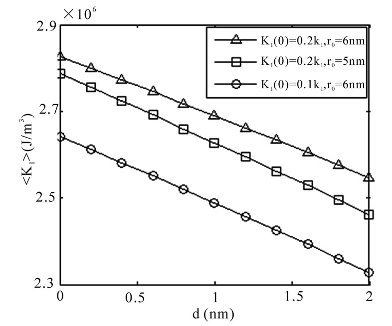
Figure 3. Dependences of average anisotropy,
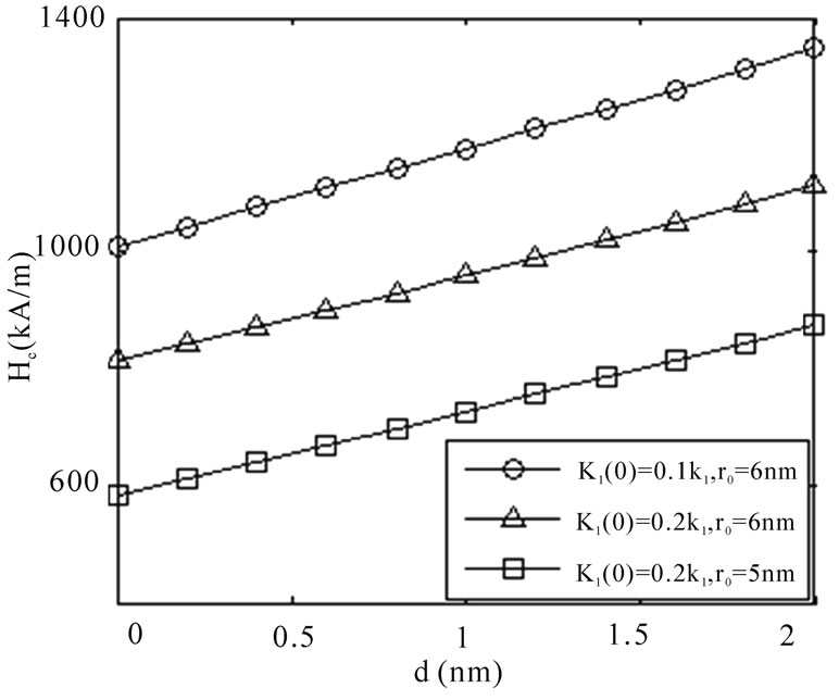
Figure 4. Dependence of Coercivity, Hc, on d for different values of r0 and K1(0)
ascribing to the variation speeds of K1'(r) decrease with increasing r0 (as shown in Figure 2).Thus,
Figure 4 shows the dependence of coercivity, Hc, on d for different values of r0 and K1(0). For different values of r0 and K1(0), Hc increases with increasing d. On the one hand, this is owing to that the enhancement of d results in the reduction of  is larger than that of
with increasing r0. Consequently, Hc computed by Equation (4) increases. When r0 = 6 nm, d =1 nm and K1(0) = 0.15K1, the calculated coercivity is 1068 kA/m, which is consistent well with the experimental data (IP’s thickness of the HDDR Nd-Fe-B magnet is around 1 nm, and its coercivity is 1058 kA/m) reported by Nakayama et al [8].
In summary, the weak magnetic intergranular phase (IP) existing between adjacent grains weakens the IECI. The increase of both the IP’s thickness d and GBSD’s thickness r0 or the decrease of the IP’s anisotropy constant K1(0) all enhance the coercivity of magnet. Yet, if d and r0 are too larger and K1(0) is too smaller, the magnetization and remanence would badly fall, then it is impossible to obtain high-energy product. In order to get high-energy product, it needs not only to enhance coercivity, but also to keep a sufficiently high remanence. Therefore, it is necessary to ensure that the IP’s thickness is around 1 nm, the GBSD’s thickness is around 6 nm, and K1(0) varies between 0.1 K1 and 0.2 K1, by reasonably adjusting the alloy’s composition and technical process. So, this paper possesses a high preference value for experiment preparing high coercivity HDDR Nd-Fe-B magnet with considerable magnetization and remanence.
5. Conclusions
Effects of the IP’s thickness d, its anisotropy constant K1(0), and the GBSD’s thickness r0 on the coercivity in the HDDR Nd-Fe-B magnet are investigated. The results indicate that Hc increases with the increasing d and r0, but decreases with the increasing K1(0). And while r0 = 6 nm, d =1 nm and K1(0) = 0.15K1, the calculated coercivity is consistent well with experimental data.
7. Acknowledgements
The work is supported by the National Natural Science Foundation of China (50671055) and (50801043).
REFERENCES
- H. Nakamura, R. Suefuji, S. Sugimoto, M. Okada, and M. Homma, “Effects of HDDR treatment conditions on magnetic properties of Nd-Fe-B anisotropic powders,” Journal Applied Physics, Vol. 76, No. 10, pp. 6828–6830, November 1993.
- M. Sagawa, S. Fujimura, H. Yamamoto, Y. Matsuura, and K. Hiraga, “Permanent magnet materials based on the rare earth-iron-boron tetragonal compounds,” IEEE Transactions on Communications, Vol. 20, No. 1, pp. 1584– 1589, January 1984.
- R. K. Mishra, “Microstructure of melt-spun Nd-Fe-B magnequench magnetis,” Journal of Magnetism and Magnetic Materials, Vol. 54, No. 1, pp. 450–456, February 1986.
- M. Liu, Y. Sun, G. B. Han, Wu. Y, and R. W. Gao, “Dependence of anisotropy and coercivity on microstructure in HDDR Nd-Fe-B magnet,” Journal of Alloys Compounds, Vol. 478, pp. 303–307, April 2009.
- T. Takeshita and R. Nakayama, “Magnetic properties and microstructures of the NdFeB magnet powder produced by hydrogen treatment,” Proceedings of the 10th International Workshop on Rare-Earth Magnets and Their Applications, Kyoto, Japan, pp. 551, 1989.
- T. Takeshita, K. Morimoto, “Anisotropic Nd-Fe-B bonded magnets made from HDDR powders,” Journal Applied Physics, Vol. 79, No. 8, pp. 5040–5044, April 1996.
- R. W. Gao, J. C. Zhang, and D. H. Zhang, “Dependence of the magnetic properties on the alignment magnetic field for Nd-Fe-B bonded magnets made from anisotropic HDDR powders,” Journal of Magnetism and Magnetic Materials, Vol. 191, No. 1, pp. 97–100, January 1999.
- R. Nakayama, T. Takeshita, and M. Itakura, “Microstructures and crystallographic orientation of crystalline grains in anisotropic Nd-Fe-Co-B-(Ga or Zr) magnet powders produced by the hydrogenation-decomposition-desorption-recombination process,” Journal Applied Physics, vol. 76, No. 1, pp. 412–417, July 1994.
- Q. G. Ji, B. X. Gu, J. R. Zhang, Z. J. Tian, Y. W. Du, “Effects of aging at room temperature on as-spun NdFe B/a-Fe nanocomposite magnets,” Journal of Magnetism and Magnetic Materials, Vol. 288, No. 2, pp. 84–91, January 2005.
- J. Fidler and T. Schrefl, “Overview of Nd-Fe-B magnets and coercivity,” Journal Applied Physics, Vol. 79, No. 2, pp. 5029–5034, September 1996.
- M. Yue, X. B. Liu, Y. F. Xiao, and J. X. Zhang, “Magnetization reversal mechanism of anisotropic HDDR Nd2Fe14B-based magnet powder,” Journal of Magnetism and Magnetic Materials, Vol. 269, No. 2, pp. 227–230, February 2004.
- H. Kronmller, K. D. Durst, and M. Sagawa, “Analysis of the magnetic hardening mechanism in RE-Fe-B permanent magnets,” Journal of Magnetism and Magnetic Materials, Vol. 74, No.3, pp. 291–302, February 1988.
- H. Kronmller, M. Fischer, and R. Seeger, “Micromagnetism and microstructure of hard magnetic materials,” Journal Physics D, Vol. 29, No. 2, pp. 2274–2283, January 1996.
- M. Sagawa and S. Fujimura, “New material for permanent magnets on a base of Nd and Fe,” Journal Applied Physics, Vol. 55, No. 6, pp. 2083–2087, March 1984.
- G. B. Han and R. W. Gao, “Effect of exchange-coupling interaction on the effective anisotropy in nanocrystalline Nd2Fe14B material,” Journal of Magnetism and Magnetic Materials, Vol. 281, No. 1, pp. 6–10, October 2004.
- M. GrÄonefeld and H. Kronmller, “Calculation of strayfields near grain edges in permanent magnet material,” Journal of Magnetism and Magnetic Materials, Vol. 80, No. 2, pp. 223–228, August 1989.