Journal of Water Resource and Protection
Vol.08 No.12(2016), Article ID:71887,17 pages
10.4236/jwarp.2016.812090
Control of Seepage through Earth Dams Based on Pervious Foundation Using Toe Drainage Systems
Magdy M. Aboelela
Irrigation Engineering and Hydraulics Department, Faculty of Engineering, Alexandria University, Alexandria, Egypt

Copyright © 2016 by author and Scientific Research Publishing Inc.
This work is licensed under the Creative Commons Attribution International License (CC BY 4.0).
http://creativecommons.org/licenses/by/4.0/


Received: September 28, 2016; Accepted: November 7, 2016; Published: November 10, 2016
ABSTRACT
Many dangerous effects arise from seepage through earth dams based on pervious layer. Therefore, the dam embankment must be provided with seepage control measures to avoid such effects. In the present work, different control methods were used such as flat slopes, toe drainage systems, and a catch drain in the tail water. The hydraulic performance of each control measure was evaluated using the analytical solutions, previously developed, to estimate the seepage quantity (q), the height of seepage surface (h3), and the coordinates of the free surface (hx). Study was conducted on a physical model for a dam embankment having a top width (b) = 10.0 meter, height (Hd) = 30.0 meter, and slope factor (m) = 1.5. The obtained results were analyzed and presented in dimensionless charts. Results showed that, the used control measures possess a great effect on the characteristics of seepage through earth dams based on pervious foundations. A comparative study was conducted between the studied toe drainage systems to enable the designers the better choice for design purposes.
Keywords:
Earth Dam, Pervious Foundation, Pipe Drainage, Drainage Banquette, Inclined Drainage, Catch Drain, Seepage Discharge

1. Introduction
Two basic problems grow out of seepage through earth dams. The first is concerned with estimation of the amount of seepage discharge which is often a great economic matter for storage dams. The second focuses on stability of dam embankment against excessive gradients that may washout the soil particles along the seepage surface, on the downstream slope of dam embankment, which may threaten its stability.
Earth dams may be constructed on impervious or pervious foundation, according to the nature of site geological formation. In both cases, the dam must be safeguard against dangerous seepage effects through it. Different control measures were presented by Sasi [1] to protect dams based on impervious foundation. As for earth dams based on pervious foundation, the present paper focuses on analyzing the hydraulic performance for some control measures, using analytical solutions presented in the previous studies.
Central core or upstream impervious blanket is provided to reduce the quantity of seepage and to lower the free surface position. However, toe drainage systems must be used to safeguard the earth dam toe against failure where allow seepage to pass without soil particles. Such toe drainage systems must be used whatever central core or upstream impervious blanket is provided.
In the present paper, toe drainage systems are considered as a control measures for seepage through earth dams based on pervious foundation. Toe drainage systems may cause a slight increase in the seepage quantity in some cases, but lower the free surface to a great extent. The toe drainage systems, considered in the present work, are pipe drainage, drainage banquette, inclined drainage, and catch drain in tail water.
The purpose of the present research is to analyze and evaluate the hydraulic performance of the considered toe drainage systems using the analytical solutions previously developed by Grishin [2] , and Nedrigy [3] [4] [5] . The hydraulic performance of toe drainage systems was evaluated considering the case of earth dam without control measures which considered the reference case to be used as a base of comparison between toe drainage systems. The case of dry downstream condition was considered in calculation where gives the maximum effective head (H), hence, H = h1. Results were presented in a dimensionless form where the seepage discharge is expressed as (q/kdH), and the height of seepage surface length is expressed as (h3/H).
In the following sections, the hydraulic performance of the considered toe drainage systems is explained.
2. Homogeneous Embankment without Toe Drainage Systems
A purely homogeneous dam, which is composed of one kind of material only, is considered in the analyses. An analytical solution that solves the problem of the seepage through an earth dam based on pervious base, as shown in Figure 1, was presented by Grishin [2] . Results of this case were considered as a reference data to be used for comparison between the different toe drainage systems. The embankment slopes must be relatively flat to avoid sloughing of the upstream face due to rapid drawdown of water surface in the dam reservoir. On the other hand, the downstream face must be safeguard against sliding wherever the probable slip circle is existed.
U.S. Army Corps of Engineers [6] recommended an embankment slope factor (m) ranges between 8.0 - 10.0 to avoid the above dangerous effects. Therefore, in the present study, different values of slope factor (m) were tested, applying Grishin solution [2] , to declare the resulted effects on the characteristics of seepage through and beneath the dam embankment, considering the depth of pervious layer (T) = 0.5 B, and the headwater depth (h1) = 0.25 B, where B is base width of embankment.
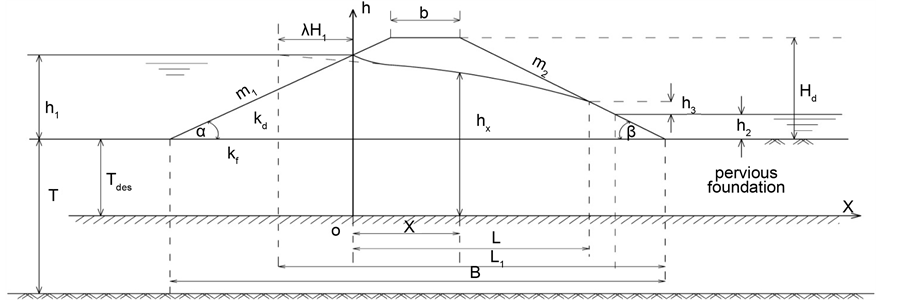
Figure 1. Seepage through homogeneous earth dam and based on pervious foundation, Grishin solution.
The seepage discharge per unit width through a homogeneous earth dam was calculated by Grishin solution [2] as follows:
 (1)
(1)
where h1 is the headwater depth, h2 is the tail water depth, h3 is the vertical height of seepage surface, kd is the coefficient of permeability of the dam material, Tdes is the design depth of the pervious layer (Tdes equals the lowest value of T or Ta, where T is the actual depth of the pervious layer, and Ta is the depth of the active zone of seepage,
where ), and kf is the coefficient of permeability of the pervious foundation
material.
Other notations are shown as follows:
 (2)
(2)
 (3)
(3)
 (4)
(4)
 (5)
(5)
where m1 is the upstream slope factor (m1 = cotα), m2 is the downstream slope factor (m2 = cotβ), where α and β are angles of the upstream and downstream slopes of the dam, respectively, b is the top width of dam, and Hd is the dam height.
The height of the seepage surface (h3) was calculated as follows:
 (6)
(6)
where
 (7)
(7)
The locus of the free surface was determined from the equation:
 (8)
(8)
The free surface within the distance , as shown in Figure 1, is fictitious, to correct it, a line smoothly connecting with curve, constructed by using Equation (8), is drawn.
3. Modified Homogeneous Embankment
A completely homogenous dam embankment, with flatter slopes, may reduce seepage discharge, but at the same time increases volume of the dam material to a large extent. Therefore, the dam embankment must be provided with toe drainage systems to reduce construction costs of the dam. In this case, the dam is called a modified homogeneous embankment. Toe drainage systems include pipe drainage, drainage banquette, inclined drainage, and catch drain in tail water. The hydraulic performance of such control measures is presented in the following sections.
3.1. Pipe Drainage
Pipe drainage is commonly installed along the downstream toe of earth dam as shown in Figure 2. Considering dry downstream condition, Nedrigy [5] presented an analytical solution for seepage through an earth dam, with pipe drainage, based on pervious foundation.
The seepage discharge per unit width through an earth dam, with a pipe drainage, was calculated using Nedrigy solution [5] as follows:
 (9)
(9)
where , and
, and .
.
The locus of the free surface between the vertical sections (o-h) and (1-1) was determined from the equation:
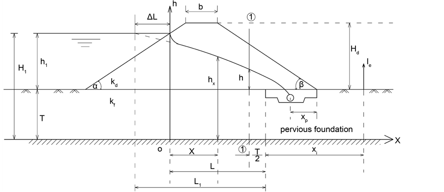
Figure 2. Seepage through earth dam with a pipe drainage and based on pervious layer, Nedrigy solution.
 (10)
(10)
The height of free surface at the vertical section (1-1) (h) was determined from the equation:
 (11)
(11)
The locus of the free surface between the vertical section (1-1) and the pipe drainage was determined from the equation:
 (12)
(12)
where x is the distance measured from the origin of the coordinates (point o).
The exit gradient at the downstream toe ( ) was calculated as follows:
 (13)
(13)
where xi is the distance at which the exit gradient is to be defined.
3.2. Drainage Banquette
Nedrigy [5] developed a solution to define the seepage discharge per unit width through an earth dam, with a drainage banquette, as shown in Figure 3 as follows:
 (14)
(14)
where ,
,  ,
,  , and
, and  is the banquette slope.
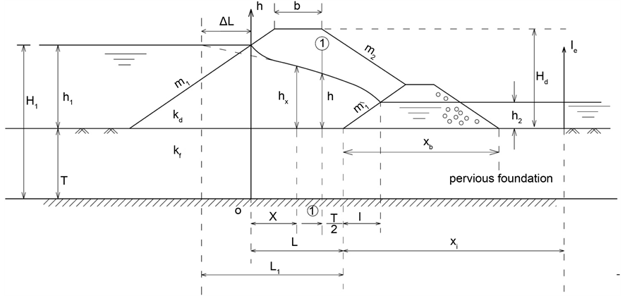
Figure 3. Seepage through earth dam with a drainage banquette and based on pervious layer, Nedrigy solution.
The locus of the free surface between the vertical sections (o-h) and (1-1) was determined from the equation:
 (15)
(15)
The locus of the free surface between the vertical section (1-1) and the banquette was determined from the equation:
 (16)
(16)
where x is the distance measured from the origin of the coordinates (point o).
The height of the free surface at the vertical section (1-1) (h) was determined as follows:
 (17)
(17)
The exit gradient at the downstream toe ( ) was calculated as follows:
 (18)
(18)
where xi is the distance at which the exit gradient is to be defined.
3.3. Inclined Drainage
Nedrigy [5] presented an analytical solution for the seepage through an earth dam, with an inclined drainage, as shown in Figure 4.
Considering the existence of tail water, the seepage discharge per unit width through the earth dam section was calculated, using Nedrigy solution [5] , from the equations:
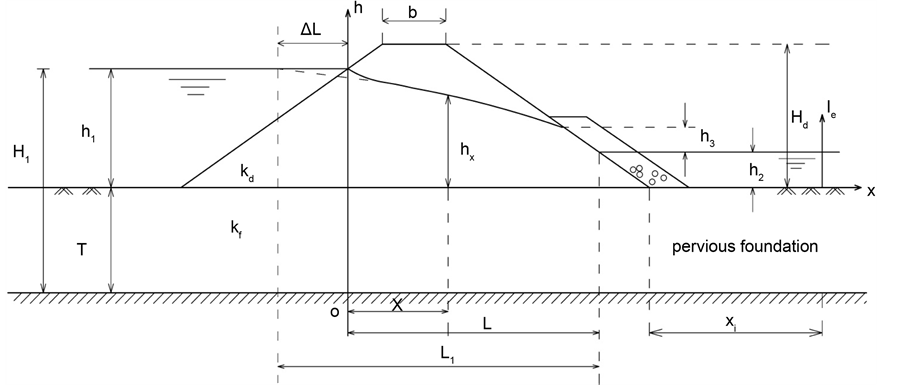
Figure 4. Seepage through earth dam with an inclined drainage and based on pervious layer, Nedrigy solution.
 (19)
(19)
and
 (20)
(20)
where ,
,  , and
, and .
.
The locus of the free surface was determined as follows:
 (21)
(21)
where x is the distance measured from the origin of the coordinates (point o).
The exit gradient at the downstream toe ( ) was calculated as follows:
 (22)
(22)
where xi is the distance at which the exit gradient is to be defined.
3.4. Catch Drain in Tail Water
Grishin [2] obtained a solution to define the seepage through an earth dam with a catch drain in tail water as shown in Figure 5.
The seepage discharge per unit width through the earth dam section was calculated, by Grishin solution [2] , as follows:
 , (23)
and
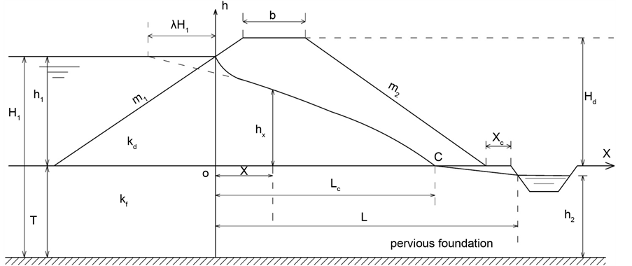
Figure 5. Seepage through earth dam with a catch drain in tail water and based on pervious layer, Grishin solution.
 (24)
(24)
where Lc is the distance at which the free surface intersects the dam base, and h2 is the vertical distance between water level in the catch drain and end of the pervious layer as shown in Figure 5.
The locus of the free surface from the vertical section (o-h) and point (C) was determined from the equation:
 (25)
(25)
The locus of the free surface from point (C) and the catch drain was determined from the equation:
 (26)
(26)
where x is the distance measured from the origin of the coordinates (point o).
4. Analysis and Discussion
In the present section, the above mentioned analytical equations are applied to determine the seepage characteristics for each of the considered toe drainage systems.
In the calculation procedure, both the coefficient of permeability for the dam embankment (kd) and the foundation (kf) are considered the same, i.e. (kd = kf). In addition, the case of dry downstream condition was accounted for (h2 = 0.0) to give the maximum effective head (H).
4.1. Homogeneous Earth Dam Embankment
4.1.1. Effect of Slope Factor (m)
Applying Equations (1), and (6) on the considered model, using different values of the slope factor (m), the values of seepage parameters (relative seepage discharge (q/KdH), and relative height of seepage surface (h3/H)) were graphically presented in Figure 6. It can be noticed that, increasing the slope factor (m) from 1.5 to 4.0 results in a rapid decrease in values of (q/KdH), beyond which small effect exists. Thus, the reduction percentage in values of (q/KdH) due to increasing value of (m) from 1.5 to 4.0 is about 50.0%, while the resulted reduction due to increasing value of (m) from 1.5 to 8.0 is about 70.0%. This insures that, value of slope factor (m) higher than 4.0 is considered useless taking into consideration the huge increase in volume of the dam material for value of slope factor (m) higher than 4.0.
It can be noticed that, increasing the value of slope factor (m) from 1.5 to 8.0 results in a small decrease in values of (h3/H).
Increasing the value of dam slope factor (m) from 1.5 to 4.0 resulted in an increase of the dam material volume by about 140.0%, while it reaches about 360.0% for increasing the value of (m) from 1.5 to 8.0. This means that, homogeneous dam with flat slopes, however, reduces seepage quantities, the volume of dam materials is increased to a large extent. Such a conclusion was confirmed by USBR [7] , where the maximum value of the slope factor (m) was determined equal to 4.0.
Using Equation (8), the coordinates of the free surface for homogeneous earth dam based on pervious foundation were determined, as given in Figure 7, for m1 = m2 = 1.5, (T/B) = 0.5, and (H/B) = 0.25.
4.1.2. Effect of Pervious Layer Depth (T)
The effect of the pervious layer depth (T), on the seepage parameters ((q/KdH), (h3/H)), was analyzed using different relative values of (T/B), as presented in Figure 8. It is clear that, increasing the relative depth of the pervious foundation (T/B) from 0.10 to 0.50, results in a rapid increase in values of (q/KdH) beyond which, these values gradually increase. The percentage of increase in (q/KdH) due to increasing value of (T/B) from
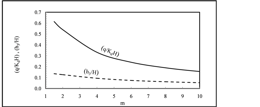
Figure 6. Variation of seepage parameters ((q/KdH), (h3/H)) with the slope factor (m) for homogeneous earth dam for (T/B) = 0.5, and (H/B) = 0.25.
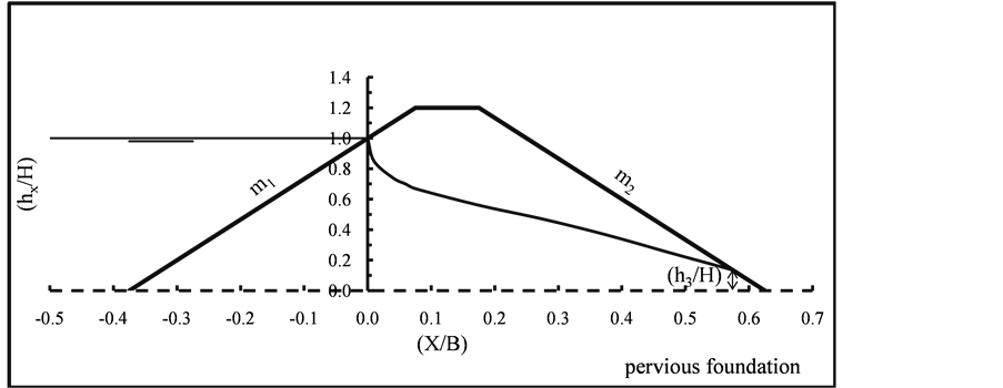
Figure 7. Free surface through homogeneous earth dam based on pervious foundation for m1 = m2 = 1.5, (T/B) = 0.5, and (H/B) = 0.25.
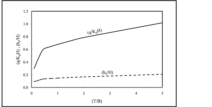
Figure 8. Variation of seepage parameters ((q/KdH), (h3/H)) with relative depth of the pervious foundation (T/B) for homogeneous earth dam for m1 = m2 = 1.5, and (H/B) = 0.25.
0.10 to 0.50 is about 110.0%, while the resulted increase is about 245.0% for value of (T/B) ranges from 0.10 to 5.0. Increasing the relative depth of the pervious foundation (T/B) results in a slight increase in values of (h3/H).
4.2. Modified Homogeneous Embankment
As mentioned above, the modified homogeneous embankment is that provided with toe drainage systems. The hydraulic performance of the different toe drainage systems was analyzed as given in the following sections.
4.2.1. Pipe Drainage System
Applying Equations (9), and (11) on the considered model, the effect of the pipe drainage location (Xp) on the seepage parameters ((q/KdH), (h/H)), was studied according to different values of the relative pipe location (Xp/B) = 0.025, 0.10, 0.15, 0.20, 0.25, and 0.30. Using Equations (10), and (12), the coordinates of the free surface for the considered earth dam model were determined, as shown in Figure 9, for m1 = m2 = 1.5, (T/B) = 0.5, and (H/B) = 0.25. The relative pipe location (Xp/B) = 0.025 presents the minimum location of the pipe drainage at which the free surface just touches the downstream slope of embankment. Considering different values of (Xp/B), the corresponding values of the relative seepage discharge (q/KdH), and the relative height of free surface at section (1-1) (h/H) for m1 = m2 = 1.5, (T/B) = 0.5, and (H/B) = 0.25 were graphically presented in Figure 10. The percentage of increase in value of (q/KdH), compared to the reference value for homogeneous embankment, (q/KdH) = 0.614, ranges from about 7.0% for value of (Xp/B) = 0.10 to about 35.0% for value (Xp/B) = 0.30.
It is seen that, values of (q/KdH), and (h/H) increase with increasing the relative pipe drainage location (Xp/B).
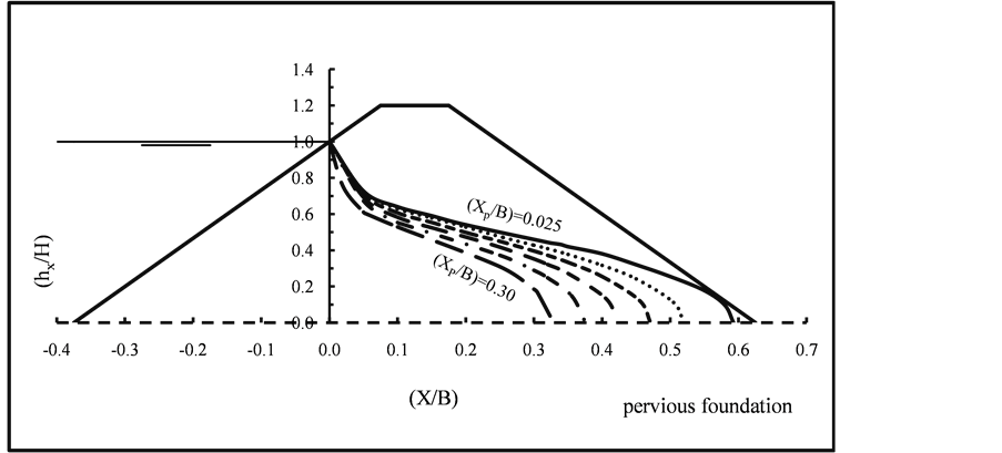
Figure 9. Free surface through modified earth dam with pipe drainage for different values of the relative location (Xp/B) for m1 = m2 = 1.5, (T/B) = 0.5, and (H/B) = 0.25.

Figure 10. Variation of (q/KdH), and (h/H) with relative location of the pipe drainage (Xp/B) for m1 = m2 = 1.5, (T/B) = 0.5, and (H/B) = 0.25.
4.2.2. Drainage Banquette System
Applying Equations (14), and (17) on the considered earth dam model, the effect of the drainage banquette length (Xb) on the seepage parameters was studied using different values of (Xb/B) = 0.03, 0.05, 0.10, 0.20, 0.25, 0.30, and 0.35 for m1 = m2 = 1.5, (T/B) = 0.5, and (H/B) = 0.25. Using Equations (15), and (16), the coordinates of the free surface for the considered model were determined, as shown in Figure 11, for m1 = m2 = 1.5, (T/B) = 0.5, and (H/B) = 0.25. The value of (Xb/B) = 0.03, presents the minimum length of the banquette at which the free surface just touches the downstream slope of embankment. Considering different values of (Xb/B), the corresponding values of the relative seepage discharge (q/KdH), and the relative height of free surface at section (1-1) (h/H) were graphically presented in Figure 12.
It is seen that, values of (q/KdH), and (h/H)increase with increasing the banquette length (Xb/B). The percentage of increase in value of (q/KdH), compared to the reference value for homogeneous embankment, (q/KdH) = 0.614, ranges from about 1.0% for value of (Xb/B) = 0.05 to about 45.0% for value of (Xb/B) = 0.35.
4.2.3. Inclined Drainage System
Applying Equations (19), and (20) on the considered model, the relative seepage discharge
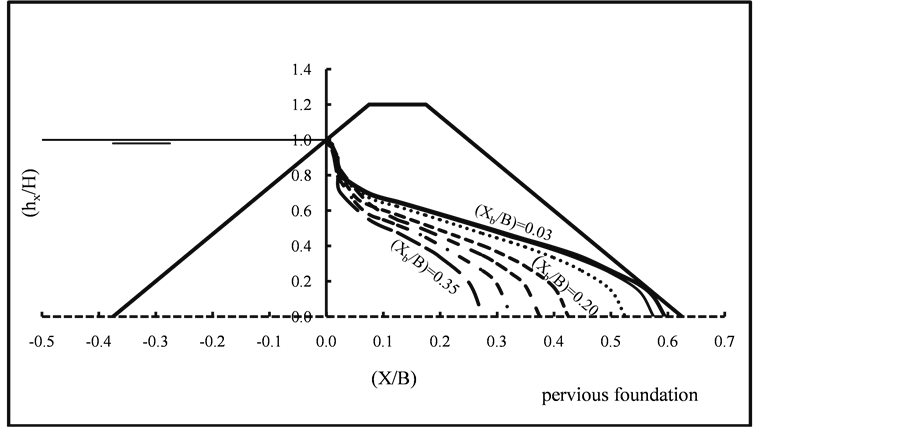
Figure 11. Free surface through modified earth dam with drainage banquette for different values of the relative banquette length (Xb/B) for m1 = m2 = 1.5, (T/B) = 0.5, and (H/B) = 0.25.
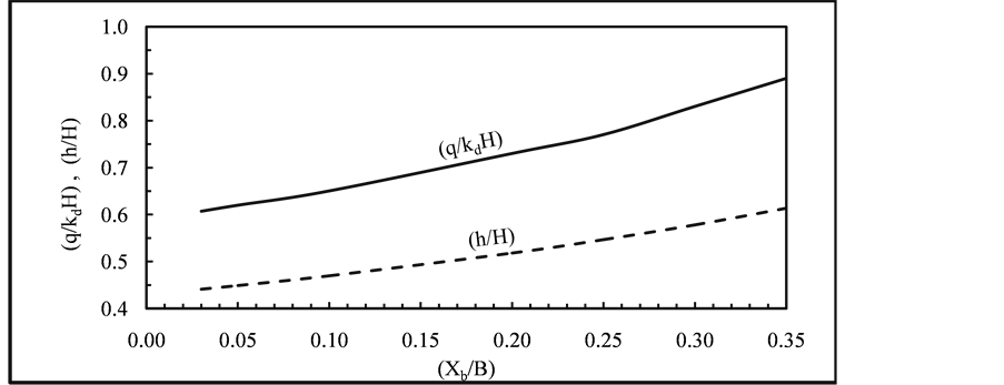
Figure 12. Variation of (q/KdH), and (h/H) with the relative banquette length (Xb/B) for m1 = m2 = 1.5, (T/B) = 0.5, and (H/B) = 0.25.
(q/KdH) and the relative height of the seepage surface (h3/H) were calculated for m1 = m2 = 1.5, (T/B) = 0.5, and (H/B) = 0.25. The resulted value of (q/KdH) = 0.573, and the value of (h3/H) = 0.296. These values were compared to the reference values for homogeneous embankment, (q/KdH) = 0.614, and (h3/H) = 0.136. It is obvious that, value of (q/KdH) decreased by about 7.0% while value of (h3/H) increased by about 120.0%.
Applying Equation (21), the coordinates of the free surface for the considered modified earth dam with inclined drainage were determined, as shown later, for m1 = m2 = 1.5, (T/B) = 0.5, and (H/B) = 0.25.
4.2.4. Catch Drain System in Tail Water
Applying Equations (23), and (24) on the considered model, the effect of the catch drain location (Xc) on the seepage discharge (q), was studied according to different values of the relative location of the catch drain (Xc/B) = 0.0, 0.025, 0.05, and 0.0575 for m1 = m2 = 1.5, (T/B) = 0.5, and (H/B) = 0.25. The resulted values of the relative seepage discharge (q/KdH), and the relative distance at which the free surface intersects the dam base (Lc/B) are shown in Figure 13. It is seen that, value of the relative seepage discharge (q/KdH) decreases with increasing the catch drain location (Xc/B), while value of (Lc/B) increases. The values of (q/KdH) for different values of (Xc/B) were compared to the reference value for homogeneous embankment, (q/KdH) = 0.614. It is obvious that, for value of (Xc/B) = 0.0, value of (q/KdH) increased by about 55.0%.
Applying Equations (25) and (26), the coordinates of the free surface for the considered modified earth dam with catch drain in tail water were determined, as shown in Figure 14, for m1 = m2 = 1.5, (T/B) = 0.5, and (H/B) = 0.25. The value of (Xc/B) = 0.0, presents the minimum location of the catch drain at which (Lc/B) = 0.5736, and (q/KdH) = 0.937. The value of (Xc/B) = 0.0575, presents the maximum location of the catch drain at which the free surface passes through the toe point, (Lc/B) = 0.6235, and (q/KdH) = 0.871. It is obvious that, for (Xc/B) = 0.0575, value of (q/KdH) increased by
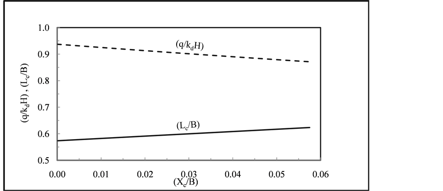
Figure 13. Variation of (q/KdH) and (Lc/B) with relative location of the catch drain (Xc/B) for m1 = m2 = 1.5, (T/B) = 0.5, and (H/B) = 0.25.
about 45.0%.
4.3. Comparison between Homogeneous and Modified Homogeneous Earth Dam Embankments
4.3.1. Seepage Discharge
The hydraulic performance of the toe drainage systems was analyzed. A comparison between the considered systems was conducted to indicate the effectiveness of each system on the seepage parameters.
The free surfaces through homogeneous and modified earth dams are shown in Figure 15 for m1 = m2 = 1.5, (T/B) = 0.5, and (H/B) = 0.25. It is seen that, the free surfaces for the toe drainage systems are nearly close to each other and slightly lie above the free surface for the homogeneous dam.
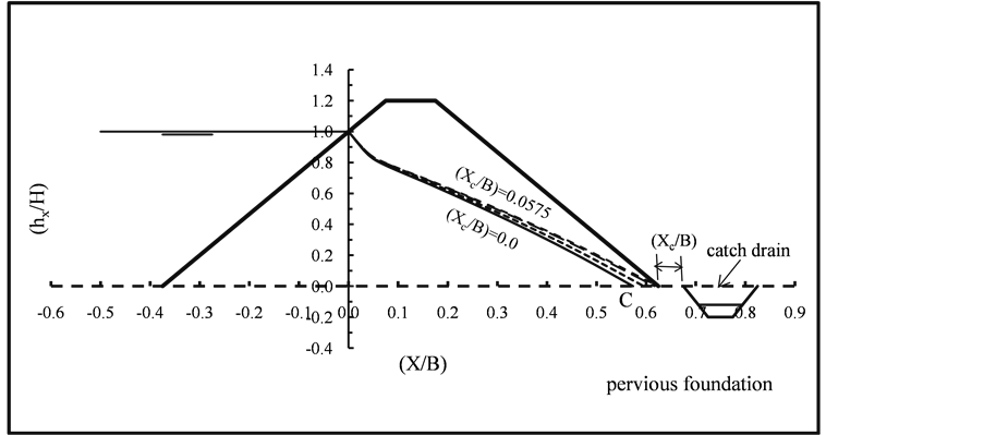
Figure 14. Free surface through modified earth dam with catch drain in tail water for different values of the relative location (Xc/B) for m1 = m2 = 1.5, (T/B) = 0.5, and (H/B) = 0.25.
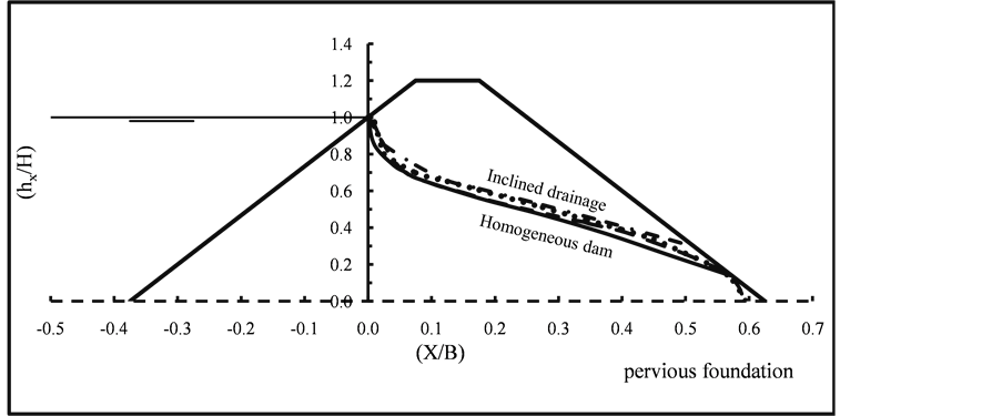
Figure 15. Free surfaces through homogeneous and modified earth dams for m1 = m2 = 1.5, (T/B) = 0.5, and (H/B) = 0.25.
The variation of (q/KdH) with relative depth of the pervious foundation (T/B) for homogeneous and modified earth dams are illustrated in Table 1 and Figure 16 for m1 = m2 = 1.5, and (H/B) = 0.25. It is clear that, the relative seepage discharge (q/KdH) linearly increases with increasing the relative depth of pervious foundation (T/B) for the homogeneous as well as for the modified embankments. It is noticed that, value of (q/KdH) for pipe, banquette, and inclined drainage are nearly close to each other, but for catch drain, it is greatly higher. It is also found that value of (q/KdH) for both pipe drainage and drainage banquette are nearly the same.
4.3.2. Exit Gradient
Exit gradient (Ie) for seepage through embankment and foundation at or near the

Table 1. Values of (q/KdH) corresponding to relative depth of the pervious foundation (T/B) for homogeneous and modified earth dams for m1 = m2 = 1.5, and (H/B) = 0.25.
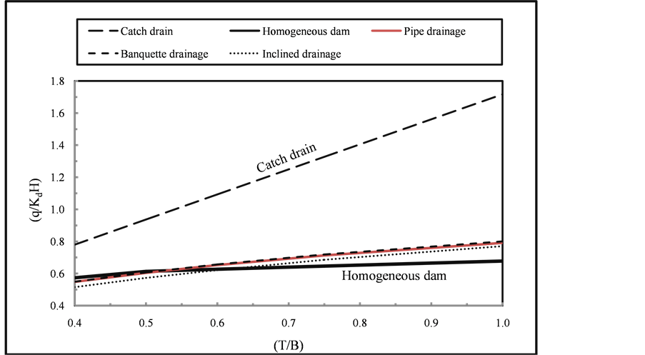
Figure 16. Variation of (q/KdH) with relative depth of the pervious foundation (T/B) for homogeneous and modified earth dams for m1 = m2 = 1.5, (T/B) = 0.5, and (H/B) = 0.25.
downstream toe was analyzed. If the exit gradient is greater than the critical gradient (Ic), the piping phenomenon may exist which can lead to undermining and loss of the dam. Harr, M. E. [8] [9] recommended a ranges for the factor of safety for exit gradient (F.O.S = (Ic/Ie)) to be 4 - 5.
Using Equations (13), (18), and (22), the relative exit gradient (Ie∙(B/H)) was estimated and graphically presented, as shown in Figure 17, for toe drainage systems; pipe drainage, drainage banquette, and inclined drainage. Values of the relative exit gradient (Ie∙(B/H)), for pipe drainage, were calculated corresponding to the relative distance (Xi/B) for relative location of the pipe drainage (Xp/B) = 0.025, m1 = m2 = 1.5, (T/B) = 0.5, and (H/B) = 0.25. For drainage banquette, values of (Ie∙(B/H)) were estimated for relative length of the drainage banquette (Xb/B) = 0.03. It is clear that, values of (Ie∙(B/H)) decrease with increasing values of (Xi/B). It is obvious that, values of (Ie∙(B/H)) for both pipe drainage and drainage banquette systems are nearly the same. As for inclined drainage system, values of (Ie∙(B/H)) are slightly less, especially for low values of (Xi/B).
5. Conclusions
The present study focuses on evaluation of the hydraulic performance of the different control measures used to protect earth dams, based on pervious foundation, against seepage. Various control measures were tested such as; flat slopes, toe drainage systems, and a catch drain in tail water. The hydraulic performance of each control measure was evaluated; using the analytical solutions previously developed, to determine the relative seepage discharge (q/KdH), the relative height of seepage surface (h3/H), the relative coordinates of the free surface through earth dams (hx/H), and the exit gradient (Ie) at the downstream toe. The evaluation was conducted by comparing values of the seepage parameters obtained by the control measures with those obtained from the reference case (homogeneous dam without any control measures).
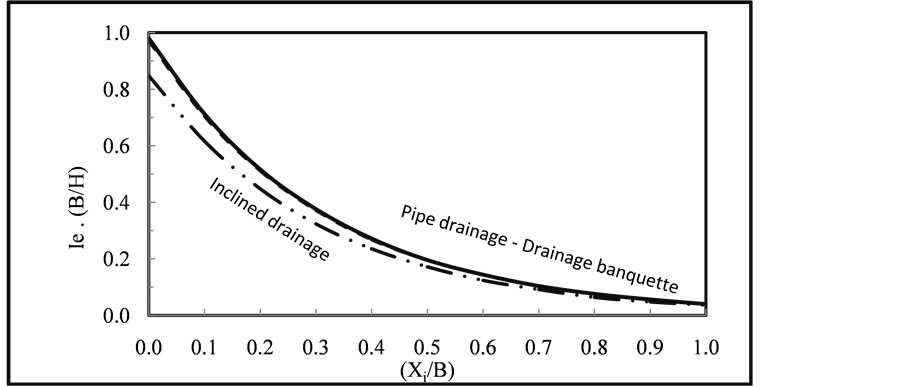
Figure 17. Variation of relative exit gradient (Ie∙(B/H)) with relative distance (Xi/B) for modified earth dam with pipe drainage ((Xp/B) = 0.025), drainage banquette ((Xb/B) = 0.03), and inclined drainage for m1 = m2 = 1.5, (T/B) = 0.5, and (H/B) = 0.25.
As a result of the above analysis, the conclusions of the present study are arranged as follows:
1) Increasing the relative depth of the pervious foundation (T/B), for the homogeneous earth dam, from 0.10 to 0.50 results in a rapid increase in values of (q/KdH) beyond which, gradually increase exists. Increasing the relative depth of the pervious foundation (T/B) results in a slight increase in values of (h3/H).
2) A flat slope for the homogeneous embankment is not desired control measure where it increases cost of the dam construction to a large extent.
3) For the homogeneous earth dam based on pervious foundation, the slope factor (m) higher than 4.0 is considered useless.
4) Values of the relative seepage discharge through earth dam based on pervious foundation (q/KdH) increase with increasing the relative location of pipe drainage (Xp/B) and the relative length of drainage banquette (Xb/B). Values of (q/KdH) using pipe drainage, drainage banquette, and inclined drainage are nearly the same but for catch drain, value of (q/KdH)is greatly higher.
5) Values of the relative exit gradient (Ie∙(B/H)) decrease with increasing values of the relative distance (Xi/B). Values of (Ie∙(B/H)) for both pipe drainage and drainage banquette systems are nearly the same. As for inclined drainage system, values of (Ie∙(B/H)) are slightly less, especially for low values of (Xi/B).
Acknowledgements
The author expresses sincere thanks to Prof. Dr. M. A. Abourohim of Irrigation Engineering and Hydraulics Department, Faculty of Engineering, Alexandria University, Egypt, for his giving precious support and helpful discussions.
Cite this paper
Aboelela, M.M. (2016) Control of Seepage through Earth Dams Based on Pervious Foundation Using Toe Drainage Systems. Journal of Water Resource and Protection, 8, 1158-1174. http://dx.doi.org/10.4236/jwarp.2016.812090
References
- 1. Sasi, T.S. (2015) Evaluation of Control Measures for Seepage through Earth Dams based on Impervious Foundation. M.Sc. Thesis, Faculty of Engineering, Al-Mergib University, Libya.
- 2. Grishin, M.M. (1982) Hydraulic Structures. Translated from Russian, Mirpublishers, Moscow.
- 3. Nedrigy, V.P. (1959) Calculation of Seepage through Hydraulic Structures. Gostroyzdat, Moscow.
- 4. Nedrigy, V.P. (1969) Calculation of Seepage through Earth Dams with Toe Drains. Gostroyzdat, Moscow.
- 5. Nedrigy, V.P. (1983) Hydraulic Structures. Gostroyzdat, Moscow.
- 6. U. S. Army Corps of Engineers (1986) Seepage Analysis and Control for Dam. Washington, DC.
- 7. United States Department of the Interior, Bureau of Reclamation (2010) Design of Small Dams. A Water Resources Technical Publication, Second Indian Reprint, SBS Publishers & Distributors Pvt. Ltd., New Delhi.
- 8. Harr, M.E. (1962) Groundwater and Seepage. McGraw-Hill Book Company, New York.
- 9. Harr, M.E. (1977) Mechanics of Particulate Media. McGraw-Hill Book Company, New York.