Journal of Biomedical Science and Engineering
Vol.7 No.10(2014), Article
ID:48812,8
pages
DOI:10.4236/jbise.2014.710084
Endotension Distribution in Fluid-Structure Interaction Analysis of Abdominal Aortic Aneurysm Following Endovascular Repair
Zeinab Hooshyar1, Hadi Fakhrabadi1, Somayeh Hooshyar2, Alireza Mehdizadeh3
1Mechanical Engineering, Shiraz University, Shiraz, Iran
2Department of Midwifery, Shiraz University, Shiraz, Iran
3Department of Medical Physics, School of Medicine, Shiraz University of Medical Sciences (SUMS), Shiraz, Iran
Email: mehdizade@sums.ac.ir
Copyright © 2014 by authors and Scientific Research Publishing Inc.
This work is licensed under the Creative Commons Attribution International License (CC BY).
http://creativecommons.org/licenses/by/4.0/


Received 13 June 2014; revised 29 July 2014; accepted 14 August 2014
ABSTRACT
Endovascular aneurysm repair is a new and minimally invasive repair for patients with abdominal aortic aneurysm (AAA). However, endotension is one of the post-operative compliances of endovascular aneurysm repair in abdominal aortic aneurysm. Typically, endotension is mainly a result of pressure transmitted to the aneurysm sac through endovascular implanted graft (EVG) by intermediary of the stagnant blood filled aneurysm cavity. Focusing on a representative AAA with an EVG, a fluid-structure interaction (FSI) solver has been employed to provide physical insight for evaluating the blood flow dynamics, maximum AAA-stresses and deformations. Although implanting an EVG can reduce the sac pressure, mechanical stress and wall deformation in AAAs significantly, they remain non-zero. These magnitudes depend on multi-factors including blood flow conditions such as velocity and pressure, as well as EVG and aneurysm geometries. In this study, it was found that blood flow velocity deceleration occurs on the graft due to the curvature of its neck, so greater curvature of the graft neck can contribute to vortex formation in this area and exert load on the graft wall. In the iliac bifurcation region, divaricating of the flow leads to a large net flow momentum change. It results in additional stress on the implant graft and may lead to graft migration. One of the peak wall stress points is in the neck region where the stent-graft is in contact with the aneurysm wall. This necessitates considering adequate graft fixation to withstand the stresses of blood flow through the implanted graft. Also, maximum deformation of sac wall occurs in around the large diameter of the sac, and deformation during the systole phase is higher than that during the diastole phase.
Keywords:Endotension, Fluid-Structure Interaction, Endovascular Repair, Endovascular Implanted Graft

1. Introduction
Abdominal aortic aneurysm (AAA) is a localized dilatation of the abdominal aorta exceeding the normal diameter by more than 50 percent, and is the most common form of aortic aneurysm. Abdominal aortic aneurysms are found in up to 8% of men over the age of 65 years. Rupture of an AAA and its associated catastrophic physiological insult carries an overall mortality in excess of 80%, and 2% of all deaths are AAA-related [1] . The most common treatment for a large (>5 centimeters), unruptured aneurysm is open surgical repair by a vascular surgeon. The aneurysm is cut and sewn in a graft to act as a bridge for the blood flow. The blood flow then goes through the plastic graft and no longer allows the direct pulsation pressure of the blood to further expand the weak aorta wall [2] . Interventional repair is a less invasive method of placing a graft within the aneurysm to redirect the blood flow and stop direct pressure from being exerted on the weak aortic wall. This relatively new method eliminates the need for a large abdominal incision. It also eliminates the need to clamp the aorta during the procedure. Clamping the aorta creates a significant stress on the heart, and people with severe heart disease may not be able to tolerate this major surgery [3] -[6] . The most complicated endovascular post-operation compliance is aneurysm growing even in the absence of endoleak and this is considered to be a treatment failure with the risk of rupture. This condition is described as “endotension” [4] . While the pathophysiology of other endovascular post-operation compliance is beginning to be elucidated, controversy still exists about the etiology and clinical consequences of endotension.
Basically, when the stress in the vessel wall exceeds that of the wall strength, rupture occurs. Peak stress was found significantly higher in the ruptured AAA than in the non-ruptured one. Implanting an EVG reduces the sac pressure and mechanical stress in AAA significantly but it remains non-zero. Wall stress in AAA is influenced by the aneurysm diameter, shape, wall thickness, wall mechanical properties, the presence of thrombus and blood pressure. Numerical modeling of aneurysms and stent-grafts is a useful method for determining the stresses and forces seen in-vivo. Finite element analysis (FEA) allows the deformations on the aneurysm wall to be determined.
FSIs are increasingly being implemented in the study of vascular diseases and AAAs [7] -[11] . Thubrikar et al. [12] investigated wall stress distributions in three-dimensional models of human abdominal aortic aneurysms based on CT-scans. Chong and How [13] measured the flow patterns in an endovascular stent-graft for abdominal aortic aneurysm repair. They observed that low velocity regions in the main trunk as well as flow separation in the stump region and the curved segment of the iliac limbs were associated with thrombosis in the clinical situation. Volodos et al. [14] investigated forces exerted on the rigid, bifurcated EVG. They found that the iliac bifurcation angle, EVG size and blood pressure impact the migration forces significantly. In summary, most of the research focused on AAA-wall stress or EVG-lumen flow separately, i.e. without consideration of the coupled fluid-structure interactions between the lumen blood, EVG wall, sac stagnant blood, and AAA wall. FSI occurs whenever the problem involves the flow of fluid causing the deformation of a solid structure. This deformation, in turn, changes the boundary conditions of the fluid field. Because blood flow and AAA/EVG are coupled in a complicated way, the pulsatile flow will affect the movement of the AAA/EVG walls and wall motion in turn influences the flow fields, i.e. the lumen and sac blood. The dynamic interaction between the flow and wall may influence the predicted wall stress. Di Martino et al. was the first to consider the dynamics of AAA and installed graft separately and report patient specific wall stress results of coupled fluid-solid interaction (FSI) simulation and suggested that FSI is a useful tool to investigate the physical sight of the blood flow and aneurysm wall rupture [15] .
In this study, the fluid-structure interactions of blood flow, EVG, stagnant sac-blood and aneurysm wall with their realistic properties are simulated demonstrating a representative AAA model of stress distribution in AAA wall; its deformation leads to endotension and hence aneurysm rupture.
2. Materials and Methods
In this study, an iterative two-way coupling method is employed to link the fluid and solid portions. To achieve this, ANSYS 13.0 software package containing the programs ANSYS Workbench and CFX, which are capable of modeling the structural and fluid domains, respectively were used.
2.1. Governing Equations
1) Flow Equations
The blood flow in the vessels is commonly laminar. This is the normal condition for blood flow throughout most of the circulatory system [16] . For unsteady laminar flow of an incompressible and non-Newtonian fluid, the mass and momentum equations (ignoring the body forces) can be written as [17] :
 (1)
(1)
 (2)
(2)
where Ui denotes velocity components, ρ and μ are fluid density and viscosity, respectively, and p is the pressure.
2) Structure Equations
For the vessel wall, which is defined as an elastic solid, the relationship between stress and displacement (ignoring body forces) can be expressed as [17] :
 (3)
(3)
where di and σij are the components of the displacements and stress tensor in solid, respectively, and ρw is the wall density. σij can be obtained from the constitutive equation of the material. For a Hooke an elastic solid, it is as follows:
 (4)
(4)
where λ and μL are the Lame’s constants, δij is the Kronecker delta and eij are the components of the strain tensor which can be expressed as:
 (5)
(5)
Lame’s constants are related to physical material properties, Young’s modulus, E, and Poisson’s ratio, υ, by the following equations:
 (6)
(6)
 (7)
(7)
2.2. Material Properties
The Carreau non-Newtonian model, as used by Cho et al. [18] and Johnston et al. [19] has proved to provide close approximations to experimental blood flow conditions and not over-predict the non-Newtonian effects. The relation between viscosity and shear strain rate,  , can be written as [20] :
 (8)
(8)
where λf = 3.313 s, zero strain viscosity μ0 = 0.056 Pa.s, infinite strain viscosity μ∞ = 0.00345 Pa.s, and the empirical exponent n = 0.3568. Also the blood has a density of 1050 kg/m3.
The aneurysm wall and EVG are considered to be linearly elastic, isotropic and nearly incompressible. The Young’s modulus of 4.66 MPa, Poisson’s ratio of 0.45 and density of 1062 kg/m3 [21] were considered for aneurysm wall. For a bifurcated NiTi-stent interwoven with the graft material, equivalent Poisson’s ratio of 0.27, density of 6000 kg/m3 and Young’s modulus of 10 MPa [22] were assumed.
2.3. Boundary Conditions
A real pulsatile flow velocity and pressure were assumed in the entrance and the iliac outlets of the abdominal aorta respectively with a time period of 0.75 s, as shown in Figure 1 [23] . An appropriate boundary condition is applied on the walls to indicate the interfaces on which FSI occurs. This allows the transfer of fluid forces and solid displacements across the specified boundaries. The solid model corresponding to the vessel walls are assumed to be fixed at the outlet of the renal arteries.
2.4. Geometry
An anatomically realistic model of an abdominal aorta aneurysm is reconstructed from CT-scan images, using Mimics software. Following the CAD profiles, we used GAMBIT 2.3.16 software to build the graft and aneurysm wall, and then imported them into ANSYS 13.0 software package containing the finite element and finite volume-based commercial codes, ANSYS Workbench and CFX. The cavity between EVG and the aneurysm wall was filled with stagnant blood. The interacting materials included the luminal blood, stagnant blood in the AAA cavity and the AAA wall.
It is necessary to have a proper mesh to reflect actual conditions and provide accurate answers while not exceeding reasonable computational power. Due to the geometry complexity, multi-block meshing technique is used to create structured mesh in computational domains and to prevent high grid concentration in the centre of circular cross-sections (as shown in Figure 2).

Figure 1. Time variation of the inlet velocity and outlet pressure.
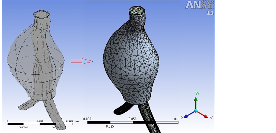
Figure 2. Structured mesh for computational domain.
3. Results and Discussion
In this section, the results for the fluid and solid properties such as velocity and pressure distributions, wall shear stress and deformation of the vessel wall with a period of tp = 0.75 are depicted at selected time frames over cardiac cycle, t/tp = 0.2, t/tp = 0.4 and t/tp = 1.0, which correspond to the maximum, minimum and uniform flow, respectively.
3.1. Velocity
Plots of time-dependent velocity distribution at selected times for the installed graft model are shown in Figure 3. It is observed that the flow has begun to decelerate in the graft neck. The larger velocity deceleration may be due to the greater curvature of the neck of the stent-graft. The greater curvature can contribute to vortex formation in this area [24] which exerts extra load on the graft wall. Also, as it obvious in the iliac bifurcation region, the stream of blood flow divaricates into two branches, which results in a large net momentum change. Actually, this flow stream concentration results in extra stress on the implanted graft which can lead to graft migration [25] . The maximum blood velocity is 7.58 m/s and it occurs in t/tp = 0.2. The amount of velocity in implanted graft is reduced in t/tp = 0.4 and again increased at the end of one fluid pulsatile loading.
3.2. Wall Shear Stress
Wall shear stress plays an important role in the vessel wall behavior in the cases where structural response can be responsible for aneurysm wall rupture. It is obvious that wall shear stress is directly related to the rate of velocity change near the wall, which is caused by the change in geometry. In other words, any change of geometry in the artery produces significant effects on the blood flow. In order to investigate stress on the aneurysm sac wall, Figure 4 shows the wall shear stress variations at selected time frames, t/tp = 0.2, t/tp = 0.4 and t/tp = 1.0. The maximum shear stress is in t/tp = 0.2 i.e. at the beginning of pulsation. Clearly, in all pulsation one of the peak wall stress points is in the neck region where the stent-graft is in contact with the aneurysm wall. It means that adequate fixation should be considered to withstand the stresses of blood flow through the implant graft.
3.3. Deformation
Total deformation of the sac vessel wall is depicted in Figure 5 at two selected time points of the wave, i.e. t/tp = 0.2 and t/tp = 0.4, corresponding to maximum and minimum flow, respectively. It is seen that AAA sac wall is not deformed uniformly in the X-Z plane. Therefore, the aorta wall deformation in Z-direction is more than other directions. The time-dependent deformation is a result of the fluid pulsatile pressure loading via the FSI coupling. The maximum deformation of the sac wall is about 2.1 mm, as shown in Figure 5. Hence, this part is more critical in aneurysm rupture. Also, it is found that wall deformation during systole phase, in which the flow is accelerating, is higher than that in the diastole phase.
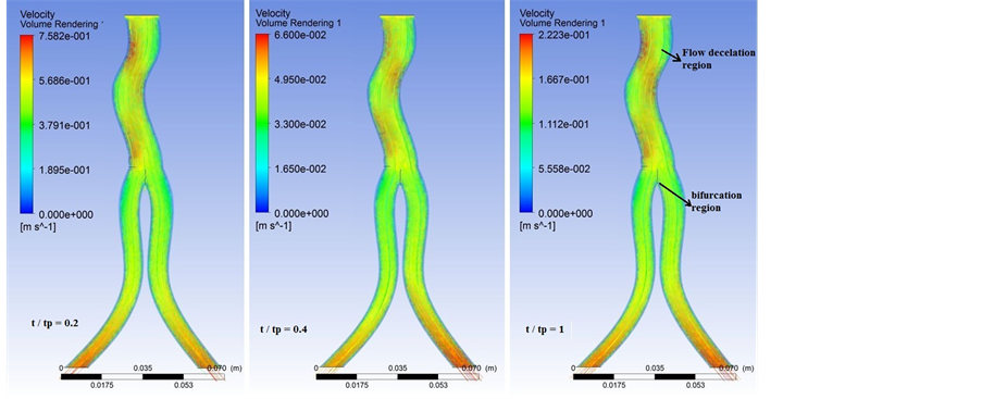
Figure 3. Velocity distribution at selected time frames in the implanted graft.

Figure 4. Wall shear stress (Pa) distributions on the sac wall at t/tp = 0.2, t/tp = 0.4 and t/tp = 1.0.

Figure 5. Contours of the sac wall deformation (m) at two selected time frames.
4. Conclusion
The aim of this study was to provide an understanding on the effects of incorporating FSI into the simulation of endotension distribution in the abdominal aortic aneurysm following endovascular repair. Plots of time-dependent velocity distribution in the installed graft revealed that velocity deceleration occurs due to the curvature of the neck of the stent-graft. Then, greater curvature of the graft neck can contribute to vortex formation in this area and exert extra load on the graft wall. Also, in the iliac bifurcation region, the stream of blood flow divaricates into two branches, which results in a large net momentum change. Actually, this flow stream concentration results in additional stress on the implant graft which can lead to graft migration. These findings showed that incorporating fluid-structure interaction and considering vessel wall deformations in studying blood flow through endovascular graft has significant effects on endotension distribution in the abdominal aortic aneurysm. It is obvious that wall shear stress is directly related to the rate of velocity change near the wall, which is caused by the change in geometry. Then, one of the peak wall stress points is in the neck region where the stent-graft is in contact with the aneurysm wall. This necessitates taking adequate graft fixation into account to withstand the stresses of blood flow through the implant graft. The time-dependent deformation of the aorta vessel walls is a result of blood pulsatile pressure loading through the implant graft via the FSI coupling. The pressure on the graft wall transmitted to the aorta sac wall by intermediary of the stagnant blood filled aneurysm cavity. Also, it was found that the maximum deformation of the sac wall occurs in around the large diameter of the sac, and deformation during the systole phase is higher than that during diastole phase.
References
- Nordon, I.M., Hinchliffe, R.J., Loftus, I.M. and Thompson, M.M. (2010) Pathophysiology and Epidemiology of Abdominal Aortic Aneurysms. Published Online 16 November 2010.
- Legs For Life (2013) National Screening for Vascular Disease. http://www.legsforlife.org/
- Drury, D., Michaels, J.A., Jones, L. and Ayiku, L. (2005) Systematic Review of Recent Evidence for the Safety and Efficacy of Elective Endovascular Repair in the Management of Infrarenal Abdominal Aortic Aneurysm. The British Journal of Surgery, 92, 937-946. http://www.ncbi.nlm.nih.gov/pubmed/16034817
- Magennis, R., Joekes, E., Martin, J., White, D. and McWilliams, R.G. (2002) Pictorial Review Complications Following Endovascular Abdominal Aortic Aneurysm Repair. Departments of Radiology and Vascular Surgery, Royal Liverpool University Hospital, Liverpool.
- Gilling-Smith, G.L., Brennan, J.A., Harris, P.L., Bakran, A., Gould, D.A. and McWilliams, R.G. (1999) Endotension after Endovascular Aneurysm Repair: Definition, Classification and Strategies for Surveillance and Intervention. Journal of Endovascular Surgery, 6, 305-307. http://dx.doi.org/10.1583/1074-6218(1999)006<0305:EAEARD>2.0.CO;2
- Jackson, R.S., Chang, D.C. and Freischlag, J.A. (2012) Comparison of Long-Term Survival after Open vs Endovascular Repair of Intact Abdominal Aortic Aneurysm among Medicare Beneficiaries. JAMA, 307, 1621-1628.
- Di Martino, E.S., Guadagni, G., Fumero, A., Ballerini, G., Spirito, R., Biglioli, P. and Redaelli, A. (2001) Fluid-Structure Interaction within Realistic Three-Dimensional Models of the Aneurysmatic Aorta as a Guidance to Assess the Risk of Rupture of the Aneurysm. Medical Engineering Physics, 23, 647-655. http://dx.doi.org/10.1016/S1350-4533(01)00093-5
- Finol, E.A., Di Martino, E.S., Vorp, D.A. and Amon, C.H. (2003) Fluid-Structure Interaction and Structural Analyses of an Aneurysm Model. Proceedings of the ASME 2003 Summer Bioengineering Conference, Key Biscayne, FL, 25-29 June 2003, 75-76.
- Li, Z., Kleinstreuer, C. and Farber, M. (2005) Computational Analysis of Biomechanical Contributors to Possible Endovascular Graft Failure. Biomechanics and Modeling in Mechanobiology, 4, 221-234. http://dx.doi.org/10.1007/s10237-005-0003-0
- Molony, D.S., Callanan, A., Kavanagh, E.G., Walsh, M.T. and McGloughlin, T.M. (2009) Fluid-Structure Interaction of a Patient-Specific Abdominal Aortic Aneurysm Treated with an Endovascular Stent-Graft. BioMedical Engineering OnLine, 8, 24. http://dx.doi.org/10.1186/1475-925X-8-24
- Molony, D.S., Kavanagh, E.G., Madhavan, P., Walsh, M.T. and McGloughlin, T.M. (2010) A Computational Study of the Magnitude and Direction of Migration Forces in Patient-Specific Abdominal Aortic Aneurysm Stent-Grafts. European Journal of Vascular & Endovascular Surgery, 40, 332-339. http://dx.doi.org/10.1016/j.ejvs.2010.06.001
- Thubrikar, M., Al-Soudi, J. and Robicsek, F. (2001) Wall Stress Studies of Abdominal Aortic Aneurysm in a Clinical Model. Annals of Vascular Surgery, 15, 355-366. http://dx.doi.org/10.1007/s100160010080
- Chong, C.K. and How, T.V. (2004) Flow Patterns in an Endovascular Stent-Graft for Abdominal Aortic Aneurysm Repair. Journal of Biomechanics, 37, 89-97. http://dx.doi.org/10.1016/S0021-9290(03)00236-7
- Volodos, S.M., Sayers, R.D., Gostelow, J.P. and Bell, P. (2003) Factors Affecting the Displacement Force Exerted on a Stent Graft after AAA Repair—An in Vitro Study. European Journal of Vascular & Endovascular Surgery, 26, 596-601. http://dx.doi.org/10.1016/j.ejvs.2003.08.002
- Di Martino, E.S., Bohra, A., Scotti, C.M., Finol, E.A. and Vorp, D.A. (2004) Wall Stresses before and after Endovascular Repair of Abdominal Aortic Aneurysms. AAA Preand Post-EVAR, IMECE2004-61556. ASME IMECE, Advances in Bioengineering, Anaheim, CA, 13-19 November 2004, 325-326.
- Ganong, W.F. (1988) Review of Medical Physiology. Appleton & Lange, California.
- Lai, W.M., Rubin, D. and Krempl, E. (1999) Introduction to Continuum Mechanics. Elsevier Science, Burlington.
- Johnston, B.M., Johnston, P.R., Corney, S. and Kilpatrick, D. (2006) Non-Newtonian Blood Flow in Human Right Coronary Arteries: Transient Simulations. Journal of Biomechanics, 39, 1116-1128. http://dx.doi.org/10.1016/j.jbiomech.2005.01.034
- Cho, Y.I. and Kensey, K.R. (1991) Effects of the Non-Newtonian Viscosity of Blood in Flows in a Diseased Arterial Vessel. Part 1: Steady Flows. Biorheology, 28, 241-262.
- Johnston, B.M., Johnston, P.R., Corney, S. and Kilpatrick, D. (2004) Non-Newtonian Blood Flow in Human Right Coronary Arteries: Steady State Simulations. Journal of Biomechanics, 37, 709-720. http://dx.doi.org/10.1016/j.jbiomech.2003.09.016
- Giannakoulas, G., Giannoglou, G., Soulis, J., Farmakis, T., Papadopoulou, S., Parcharidis, G. and Louridas, G. (2005) A Computational Model to Predict Aortic Wall Stresses in Patients with Systolic Arterial Hypertension. Medical Hypotheses, 65, 1191-1195. http://dx.doi.org/10.1016/j.mehy.2005.06.017
- Suzuki, K., Ishiguchi, T., Kawatsu, S., Iwai, H., Maruyama, K. and Ishigaki, T. (2001) Dilatation of Stent-Grafts by Luminal Pressures: Experimental Evaluation of Polytetra-fluorothylene (PTFE) and Woven Polyester Grafts. CardioVascular and Interventional Radiology, 24, 94-98. http://dx.doi.org/10.1007/s002700000388
- Taylor, C.A., Hughes, T.J. and Zarins, C.K. (1998) Finite Element Modeling of Three-Dimensional Pulsatile Flow. Annals of Biomedical Engineering, 26, 975-987. http://dx.doi.org/10.1114/1.140
- Molony, D.S., Callanan, A., Morris, L.G., Doyle, B.J., Walsh, M.T. and McGloughlin, T.M. (2008) Geometrical Enhancements for Abdominal Aortic Stent-Grafts. Journal of Endovascular Therapy, 15, 518-529. http://dx.doi.org/10.1583/08-2388.1
- Li, Z., Kleinstreuer, C. and Farber, M. (2005) Computational Analysis of Biomechanical Contributors to Possible Endovascular Graft Failure. Biomechanics and Modeling in Mechanobiology, 4, 221-234. http://dx.doi.org/10.1007/s10237-005-0003-0
NOTES

*Corresponding author.