Engineering
Vol.6 No.9(2014), Article
ID:48807,8
pages
DOI:10.4236/eng.2014.69059
Identification of Bridge Movement Mechanisms
Matthew T. Yarnold
Department of Civil & Environmental Engineering, Tennessee Technological University, Cookeville, USA
Email: myarnold@tntech.edu
Copyright © 2014 by author and Scientific Research Publishing Inc.
This work is licensed under the Creative Commons Attribution International License (CC BY).
http://creativecommons.org/licenses/by/4.0/


Received 10 June 2014; revised 13 July 2014; accepted 22 July 2014
ABSTRACT
Bridge behavior is highly dependent upon the movement mechanisms present throughout the structure. These mechanisms (e.g. bearing, joints, etc.) have a substantial impact on the long-term durability and potential safety of the structure. A major distinguisher between the varieties of movement systems is their operating timescale. In some cases, they function rapidly, within fractions of a second, and in other cases gradually over days, months or even years. However, in nearly all cases, the lifecycle of the movement system is shorter than that of the bridge assuring the need for future intervention. Breakdown of a movement system can produce unintended forces/deformations that progressively degrade the structure. Identification and tracking of movement mechanisms proactively address long-term durability by helping to avoid these unintended consequences. A general framework for characterization of these mechanisms was developed. This framework was applied to an operating bridge that includes several critical mechanisms operating over different timescales. As a result of this and other studies, recommendations are provided for identification of bridge movement systems.
Keywords:Identification, Bridge, Movement, Bearings, and Monitoring

1. Introduction
Bridges are a major infrastructure component of nearly any nation around the world. In the US, there are roughly 607,000 bridges according to the national bridge inventory [1] . A large portion of these structures is nearing intended design life. However, the financial resources necessary to simply replace these structures are unlikely to be attained in the current economic climate. This situation has shifted the focus from continual bridge replacement to more in-depth assessment for prolonged service life. One of the primary drivers for the long-term durability and potential safety of bridge structures is the functionality of the movement systems. Recently, the Federal Highway Administration (FHWA)-Long-Term Bridge Performance (LTBP) Program has identified expansion joint and expansion bearing performance as two of the top five areas of focus [2] . This level of interest is due to the connection between movement system performance and overall bridge performance.
Currently visual inspection is the primary assessment tool for bridge owners in the US which is federally mandated with a minimum cycle of two years [3] . This technique has many advantages; but when it comes to evaluation of time-dependent mechanisms (bearings, joints, slotted connection, etc.), it falls significantly short. This is partly due to the limited correlation of the visual appearance of a movement mechanism and the actual performance. In many cases, the build-up of forces and/or breakdown of movement components has to progress to a substantial level for visual appearance to indicate a problem exists. As a result, the application of sensing technology has come into favor for evaluation of movement systems.
The application of sensing technology to assess movement systems has been primarily utilized within two paradigms. The first is through the Structural Identification (St-Id) process which correlates simulation models and experimentally measured responses over a discrete time interval [4] . This allows for an accurate assessment of the targeted parameters in its present state. The second approach is to measure and track behavior over time which is termed Structural Health Monitoring (SHM). Many researchers have performed studies on expansion joint performance [5] -[8] as well as bearings [9] -[13] and other movement systems.
The overarching objective of this paper is to illustrate the research findings on identification of movement mechanisms which can be then used for assessment in the present state or future monitoring. Evaluation of the movement systems along a steel tied-arch bridge is presented herein. This structure was selected for illustration due to distinct mechanisms located along the structure. A general framework for mechanism identification is presented below followed by application results from the arch bridge.
2. Approach
An approach was developed for identification of movement mechanisms. There are several important steps for proper identification. One of the primary factors is the mechanism timescale. Movement systems can occur gradually over a long period (minutes, hours, days, or longer) or rapidly over a short period (fractions of a second). Movement mechanisms may even stop functioning entirely and no longer perform as intended. As a result of prior research, a general framework was developed for identification of a typical movement mechanism. Figure 1 graphically illustrates the developed framework. The primary steps are further expanded upon below.
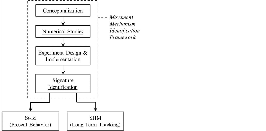
Figure 1. Movement mechanism identification general framework diagram.
1. Conceptualization: Estimation of the mechanism performance and timescale should be initially performed using visual inspection, review of existing documents, and heuristics.
2. Numerical Studies: To confirm or refute the initial assessment of movement timescale, numerical studies through scenario analysis should be performed.
3. Experiment Design & Implementation: Sensing technology appropriate for measuring the movements/deformations should be designed and installed based on the objectives of the study and mechanism timescale.
4. Signature Identification: The measured data should be processed and interpreted to identify the signature of the mechanism.
Once the movement mechanism has been adequately identified it can then be properly assessed based on the objectives of the study. One of the typical objectives is to evaluate the mechanism in its present state through model-experiment correlation (St-Id). Another objective may be to track the performance of the mechanism with time allowing for proactive maintenance (SHM). A recently completed study of a steel tied-arch bridge included the evaluation and monitoring of several movement systems (bearings, joints, and slotted connections). General information with regard to the structure and the portion of the research study related to evaluation of the movement mechanisms is discussed below.
3. Field Testing of a Tied-Arch Bridge
A numerical and field study was performed on a 168 m steel tied-arch bridge designed and constructed in 1929 (Figure 2). The primary structural system includes several chord members. An upper and middle chord is present which forms the arch itself. A lower chord is located at the bottom of the structure that is connected to the arch through vertical hangers. The intended flow of gravity loads place the vertical hangers under tension. These forces are transferred into the upper and middle chords of the arch putting them in compression. The spreading of the arch is then resisted through substantial tension of the lower chord.
Thermal loads develop in the structure as a result of the frictional force at the bearings (not including the effects of temperature gradients or material differences). A uniform temperature increase of the arch results in a restoring frictional force at the bearings. This places the lower chord in compression and the upper and middle chords are subjected to tension and compression, respectively (Figure 3). Of course for a uniform temperature decrease the opposite occurs.
In all cases, the superstructure loads are transferred to the foundations through the bearings and other connections. However, specific translational and rotational forces are released by these systems to prevent transfer from the superstructure to the substructure. The “expansion” end is located on the west side of the tied-arch. Origi-

Figure 2. Steel tied-arch bridge photo.

Figure 3. Load distribution due to a uniform temperature increase.
nally these bearings were a series of steel rockers, but were replaced in 2001 due to “locking” of the original components producing substantial build-up of forces at the east pier, resulting in cracking and other signs of distress. The replacement expansion bearings were a low profile friction-based assembly. The east end of the arch (“fixed” end) includes a unique movement mechanism. The last segment of the east end middle chord rigidly frames into the pier, however a slotted connection is present (Figure 4). This connection allows for longitudinal movement, but restrains all other translations and rotations. In addition, the last panel of the upper and lower chords, at the east end, frame together with a pin type connection which allows for in-plane rotation (also shown in Figure 4). All of these movement systems along the arch are critical for the long-term performance of the structure.
The research study performed on the arch bridge had many objectives which included individual assessment of the movement mechanisms due to their importance to the structure and therefore interest to the bridge owner. Discussion on the evaluation of two distinct arch movement mechanisms, with different timescales, is provided separately below. It should be mentioned the study also researched structural identification using a newly developed temperature-based method termed Temperature-Based Structural Identification (TBSI) [14] . The use of the temperature-based concept was also researched for development of a baseline for a global structural health monitoring system [15] .
3.1. Expansion Bearing Assessment (Long Period Mechanism)
The expansion bearings, described above, are termed high load disc bearings and are located at the west end of the arch (Figure 5). This is a friction based bearing system that has a Teflon member attached to the structure that sits on a stainless steel surface. The bearings are “guided” which means they allow longitudinal translation of the structure with all other degrees of freedom restrained.
As discussed earlier, the disc bearings were a replacement system due to breakdown of the original rocker bearings which induced substantial damage to the east pier through excessive build-up of thermal forces. As a result, periodic evaluation of the bearing system is of importance to the owner. The evaluation was conducted according to the guidelines described earlier. Therefore, an initial visual assessment of the bearings was conducted which indicated no signs of distress. With a friction-based system it was considered feasible that nonlinearity exists in the behavior of the bearings. The operating time scale was estimated as long period due to the scale of the structure.
Scenario analysis was performed to better understand the movement mechanism of the bearings prior to instrumentation. A numerical finite element model was utilized which was previously developed in a prior re-

Figure 4. Arch east end slotted and pin connection.
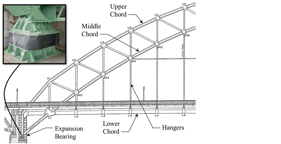
Figure 5. Steel tied-arch primary members with bearing inset photo (looking north).
search study [9] . Two primary scenarios were evaluated. The first was uniform temperature change of the structure and the resulting horizontal thermal forces/displacements at the bearings. The thermal force values were compared to an estimated static frictional resisting force with an assumed coefficient of friction. It was determined that a temperature change of roughly 10˚C was sufficient to “slip” the bearings. The normal temperature variation each day for this location is typically 15˚C. Therefore, it was considered likely that “slip” of the bearings occurred on a daily cycle. The second scenario evaluated was vehicular live load and the resulting horizontal forces at the bearings. It was clear that even for substantial live load the horizontal forces were nowhere near sufficient to “slip” the bearings. Analysis of these scenarios was important because it allowed for the reliable estimation of the bearing system timescale. For the arch bearings the mechanism is gradual and occurs over days because activation is as a result of global temperature variation.
The instrumentation selected to measure the bearing mechanism was vibrating wire (VW) displacement gages with an attached thermistor (Geokon, Model 44350) for direct measurement of the longitudinal movement and temperature variation. Figure 6 illustrates the location of the bearings and a photo inset of the instrumentation. In addition, VW strain gages with attached thermistors (Geokon, Model 4000) were selected for the middle chord members framing into the bearings to obtain the thermal forces (location show in Figure 6). VW technology was chosen due to its proven accuracy, repeatability, and stability with temperature-based measurements [16] . For complete details of the instrumentation design of the entire structure refer to Yarnold [15] .
A signature of the bearing movement mechanism was identified through measurement over one year with a sampling rate of once every three minutes. The bearing behavior in the short-term (days) can appear to be linear with a high bearing stiffness, when observing the temperature versus displacement response (Figure 7(a)). However, observing the response over a longer period indicates a bi-linear temperature versus displacement behavior (Figure 7(b)). Essentially, the short term (stiff and linear) support behavior is occurring when the bearing is restrained by static friction and only experiencing movement due to shear deformation of the bearing assembly. After sufficient force is generated to overcome the static friction a “slip” occurs and the structure is free to expand or contract. The stiffness during the “slip” period is that due to dynamic friction. The “stick-slip” longitudinal displacement mechanism is a cyclic behavior. This displacement mechanism has been observed throughout the year (Figure 7(c)).
The bearing displacement information was used along with the converted middle chord thermal forces (FMC) from the measured strains (shown in Figure 8) to calculate the current coefficient of friction of the bearings (μBRG). This was achieved by creating a free body diagram at the west end of the arch due to uniform temperature change, as shown Figure 9. From equilibrium the forces can be summed in the horizontal direction to find the frictional force of the bearing (FBRG). This is expressed in Equation (1), assuming negligible shear force in
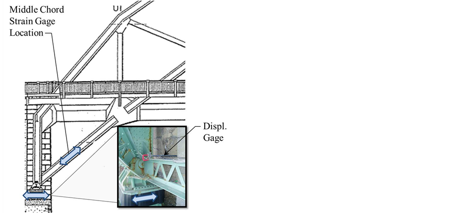
Figure 6. Arch west end bearing displacement and middle chord stain measurement locations.
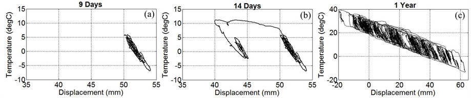
Figure 7. Temperature versus displacement relationship over (a) 9 days; (b) 14 days; and (c) 1 year.

Figure 8. Middle chord mechanical strain time history plot.
the vertical member (confirmed with the FE model). The resulting FBRG was equal to roughly 592 kN (133 kips) at each of the bearings.
 (1)
(1)
The coefficient of friction of the bearings (μBRG) was then obtained from Equation (2) where DLR is the dead load reaction at the bearing. This dead load reaction was obtained from the FE model and is roughly equal to 8007 kN (1800 kips). Therefore μBRG was calculated as approximately 0.07 for each of the bearings.
 (2)
(2)

Figure 9. Free body diagram at the west end bearing due to uniform temperature change.
The measured coefficients of friction (0.07) for each bearing were within the tolerances specified by the bearing manufacturer in 2001 (ranging from 0.045 to 0.10 based on the temperature). This confirmed adequate performance of the bearings in their present state and was reported to the bridge owner.
3.2. Slotted Connection (Short Period Mechanism)
As discussed earlier, a unique mechanism is present on the “fixed” end of the arch. The last segment of the east end middle chord frames into the pier that includes a slotted connection (Figure 4). The connection allows for longitudinal movement of the member, but restrains all other translations and rotations. This mechanism is intended to release the axial forces in the middle chord preventing transfer to the pier.
An initial visual assessment of the slotted connections provided minimal information with regard to the performance. The appearance was less than ideal due to the surface corrosion and rust staining. Due to this visual appearance the owner was contemplating rehabilitation of the slotted connections.
This connection type is also friction-based, but in this case it is steel-on-steel. The movement timescale was difficult to even estimate using only heuristics. Therefore, scenario analysis was performed to better understand the movement mechanism prior to instrumentation. The numerical finite element model was again utilized to evaluate the same scenarios (temperature change and vehicular live load). The first scenario, uniform temperature change of the structure, again indicated daily temperature loads were sufficient to “slip” the connections. However, for the slotted connection, the second scenario (live load) was also sufficient to “slip” the connections. This indicated the slotted connection has the potential to be active over a rapid timescale, but if sufficient live load is not present the connection could also be activated over longer periods from temperature change.
As a result of the combined drivers of the movement mechanism (thermal and live load forces) it was decided to obtain slow speed stable measurements through VW strain gages (Geokon, Model 4000) attached to the middle chord members which include the slotted connection. This decision was consciously made knowing characterization of the rapid behavior could not be obtained. However, the important information could be acquired which was the long-term build-up of forces, if any. Characterization of the rapid movement signature was considered utilizing electrical resistance strain measurement and/or displacement measurement across the connection, but was not selected due to additional cost and limited benefit. Acceleration measurement was also considered but not selected due to limited signal-to-noise, substantial data processing, data storage, and cost of the equipment.
A signature of the mechanism was identified through measurement over one year with a sampling rate of once every three minutes. The information obtained from the measurements indicated continual release of axial force with a maximum build-up of roughly 15 με. These results indicated the connections were functioning properly. The findings assured the owner the slotted connections were performing adequately delaying rehabilitation plans and using the financial resources for other pressing needs.
4. Conclusions
A general framework for identification of movement mechanisms was researched and implemented on an operating bridge. The framework begins with 1) conceptualization of the structure through visually assessment, document review, and heuristics. After a basic understanding of the mechanisms and the overall structure, 2) numerical studies are performed with the objective to confirm or refute the initial assessment of the movement timescales. This information is valuable for proper 3) experiment design and implementation. Appropriate sensing technology should be selected for measuring the movements/deformations while satisfying the objectives of the study. As a result, the data gathered from the field measurements can be processed and interpreted for 4) identification of the mechanism signature. An evaluation can then be performed for the present state of the mechanism and/or monitor the performance with time.
Identification of movement mechanisms on various structures, including those presented herein, has illustrated the following conclusions/recommendations:
• Visual appearance alone is inadequate for evaluation of movement systems.
• The operating timescale is crucial for proper measurement and identification of movement systems.
• There is no one correct type of instrumentation for characterization of a movement mechanism.
• Understanding what can and cannot be concluded from a particular sensing application is essential.
• Movement system functionality if critical for the long-term performance of the structure.
Acknowledgements
The author would like to thank the owner of the steel tied-arch bridge for their continued support throughout this project. The author would also like to acknowledge Jeffrey Weidner, Nathan Dubbs, John Prader, and Ehsan Minaie of Intelligent Infrastructure Systems along with Franklin Moon and A. Emin Aktan of Drexel University.
References
- FHWA (2012) National Bridge Inventory (NBI). FHWA, Washington DC.
- Mendez, V.M. (2012) 1st Letter Report of the TRB Long-Term Bridge Performance (LTBP) Committee, in Transportation Research Board. The National Academies, Onlinepubs.
- FHWA (2001) 23 CFR Part 650, in FHWA Docket No. FHWA-2001-8954. National Bridge Inspection Standards. FHWA, Washington DC.
- ASCE and SEI (2013) Structural Identification of Constructed Systems. In: Catbas, N., Kijewski-Correa, T. and Aktan, A.E., Eds., Approaches, Methods, and Technologies for Effective Practice of St-Id, 1-13
- Ni, Y., et al. (2007) Assessment of Bridge Expansion Joints Using Long-Term Displacement and Temperature Measurement. Journal of Performance of Constructed Facilities, 21, 143-151.http://dx.doi.org/10.1061/(ASCE)0887-3828(2007)21:2(143)
- Cao, Y., et al. (2011) Temperature Effects on Cable Stayed Bridge Using Health Monitoring System: A Case Study. Structural Health Monitoring, 10, 523-537. http://dx.doi.org/10.1177/1475921710388970
- Swanson, B., Malla, R. and Shaw, M. (2013) Laboratory Testing, Field Installation, and Monitoring of a Silicone Foam Sealant for Bridge Expansion Joints. Journal of Bridge Engineering, 18, 758-767.http://dx.doi.org/10.1061/(ASCE)BE.1943-5592.0000425
- Crocetti, R. and Edlund, B. (2003) Fatigue Performance of Modular Bridge Expansion Joints. Journal of Performance of Constructed Facilities, 17, 167-176. http://dx.doi.org/10.1061/(ASCE)0887-3828(2003)17:4(167)
- Yarnold, M.T., et al. (2012) Evaluation of a Long-Span Steel Tied Arch Bridge Using Temperature-Based Structural Identification. International Association for Bridge Management and Safety, Stresa.
- Chen, Q. (2008) Effects of Thermal Loads on Texas Steel Bridges. The University of Texas, Austin.
- Herman, R., et al. (2007) Performance of Steel Bridges under Thermally Induced Loads. World Steel Bridge Symposium, New Orleans, 5-7 December 2007, 1-8.
- Dubbs, N.C. (2012) Development, Validation, and Assessment of a Multiple Model Structural Identification Method. Drexel University, Philadelphia.
- McDonald, J., Heymsfield, E. and Avent, R. (2000) Slippage of Neoprene Bridge Bearings. Journal of Bridge Engineering, 5, 216-223. http://dx.doi.org/10.1061/(ASCE)1084-0702(2000)5:3(216)
- Yarnold, M.T., Moon, F.L. and Aktan, A.E. (2013) Temperature-Based Structural Identification of Long-Span Bridges. Submitted to Journal of Structural Engineering.
- Yarnold, M.T. (2013) Temperature-Based Structural Identification and Health Monitoring for Long-Span Bridges. Drexel University, Philadelphia.
- Zalt, A., et al. (2007) Evaluating Sensors for Bridge Health Monitoring. IEEE EIT, Chicago.