Engineering
Vol.4 No.12(2012), Article ID:25862,4 pages DOI:10.4236/eng.2012.412114
A Simple Detection System for Two Classical Sagnac Interferometer Configurations
Centro de Ciencias Aplicadas y Desarrollo Tecnológico, Universidad Nacional Autónoma de México, México
Email: eduardo.sandoval@ccadet.unam.mx
Received October 6, 2012; revised November 6, 2012; accepted November 15, 2012
Keywords: Sagnac Interferometer; Instrumentation; Photodetector; Data Acquisition
ABSTRACT
Two interferometric systems were built, one in bulk optics and other one in fiber optics for showing the instrumentation stage designed for these devices, supported in a photodetector. This stage has a circuit for amplification, analog filtering and software for single channel data acquisition and digital filtering. Based on the Sagnac effect in bulk optics and in fiber optics, the Sagnac interferometer has many applications, nevertheless the methods of construction, design and instrumentation for the sensors used on both types of interferometers are well-known, but very common or general form, for this reason this work approaches some of the methodologies for the design and construction of these devices, obtaining higher sensitivity and better contribution in its respective interferometric paths. We used the simplest design for each interferometer, proposing the best detection limit for each one; to obtain the previous thing, we implement the three previous steps: amplifiers and analogous filters, software for filtering the digital sign. The data acquisition method used to allow us to obtain faster results, using the card of a PC, getting real time measurements and digital processing of the signal.
1. Introduction
Considering the two well-known configurations of the Sagnac interferometer, in bulk and fiber optics, we know that both have been carried out in multiple researches to be able to determine their maximum theoretical and practical sensibility, but the interferometer in bulk optics has been less studied than the interferometer in fiber optics; this is because according to the principle proposed by Sagnac in the XX century [1,2], it was limited just to a theoretical study but the technology to develop this interferometer came later, until the masers [3,4] and lasers appeared [5-7]. After the existence of the first lasers, the development of the Sagnac interferometer in bulk optics was very limited and therefore just applicable as a system of academic demonstration [8]. The loop used, had big dimensions and very poor sensibility, for this, was necessary a great amplification with low efficiency in that time [9], but it was still very difficult to use as an efficient sensor of angular movements [10].
In the 70’s the fiber optic was well developed and by using this channel of propagation the advantages in the Sagnac interferometer grew, in this way the development of the first Sagnac interferometer in fiber optic lead the Sagnac interferometer in bulk optics relegated and to a certain point forgotten or employed as the theoretical model in general, of the fiber optic gyroscope [11]. After that, the Sagnac interferometer in fiber optic was studied thoroughly, suffering some modifications and improvements until our days [12,13].
There’s much written about the importance of the physical effect or the physical improvements in the Sagnac interferometer in fiber optics for new applications, and in the most of them they use advanced opto-electronic detection systems to work with interferometers [14-16].
The improvement made in our case was to optimize an electronic circuit used for the light detection in both types of interferometers depending on the correct implementation of the Sagnac interferometer and the detector used [17].
Part of the objective of this work, is to show the implementation of the opto-electronic sensor system designed with the appropriate instrumentation to achieve good sensed signals of the Sagnac interferometer in bulk optics and in fiber optic by sensing the light intensity at the output of the interferometer, showing the basic principles of sensing, optical detection, opto-electronic transduction and finally the signal processing.
2. Theoretical Bases of the Sagnac Effect
The Sagnac effect was studied and demonstrated in 1913 by the French George Sagnac. The physical principle is explained as a light beam of a coherent source, which is injected to a beam splitter that divide the beam in two beams with the same wavelength and amplitude; then the beams travel in a closed loop formed by a optical path of mirrors and then make a recombination of the beams in the same point where they were divided. The two paths form a closed trajectory, which contains an area that dependents of the optic path, also the beams travel in opposite directions in the optical path formed by the mirrors. Therefore the path that each beam follows is the same one but in opposite direction and finish in the same point where they were divided [1]. In the Figure 1, the scheme proposed by Sagnac is observed to demonstrate the physical phenomenon.
The beams phase difference of the in counter-propagation in the Sagnac interferometer is given by:
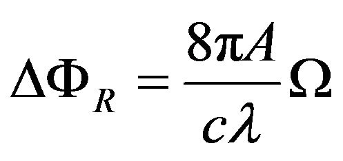 (1)
(1)
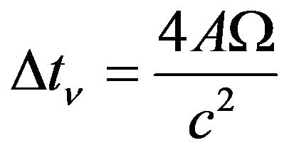
The arrival time difference of the beam splitter, for the beams in the Sagnac interferometer is given by:
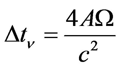 (2)
(2)
where:
λ - is the wavelength of the light beams.
W - is the angular velocity of the system.
c - is the speed of the light in the air.
A - is the area enclosed by the optical path.
π - is a constant.
The demonstration of the interferometer in bulk optics is valid and applicable to the fiber optic interferometer.
The analysis is the same one, but the area enclosed by the light beams in counter-propagation is multiplied by the number of turns contained in the coil of fiber optics; then the equations of the Sagnac interferometer in fiber optics are:
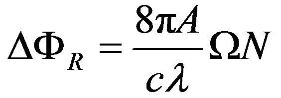 (3)
(3)
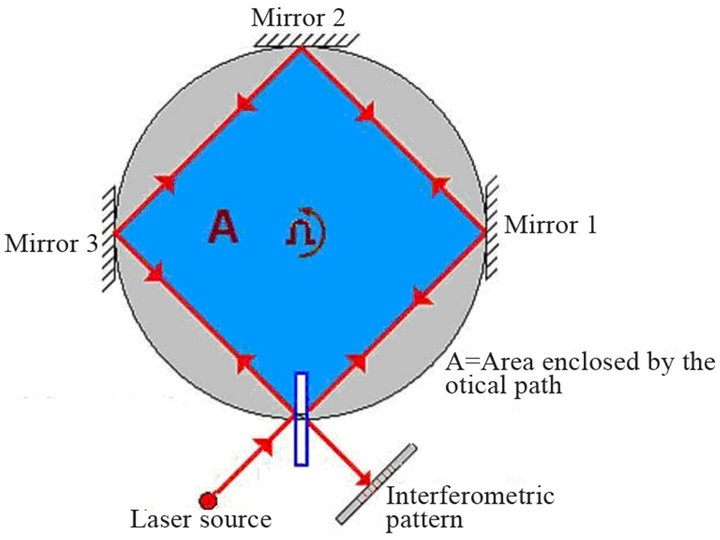
Figure 1. The classic model of Sagnac’s interferometer.
 (4)
(4)
where:
λ - wavelength of the light beams.
W - angular velocity of the system.
c - speed of the light in the air.
A - area enclosed by the optical path.
π - is a constant.
N - number of turns of the fiber optic coil.
This way the sibility given by the interferometer in fiber optic depends more on the number of turns, growing N times this sensibility. Nevertheless many other factors intefere to be able to have a greater sensibility in the fiber optic interferometer [18]. The research of high sensibility in the case of the fiber optics interferometer has been made for many years [19].
The base theory of the Sagnac effect is the same one for both interferometer; but the advantages that the fiber optics interferometer offers are greater than the ones of bulk optics interferometer [15].
3. Implementation Work
The main objective of this work resides in demonstrating the reaches in sensibility of the Sagnac interferometer in bulk optics and in fiber optics, based in the new electronic devices to carry out a good instrumentation for both systems. Both interferometers were implemented in their simplest configuration to work with the actual signal processing system and obtain a higher sensibility.
Although both interferometers can be built according to the basic principle, the interferometer employed in bulk optics was modified of its traditional configuration, because with these changes a remarkable increment in its sensibility is achieved. Knowing that the system don’t depend on the optical path that beams follow in counterpropagation, but it depends of the area that contains; a modification that help in the appropriate distribution of the elements of the system was made [20].
The second modification is based on the sensibility given by the system that depends strongly on the optical detection stage and its transduction, based on the change of the interferometric pattern to reach the limits of detection [17]. It is possible to achieve a Sagnac interferometric system with high sensibility compared with the traditional interferometric system. This interferometer reaches the maximum limit of detection due to the number of interference lines that can be used for sensing. The scheme of the Sagnac interferometer in bulk optic for this work is shown in the Figure 2.
The interferometer in fiber optic was carried out in the minimal configuration, Figure 3. In this work we worked with a low power infrared laser diode with a wavelength of 980 nm, and we used a photodetector that we already
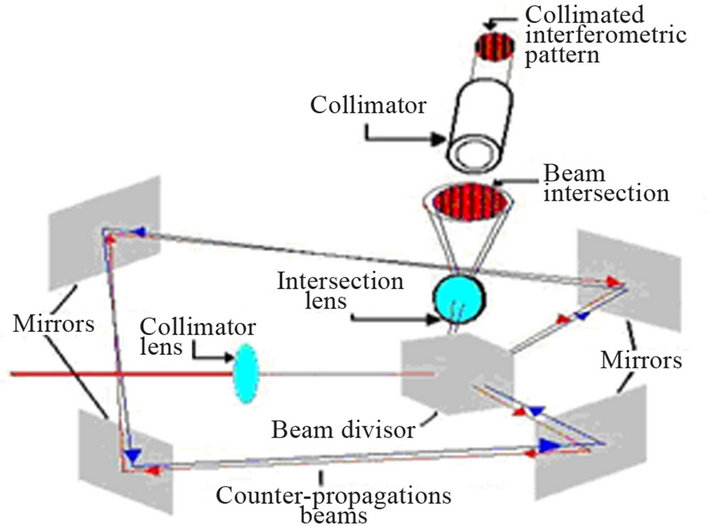
Figure 2. The model proposed and implemented of Sagnac’s interferometer in bulk optics.

Figure 3. Minimal configuration of the interferometer in fiber optics.
had, and by consulting the curves that the manufacturer’s datasheet provides for the Thorlabs FGA21. Here, is important to remember that the photodetector has two operation modes: the photovoltaic mode which implies to work in the non-linear region; and the other operation mode is the photoconductive, and this is the one of our interests because this is in the linear region of the voltage-current curve.
After this we make some tests to determine by varying the current of the laser diode and fixing this value at the middle point of the complete detection range of the photodetector (in our case was supplying 45.4 mA which produces 3.61 mW), this because; for using the Sagnac interferometer as an angular movement sensor we need to sense when the rotation is in one direction or in the opposite that means above or below this middle point.
Then, during photoconductive operation, a reverse bias on the photodiode results in a number of response advantages, such as a faster rise time. One inconvenience is that the dark current increases with this applied to bias current, so noise is introduced into the system, and we need a filter to cancel it.
But before amplifying or filtering the signal of the transducer we need a coupling stage to maintain the signal, and prevent attenuation due to a bad coupling.
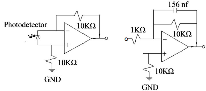
The sensed signal given by the Sagnac interferometer is based on the change in the power of optical interfereence, because of that, the transducer outputs a DC current and then we used the following configuration in Figure 4(a), we see the circuit diagram of the coupling did by the amplifier which also converts the current produced on the detection device to voltage. After this stage goes the filtering which was necessary because the need of avoiding the noise and due to the low frequency of the changes it’s a low pass filter with a cut frequency of 100 Hz, Fgure 4(b).
The most of the existent opto-sensing systems have more stages of processing after the coupling and pre-amplification, Figure 4(c); these other stages are mainly for amplification and filtering and can be carried out in a very simple way taking some very important considerations for the optimum performance of the system.
The Sagnac interferometer can be mainly employed as angular movement sensor, but its applications in other areas like sensor of other physical variables or magnitudes make it very attractive [21,22]. Depending of the application of the interferometer is necessary to change the range of sensing. For using it as an angular movement sensor, it is necessary to know the speed of the movement to know the filtering needed according to these speeds.
Another problem to solve when designing this coupling is the offset presented by the pre-amplifier; this can be removed easily in the stage of pre-amplification. By removing this offset we could adjust the sensed signal to zero when the interferometer is in steady state. The offset can be eliminated in two ways, one with a voltage splitter and the other with capacitors; the best method is the em-
 (a)
(a)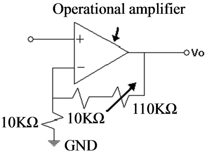 (b)
(b)
Figure 4. (a) Current to voltage converter; (b) Active filtering stage; (c) Amplifying stage.
ployment of capacitors. At this stage, is necessary the use of tantalium capacitors or ceramic ones, because the polarized capacitors force us to use a phase modulator in the circuit of the interferometer to detect the direction of the movement; in this process, and without polarized capacitors and due to the proposed instrumentation it is possible to continue without this phase modulator. With these considerations and the possibility of using commercial amplifiers and tantalium capacitors we avoid signal loss due to coupling between the stages, and the output signal is easy to manipulate from this point.
The obtained signal has enough amplitude to be measured with a multimeter or an oscilloscope. The amplitude range of this signal goes from 0 - 5 Vpp. Using the mic input of a personal computer; it is possible to process it in real time. This is because the sound acquisition card of the PC counts with a filter stage for signals in a frequency range between 20 and 20 kHz, and an analogdigital converter of 16 bits, also to be considered the sampling time to determine the best option in the acquisition. Using a simple application in Labview for acquisition and signal process is possible to carry out the sensed signal and visualization in real time. This way is possible to avoid the analog filters and makes possible a digital filtration, selecting the adequate filter range and adaptable to the response needed, also is possible to save the measures and use them again or longer time measurements.
4. Conclusion
An efficient use of instrumentation systems for signal acquisition is vital for the process of measuring a signal. But when it is not possible to use high-tech instrumentation devices, we can use high efficiency electronic circuit designs of low cost, always considering the ranges of the involved signal to detect, this is the objective of the shown work. Using the sound acquisition card of a computer is possible to use it for data acquisition with LabView, with a simple program and information about our sound acquisition card like the sampling rate, is possible to carry out a digital signal process in real time. This is useful for small signal detection and it also works for different type of physic variables; But in this work it was used with the Sagnac interferometer in bulk optics and fiber optic for the simplicity of the models and the trouble in these devices to take out a measurable signal. One of the advantages that was presented in this work is a device without a phase modulator in the fiber optic nucleus to determine the movement direction of the system, this is because we considered that the changes of intensity were in the linear part and in the detection range of the photodetector and that allowed us to detect the changes in the signal directly in the intensity without using additional equipment.
5. Acknowledgements
The authors acknowledge support from the UNAMDGAPA (PAPIIT-IT101712).
REFERENCES
- G. Sagnac, “L’éther lumineux démontré par l´effet du vent relatif d´éther dans un interféromètre en rotation uniforme,” Comptes rendus de l´Académie des Sciences, Vol. 95, 1913, pp. 708-710.
- G. Sagnac, “Sur la prevue de la réalité de l’éther lumineux par l’expérience de l’interférographe tournant,” Comptes rendus de l´Académie des Sciences, Vol. 95, 1913, pp. 1410-1413.
- A. H. Rosenthal, “Regenerative Circulatory MultipleBeam Interferometry for the Study of Light-Propagation Effects,” Journal of the Optical Society of America, Vol. 52, No. 10, 1962, pp. 1143-1148. doi:10.1364/JOSA.52.001143
- C. V. Heer, “Optical Maser Photon Rate Gyroscope,” 1964 Symposium on Unconventional Inertial Sensors, Long Island, 19-20 October 1964.
- W. M. Macek and D. T. M. Davis Jr., “Rotation Rate Sensing with Traveling-Wave Ring Lasers,” Applied Physics Letters, Vol. 2, No. 3, 1963, pp. 67-68. doi:10.1063/1.1753778
- P. K. Cheo and C. V. Heer, “Beat Frequency between Two Traveling Waves in a Fabry-Perot Square Cavity,” Applied Optics, Vol. 3, No. 6, 1964, pp. 788-789. doi:10.1364/AO.3.000788
- C. V. Heer, “Resonant Frequencies of an Electromagnetic Cavity in an Accelerated System of Reference,” Physical Review, Vol. 134, No. 4A, 1964, pp. A799-A804. doi:10.1103/PhysRev.134.A799
- G. B. Malykin, “Earlier Studies of the Sagnac Effect,” physics Uspekhi, Vol. 40, No. 3, 1997, p. 317. doi:10.1070/PU1997v040n03ABEH000218
- T. J. Hutchings, et al., “Amplitude and Frequency Characteristics of a Ring Laser,” Physical Review, Vol. 152, No. 1, 1966, pp. 467-473. doi:10.1103/PhysRev.152.467
- J. M. Catherin and B. Dessus, “Traveling-Wave Laser Gyrocompass,” IEEE Journal of Quantum Electronics, Vol. QE-3, No. 11, 1967, pp. 449-453. doi:10.1109/JQE.1967.1074408
- V. Vali and R. W. Shorthill, “Fiber Ring Interferometer,” Applied Optics, Vol. 15, No. 5, 1976, pp. 1099-1100. doi:10.1364/AO.15.001099
- O. Pottiez, et al., “Easily Adjustable, Power-Symmetric Nonlinear Optical Loop Mirror for Ultrafast Photonic Applications,” Symposium IEEE/LEOS Benelux Chapter, Ghent, 2004.
- S. W. Lloyd, et al., “Measurement of Reduced Backscattering Noise in Laser-Driven Fiber Optic Gyroscopes,” Optics Letters, Vol. 35, No. 2, 2010, pp. 121-123. doi:10.1364/OL.35.000121
- C. Zhang, et al., “Thermal Analysis of the Effects of Thermally Induced Nonreciprocity in Fiber Optic Gyroscope Sensing Coils,” Optik, Vol. 122, No. 1, 2011, pp. 20-23. doi:10.1016/j.ijleo.2009.10.004
- B. Culshaw, “The Optical Fibre Sagnac Interferometer: An Overview of Its Principles and Applications,” Measurement Science and Technology, Vol. 17, No. 1, 2006, pp. R1-R17. doi:10.1088/0957-0233/17/1/R01
- L. R. Jaroszewicz, “Fiber-Optic Sagnac Interferometer as Real Sensor of the Physical Quantities,” Proceedings of the Symposium on Photonics Technologies for 7th Framework Program, Wroclaw, 12-14 October 2006, pp. 99-102.
- S. Palma-Vargas, G. E. Sandoval-Romero and A. Ramirez-Ibarra, “Detection Limit of a Sagnac’s Interferometer,” SPIE Proceedings of Sixth Symposium Optics in Industry, Monterrey, 8-9 March 2007. doi:10.1117/12.742278
- G. E. Sandoval-Romero, “Fiber Optic Gyrocompass Superluminescent Fiber Source,” IEEE A&E Magazine, 2005, pp. 19-20. doi:10.1109/MAES.2005.1499247
- M. Komachiya, H. Sonobe, S. Oho, K. Ohbu, T. Yuhara and H. Iizuka, “Secondary-Phase-Modulation Method for Open-Loop Fiber-Optic Gyroscopes,” Applied Optics, Vol. 35, No. 19, 1996, pp. 3719-3725. doi:10.1364/AO.35.003719
- S. Palma-Vargas, G. E. Sandoval-Romero and A. Ramirez-Ibarra, “Optical Angular Movement Sensor,” SPIE Proceedings of Photonics North, Québec, 5-8 June 2006, p. 634329. doi:10.1117/12.707966
- L. R. Jaroszewicz and Z. Krajewski, “Application of the Fibre-Optic Rotational Seismometer in Investigation of the Seismic Rotational Waves,” Opto-Electronics Review, Vol. 16, No. 3, 2008, pp. 314-320. doi:10.2478/s11772-008-0015-2
- G. Bertocchi, et al., “Single-Photon Sagnac Interferometer,” Journal of Physics B: Atomic, Molecular and Optical Physics, Vol. 39, No. 5, 2006, pp. 1011-1016. doi:10.1088/0953-4075/39/5/001