Engineering
Vol. 3 No. 7 (2011) , Article ID: 6150 , 7 pages DOI:10.4236/eng.2011.37088
Development of Roller Ends Forced-Contact Model and Cambering Technology for UCM Temper Mill (I)*
1School of Mechanical Engineering, State Key Laboratory of Metastable Materials Science and Technology, Yanshan University, Qinhuang Island, China
2Thin Strip Co., Ltd., Baoshan Iron & Steel Co., Ltd., Shanghai, China
E-mail: bai_zhenhua@yahoo.com.cn, {sihongxin, xiaodong_shi}@126.com
Received April 18, 2011; revised May 18, 2011; accepted May 25, 2011
Keywords: UCM, Temper Mill, Forced-Contact, Roll Shape, Roll Consumption
ABSTRACT
Roller ends forced-contact and overmuch roll consumption are the widespread problems in temper rolling process of thin strip for two-stand UCM temper mill. Fully thinking the equipment and technology characteristics of UCM temper mill, we took the newly-built 1220 UCM temper mill of Baosteel as the research object in this paper. A model of roller ends forced-contact and a calculation model of flatness for UCM temper mill are established after a great deal of site tracing and theoretical researches. On this basis, an optimal mathematical model of roll shape which is suited for UCM temper mill is developed. Working roll curve is the combination of cosine curve and high order curve. The cosine subentry is used to control edge wave, the high order curve subentry is used to control roller ends forced-contact. Furthermore, the chamfering curve of middle roller end is optimized. Those are the innovations. Through the above-mentioned technology, pressure distribution between rollers caused by the shift of middle roll becomes more homoge-neous, pressure peak disappeared, working life of roll is improved effectively as well. Relevant technologies have been used to the practice of 1220 UCM temper mill of Baosteel and have achieved good use effects, which is of further extending application value [1].
1. Introduction
Cold rolled thin strip production developed rapidly with the huge demand in household appliances, automobile, electronic, can-manufacturing in recent years. Temper rolling is the process nearest to finished product, it plays a vital role to the shape and mechanical property of rolled strip. In addition, it is found in practice that the contact of working rolls outside the plate width will appear when thin and narrow strip are temper rolled. The forced-contact of working roller ends will lead to that only partial presetting rolling force are used to make the metal deformed and the rest cause the roller ends squashed which will lead to the actual elongation is smaller than design value. And the product performance will not meet the users’ demand. Moreover, after the forced-contact of working roller ends happened, the rolling force consumed in the flattening of roller ends also increased with the increase of presetting rolling force. The increased rolling force will waste in the forcedcontact of working roller ends mostly when the rolling force increases to the certain extent. So that the increase of rolling force not only failed to increase elongation, but will shorten the rollers’ lifespan. Particularly, if the original shape model is still used, strip shape will not reach the target and even bring new shape defects.
Formerly, the cambering of four high cold mill in production site only aimed to a single wave, for examplewhen there are many edge waves, the convex roll-shape of working roll and backup roll is often adopted; when there are many center waves, the disposition form of roll configuration curves is the concave roll-shape of working roll and plain roll-shape of backup roll. These above disposition forms of roll configuration curves often can’t do anything about complex waves, even will lead to new wave defects. So, how to calculate the forced-contact value and relevant shape value accurately in the process of temper rolling and provide a relevant compensation technique is the emphasis of field tackling key problems. Therefore, a model of roller ends forced-contact and a computational model of flatness which is suited for UCM temper mill is established after lots of field tracing and theoretical research. Moreover, on the basis of this, starting with the roll crown optimization of working rolls and intermediate rolls, strip shape, roll consumption and the management of roll forced-contact are considered as well. A mathematical model of roll crown optimization which is suited for the working rolls and intermediate rolls of UCM temper mill is developed. Relevant technologies have been used to the practice of 1220 UCM temper mill of Baosteel and have achieved good use effects, which is of further extending application value.
2. The Model of Roller Ends Forced-Contact and Shape Calculation for the Process of UCM Temper Rolling
2.1. Introduction of Roller Ends Forced-Contact
What is called the forced-contact of roller ends is refer to the phenomenon that the contact of working rolls outside the plate width when paper-thin strip is temper rolled. As shown in Figure 1.
2.2. Establishment of the Model of Forced-Contact Value, Contact Width, Rolling Force and Shape of UCM Temper Mill
What can know after analysis is the model of mental deformation within the plate width still holds true even though the forced-contact of roller ends exists. Based on relevant model, the function of forward and backward tension ( and
and ) can be shown as follows:
 (1)
(1)
 (2)
(2)
where  is the transverse distribution value of strip thickness in exit,
  is the transverse distribution value of strip thickness in entry,
  is the transverse distribution value of length and used to express the incoming
Figure 1. The Schematic diagram of the forced-contact of roller ends.
profile, B is the width of strip,  is the average backward tension,
  is the average forward tension.
What is different is an additional pressure stress should be applied to the section of working roll which is outside the plate width in the load-carrying model of roller system if the forced-contact of roller ends is considered. As shown in Figure 2.
The model for elastic deformation of rolls still adopt the section dispersed way when the forced-contact of roller ends is considered, as shown in Figure 2. Assuming that the rolling force along the axis of roller is , the pressure between intermediate roll and working roll is
 , the pressure between intermediate roll and back-up roll is
 , ,the contacting pressure between working roll and working roll is
 . Assuming that the face length of working roll is
  and be divided into N sections (N is odd), the number of sections correspond to working roll’s left is NL, and the length of each section is
 . In order to analyze conveniently, the pressure between rolls are expressed with
 ,
,  ,
,  ,
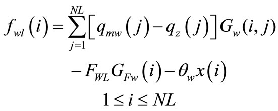
,  respectively. The bending deflection equation for the left and right sides of working roll can be expressed as follows [2]:
 (3)
(3)
 (4)
(4)
where  is the bending force acting on the left and right sides of working roll,
  is the pressure of i point between intermediate roll and working roll,
  is the rolling force of i point,
  is the contacting
Figure 2. The Schematic diagram of force analysis of roller system when consider the forced-contact of roller ends.
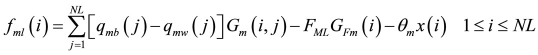
pressure of i point between working roll and working roll,  is the rigid corner of working roll which is relative to the rigid corner of back-up roll, NL is the number of sections which are correspond to the left part of working roll’s medium line.
  is the influence coefficient that the load of j section to the deflection of working roll’s i section, it is the function of
 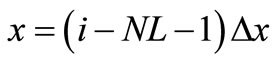 and
and :
:
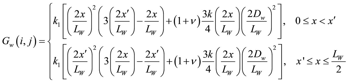 (5)
(5)
where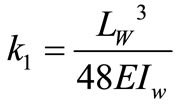 ,
,  ,
,  ,
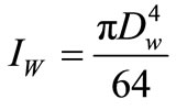
,  is the face length of working roll;
  is the influence coefficient that the bending load
  to the deflection of working roll’s i section, the expression of
  as follows:
 (6)
(6)
where  is the length of from working roll’s one end to the center line (the length of actuating arm) To the
 ,
,  , but to the
 ,
, .
.
In addition, the bending deflection equation along the vertical direction of intermediate roll is Left side:
 (7)
(7)
Right side:
 (8)
(8)
where  is the bending force acting on the left and right sides of intermediate roll;
  the pressure between intermediate roll and back-up roll;
  is the rigid corner of intermediate roll;
  is the influence coefficient that the load of j section to the deflection of intermediate roll’s i section,
  is the influence coefficient that the bending load of intermediate roll to the deflection of intermediate roll’s i section.
Here, the expressions of  and
and  approximate to the expressions of
  and
and . So, the expressions of
  and
and  can be obtained through the replacement of intermediate roller’s parameters and working roller’s parameters [3].
So, the bending deflection equation along the vertical direction of back-up roll is:
Left side:
 (9)
(9)
Right side:
 (10)
(10)
where  is the support force acting on the left and right sides of back-up roll;
  is the influence coefficient that the load of j section to the deflection of back-up roll’s i section;
  is the influence coefficient that the support force to the deflection of back-up roll’s i section Here,
  and
and  approximate to the expressions of
  and
and , So, they can be obtained through the replacement of back-up roller’s parameters and working roller’s parameters.
The deformation compatibility equation of working roll and intermediate roll:
 (11)
(11)
where ,
,  ,
,  is flattening coefficient between working roll and intermediate roll, and its expression is:
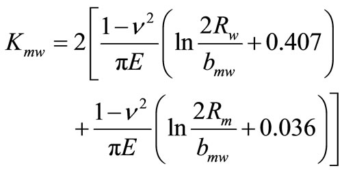 (12)
(12)
where  is half the contacting width of intermediate roll and working roll, and its expression can be obtained from Hertz formula:
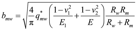 (13)
(13)
where  is contacting pressure per unit of face length between intermediate roll and working roll,
  are the poisson’s ratio of working roll and intermediate roll,
  are young modulus of working roll and intermediate roll,
  are radius of working roll and intermediate roll.
Considering that the material of working roll and intermediate roll is same, so the above formula can be written as follows:
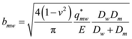 (14)
(14)
The deformation compatibility equation of intermediate roll and back-up roll:
 (15)
(15)
where  is the flattening coefficient between intermediate roll and back-up roll, its expression approximate to the expression of
  and can be obtained through the replacement of
  and
and ,
,  and
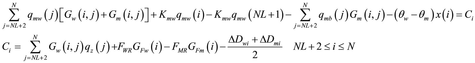
and . Substituting each deflection and flattening coefficient into the two above deformation compatibility equation. For the deformation compatibility equation of working roll and intermediate roll:
Left side:
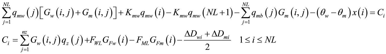 (16)
(16)
Right side:
 (17)
(17)
For the deformation compatibility equations of intermediate roll and back-up roll:
Left side:
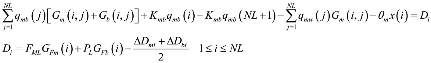 (18)
(18)
Right side:
 (19)
(19)
And then, the number of unknown number is  in the above system of equations, but the number of equations is
  in the above system of equations, there are lack of two equations of force equilibrium and two equations of momental equilibrium.
The equations of force equilibrium as follows:
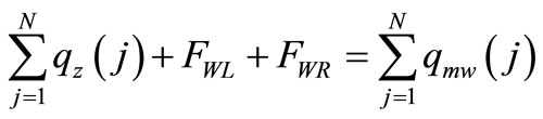 (20)
(20)
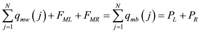 (21)
(21)
The equation of momental equilibrium for working rolls as follows:
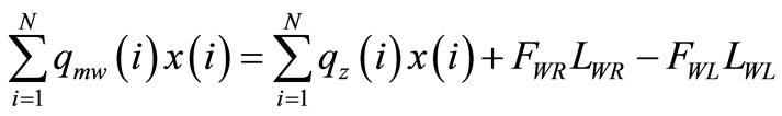 (22)
(22)
The equation of momental equilibrium for back-up rolls as follows:
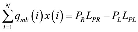 (23)
(23)
And then, both the number of unknown number and the number of equations are , so, the solutions can be obtained.
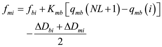
The deflection of working roll can be computed after getting the above solutions, and then  can be computed as well based on the following formulas:
 (24)
(24)
where  is the flattening coefficient between working roll and rolled piece , and its expression is [4]:
 (25)
(25)
Here, 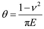 ,
,  is absolute gauge reduction,
 is the force that acts on per unit of face length.
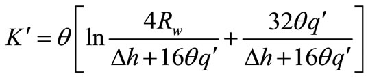
  is the flattening coefficient between working roll and working roll, its expression is similar to the expression of
 .
.
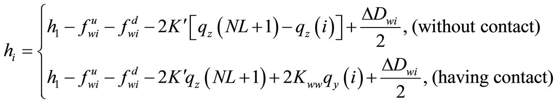
It should be noted that  is the concept of roll gap broadly. Within the width of strip,
  represents the gauge distribution of strip in exit; but in the section of roll’s contact,
  is a negative and its absolute value represents the level of roll’s forced-contact; outside the width of strip represents apparent roll gap.
Then, based on the above analysis, the following formula existed:
 (26)
(26)
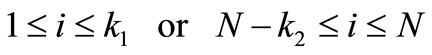
Obviously, if  existed from k point, which means the forced-contact between rolls appeared from k point. Assuming that the number of
  is
is  on the left, and the number of
  is
is  on the right, the width of roll’s forced-contact is
 ,
,  satisfy the following formula:
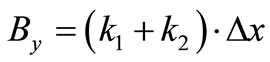 (27)
(27)
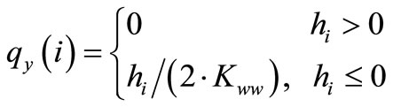
 , the amount of roll’s forced-contact can be expressed with the following formula:
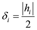 (28)
(28)
Now,  , the actual rolling force is:
 (29)
(29)
Last, coupling (1) to (29),  the strip shape;
  width of roll’s forced-contact;
  the amount of roll ends’ forced-contact and
  the actual rolling force all can be obtained.
2.3. The Field Test of the Model of Roller Ends Forced-Contact and the Computational Model of Flatness for UCM Temper Mill
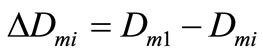
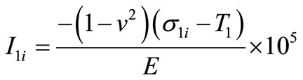
In order to verify the correctness of relevant models introduced in 2.2, the second stand of 1220 UCM temper mill of Baosteel was taken as research object particularly. The working roll, intermediate roll and back-up roll were all flat roll. 0.15 × 718 mm was chosen as specimen to do the forced-contact test (related equipments and process parameters as shown in the following Table 1). The value of contact width, actual rolling force and strip shape were given though test and also computed through the models at the same time. (It should be noted that the cutting method was adopted for the temper mill don’t have shape meter.) And then, error analysis was proceeded through the comparison of test value and computed value, the results of error analysis are shown in the following Table 2. After the forced-contact test, the production of this specification proceeded with the elongation of 1.0% until roll changing. The length of rolling this moment was recorded in the following Table 2 as well. It should be noted that the way to compute flatness errors is the following Equation (30). The following Equations (31) and (32) are used to compute the maximum of computed shape value and actual shape value.
 (30)
(30)
 (31)
(31)
 (32)
(32)
where  is the flatness errors,
  is the actual shape

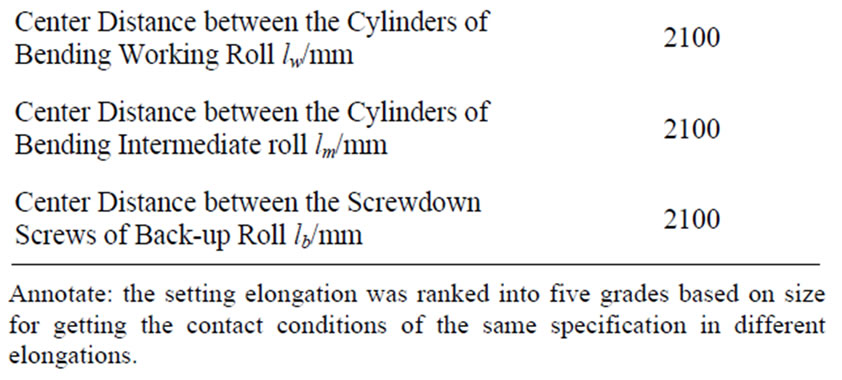
Table 1. Equipments and process parameters of forcedcontact test.
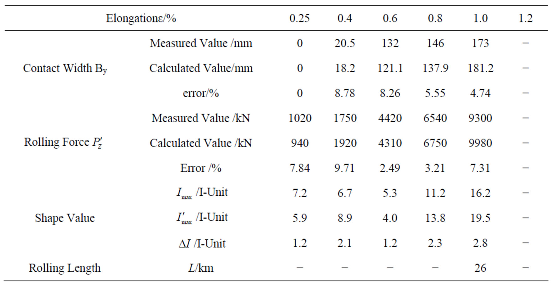
Table 2. Comparison between test results and computed results.
value,  is the computed shape value,
 (where E and
  are the young modulus and poisson’s ratio respectively).
  is the maximum of actual shape value
  is the maximum of computed shape value.
First of all, it can be seen through Table 2 that there isn’t roller ends’ forced-contact when the elongation is 0.25% (the contact width is zero); and the roller ends’ forced-contact begin to appear when the elongation is increased to 0.4%; later on, with the increase of elongation, the roller ends’ forced-contact become worse and worse; when the elongation increased to 1.11%, the rolling force reach to the limit value 12000KN of temper mill and the elongation will not reach to 1.2%.
In addition, it also can be seen clearly through Table 2 that the error is within 10% compared with test results when the model of Section 2.2 is adopted, and the error of shape value is within 3I. So, the model can fully satisfy the precision request in the engineering application.
3. REFERENCES
- Z. H. Bai, “Development and Research of Shape Control Technology about Skin Mill,” Doctoral Dissertations, Yanshan University, Qinhuang Island, 2002.
- J. C. Lian and H. M. Liu, “Guage and Shape Control,” Weapon Industry Press, Beijing, 1995.
- Z. H. Bai, X. P. Kang and R. B. Long, “Practical Temper Rolling Force Model and Its Self Study Technology,” Steel, Vol. 43, No. 10, 2008, pp. 51-54.
- Z. H. Bai, Y. F. Jiang and X. D. Li, “Kiss between Roller Ends in Skin Rolling Process of Super Thin Strip,” Chinese Journal of Mechanical Engineering, Vol. 42, No. 8, 2006, pp. 224-228. doi:10.3901/JME.2006.08.224
NOTES
*Contract/grant sponsor and Grant Number: 1) Hundred Excellent Researchers Award Program of Department of Education of Hebei Province (CPRC018); 2) Natural Science Foundation of Hebei Province (Surface Project) (E2011203019); 3) Natural Science Foundation of Hebei Province (Base Special Fund) (08B015).