Engineering
Vol. 3 No. 9 (2011) , Article ID: 7333 , 7 pages DOI:10.4236/eng.2011.39114
The P40 Cutting Tool Wear Modelization Machining Fk20MnCr5
Laboratoire d’Ingénierie des Transports et Environnement, Campus Châab Ersas, Université Mentouri Constantine, Constantine, Algerie
E-mail: idrissamara@gmail.com
Received March 23, 2011; revised April 25, 2011; accepted May 10, 2011
Keywords: Machining, Wear, Cutting Tools, Dry Lathing
ABSTRACT
This work presents an experimental study to describe a wear zone in the P40 cutting tools used during a dry lathing. Mechanics of cutting has been presented to investigate the effects of edge geometry of the cutting tool carbide cutting insert. In the field of the metals cutting, the wear of the cutting tools leads to a degradation of the cutting zone and work. It is thus important to study the evolution of the cutting criteria allowing to follow the tool degradation during a manufacturing operations and thus to decide whether to replace the tool or not. Three parameters: cutting speed, cutting feed and cutting depth are considered to modelize the tool wear. An experimental device, particularly, a work-piece in Fk20MnCr5 material was cutted on a conventional lath for shaping, a high resolution sensor (HRS), had been used for measuring wear zone. The relationship between “the cutting speed, the depth of cut, the feed rate” are analysed and modelled. In order to deduce this shape the spline method to modelize the wear zone has been used and a mathematical model has been proposed.
1. Introduction
The designs of cutting tool geometry and its influence on machining performance have been a research topic in metal cutting for a long time. In dry cutting operations, the friction and adhesion between chip and tool tend to be higher, which causes higher temperatures, higher wear rates and, consequently, shorter tool lives [1].
According to the research reports concerning cutting tool wear, it can be said that measure factors which affect the generation of a crater wear of a carbide cutting tool at higher cutting speed is mutual diffusion between both components of work and cutting tool materials under high temperature and high pressure [2].
Carbide cutting inserts are used extensively in metal cutting. The economical benefits of using carbide cutting inserts can be offset by rapid tool wear or premature tool failure if they are not used properly. Flank wear is a major form of tool wear in metal cutting [3].
Some work on tool wear focused on prediction of tool wear by empirical modeling methods [4], time series methods [5], frequency domain analysis [6], pattern recognition and statistical methods [7], and hidden markov model method [8] for tool wear monitoring. These studies have gained various degrees of success in tool wear modeling although lots of experimental data are needed [3].
The effect of edge preparation on the mechanics of cutting has been investigated by many researchers by using various methods such as analytical, computational, and experimental methods [9].
In order to involve all the technological operations, optimum technological processes, optimum tool selection, suitable combination of tool-work-piece material and determination of optimum cutting variables and tool geometry must be considered [10].
In dry cutting operations, the friction and adhesion between chip and tool tend to be higher, which causes higher temperatures, higher wear rates and, consequently, shorter tool lives. According to K. Bouacha et al., [11], during material cutting, complex and mutual interactions are created between tool and work-piece at the contact surface.
Consequently, significant forces and high temperatures are recorded causing wear and sometimes breakage of the tool. As a result, the precisions on the finished work-piece dimensions as so as the surface roughness are altered or the material mechanical characteristics are modified [12]. The metals cut phenomenon showed when a tool penetrates in a metal part to form a chip, the material located close to surface is strongly sheared.
The deformation is carried out at very high speeds. The temperatures and stresses at the interface level are considerably high and lead to complex physicochemical phenomena. From that we can say that the cut of metals is a strongly coupled thermomechanical process in which plastic deforma-tions, the heat and the friction phenomena play a critical role in term of wear [13].
2. Experimental Study
Generally, cutting tools materials are exposed to high mechanical stresses and thermal disturbances while machining hard metals resulting in cutting tool wear and short life.
The objective of this work is to apprehend, as much as possible, the dynamics of wear of the coatings. It is integrated in order a large industry concern, to set up a protocol of tests allowing the tools coating wear modelzation.
Machining experiments were carried out using a universal turning machine in order to investigate the effects of cutting tool wear. The Fk20MnCr5 was the workpiece material used in the experi-ments. The characteristics of Fk20MnCr5 work-piece material are shown in Table 1.
The work-piece material used in the experiments was a cylinder with a diameter of 50 mm and a length of 500 mm. Diameter after machining was measured as 20 mm.
Wear photographs of carbide cutting inserts were taken by zooming 4 times using a Canon digital camera Power Shot G5 type mounted on a microscope L2000-A with zooming going from 4 to 400 times.
Carbide cutting insert was chosen as a triangular type that is used in manufacturing industry.
On the chip forming and on the level of the energy necessary to the cut (forces and power), as well as, the
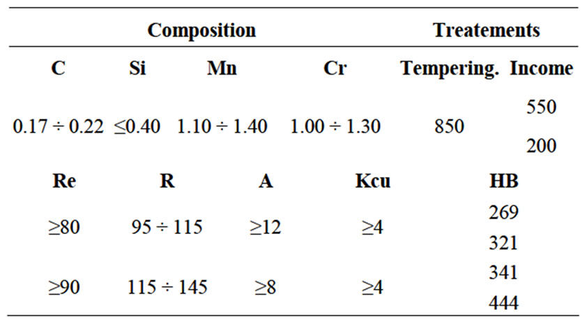
Table 1. Caracteristics of Fk20MnCr5.
work undertaken within the framework of this study shows that the various cutting tools change the cutting conditions of materials.
2.1. Determination of the Entry Parameters
The entry parameters to be defined are referred to:
• The cutting tools and coatings selected,
• The machined materials whose mechanical properties of workability will aim at differentiating the behaveiour from the tungsten carbide coatings.
• The cutting conditions adopted on a machine tool better adapted to an experimental design.
2.1.1. Tools and Coating
To define a tool, a great number of geometrical data enter in account:
• The choice of the substrate (mechanical cutting tool behaviour).
• The cutting edge shape.
• The cut angle: pressure angle on the part.
• The shape breeze chip intended to attenuate the wear of the tool by limiting the chip friction surface on the tool.
It is thus essential to set operating conditions as reproducible and simple as possible. This is why, it was selected:
• The tool carrying carbide cutting insert shape fixed and adapted to the turning conditions (reference CTGPL 16 16 K16 [14]).
• A not comprising chip breakers carbide cutting insert shape, since it introduces an additional variability into the chip flow on the tool and must be adapted to the coating.
2.1.2. Carbide Cutting Insert Description
The selected carbide cutting insert (Figure 1) is reverseble, Sandvik type (reference: TPMN 16 03 08) comprising three cut edges by carbide cutting insert [14].
2.2. Cutting Geometry
Several parameters are influencing the cutting geometry:


Figure 1. Sandvik carbide cutting insert TPMN 16 03 08 [14].
• The type of machining: here slide-lathing
• Orientation space carbide cutting insert compared to the machined material.
2.3. Machined Material
The behaviour of the coatings and their wear depend on the machined matter and its crystalline state, because the cutting mechanical conditions depend on the matter characteristics. It is thus significant to take account of this effect. The used matter during the experimentation is slightly allied steel soaked with fine grains, Fk20MnCr5, used in industry, initially, with a 50 mm on diameter and 500 mm in length.
2.4. Cutting Parameters
The general framework selected to test our coatings is slide-lathing. It results from it that we can schematize the configuration of the cut by the following drawing (Figure 2):
It is necessary to define the machining parameters, in order to avoid to be placed under cutting edge degradation conditions too fast.
To define these parameters, it is necessary to delimit first of all the entry field. This last was defined in order to limit the wear phenomena. Once the field is fixed, it is appropriate to fix the cutting conditions.
2.4.1. Cutting Speed
For the determination of the cutting speeds we used the coatings under industrial tests conditions, i.e. under optimal but very likely, different machining conditions [15].
The objective is to study the deterioration of the coatings. That poses a certain number of additional questions because, like we noted in the preliminary tests, the deterioration determination is generally not accessible by direct controls means.
Consequently, we can test the coatings under the same conditions and to compare the results obtained in:
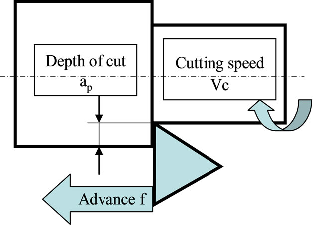
Figure 2. Machining configuration.
• Lifespans,
• Minimum cutting forces,
• Surface qualities of the machined part, etc.
But, this simple procedure presents a double disadvantage:
• It deliberately challenges the couple tool-matter con- -cept, on which machining in the industrial world is founded,
• It does not satisfy a scientific step, if it leads to tests out of the using intrinsic optimal zones of the coatings in machining. Moreover, the conclusions of such tests would have only a little interest for industry.
According to [15] for an operation of light outline, to machine slightly allied steel with a coating carburizes metal (the case of material and the carbide cutting insert used) under industrial conditions, the cutting speeds are limited to 85 m/min. For the experimental case, the cutting speeds vary from 45 to 77 m/min.
2.4.2. Feed Cutting Tool
This study is situated within the framework of a light outline, which forces to limit feed tool speeds. We know that roughness Ra can be determined according to the geometry of the tool, the feed and the cutting depth, in accordance with Figure 3.
In order to have an acceptable surface quality and to do not degrade the parameter Ra, it is necessary to have a minimal feed. However, it is also significant to take account of a minimum speed required in feed by the formation of a chip having a sufficient and no thickness.
Indeed, below a lower limit, the machined matter is crushed by plasticization and slips under the tool, generating a significant wear by abrasion. In order to locate, as much as possible, these tests under industrial conditions, according to [15] the feed value is 0.1 mm/tr. For our case the feed value is 0.11 mm/tr.
2.4.3. Cutting Depth
In order to present the surface quality criterion industrially primordial, under the light outline machining conditions, we must also limit the cutting depth in an interval
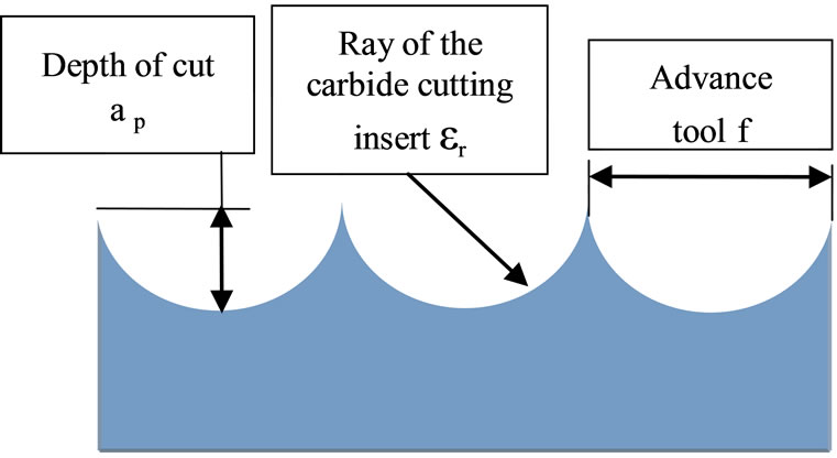
Figure 3. Bond between surface quality, feed tool and depth of cut.
well determined; for that, and according to [15] cutting depths vary from 1.5 to 4 mm. For our case the cutting depth is 1.5 mm.
2.5. Machining and Measurement Procedures
Slide-lathing was selected like machining operation in this experiment (Figure 4). The cutting conditions applied during this experiment are given in the Table 2.
Microscopy analyses with a microscope L2000-A indicate that for certain cutting conditions, wear by diffusion strongly prevails, the image acquisition was done by a numerical camera Canon Power Shot G5 type (Figure 5). These analyses were undertaken at the Laboratoire Mécanique des Matériaux et Maintenance Industrielle Structure (LR3MI) Annaba University—Algéria.
The measurements were carried out on a threedimensional measuring site without contact equipped with a High Resolution Sensor (HRS) (Figure 6) at the Laboratoire de l’Equipe d’Analyse et de Modélisation des Systèmes Mécaniques et de leurs Signatures (EA(MS)2) de l’Institut Universitaire de Technologie d’Aix en Provence—France.
3. Observations
1) During machining, the chip is formed, and it consists of isolated elements which we can say torn off from the primary material. They have varied shapes whose are not related one to each other.

Figure 4. Test-tube and tool used for the tests in machining.
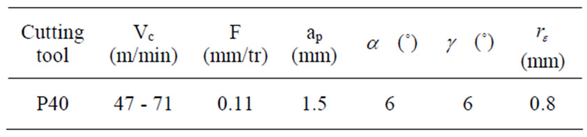
Table 2. Values of the cut parameters and the tool geometry.

Figure 5. Microscope L 2000 A.

Figure 6. Measuring site.
2) The feed slope is formed immediately, along the whole shearing surface on which the separation between the chip and the basic metal is carried out.
3) Such a chip leaves a rough machined surface overgrown with important hollows and peaks. The chip elements move slightly on the attack surface.
4) The chip can be discontinuous; in this case, the material cut off from the part in the cutting splits up almost at once that is detached.
5) It can be continuous, in this case, the the material cut off from the part does not split up; it becomes deformed under the cutting action. But it can also happen that the continuous chip adheres to the tool under the influence of disturbing elements, temperature and frictions.
Because of the formation of various types of chips (according to machining conditions), the appearance of a reported edge on the generated surface was noticed (Figure 7).
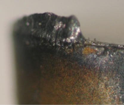

Figure 7. Reported edge.
This reported edge increases until it is evacuated towards the chip or the part; in this last case, it can result on a deterioration of the surface part quality During this experiment, a variation of the carbide cutting insert radius topology was noticed, as showed in Figure 8. A brought back edge was formed on the ray of the carbide cutting insert.
We succeed to eliminate the reported edge by increasing the cutting speed and decreasing the feed i.e. by reducing the machining output.
The reported edge mechanism is of a great practical importance, it is due to a wear by adhesion, since the rupture occurs in the chip mass and the chip fragments come to adhere on the tool by diffusion, which modifies the part dimensions of the machined part as well as the surface quality.
From the undertaken test investigation, it will be necessary then to develop a methodology making characterization possible, and to define the influence of the cutting parameters (modes of wear) but especially to understand the influence of the evolution of the coatings wear on the surface quality and the integrity of the finished part [16].
The works undertaken in this study, show that the coatings change the cutting conditions of materials on the formation level of the chips as well as on the required energy cutting level. Analyses in microscopy indicate that for certain cutting conditions, the wear by diffusion strongly prevails.
After the reported edge elimination, a crater is generally formed on the metal carbide carbide cutting insert surface (Figure 9) generally due to the crumbling i.e. the wrenching of small particles of the metal tool (Figure 10),
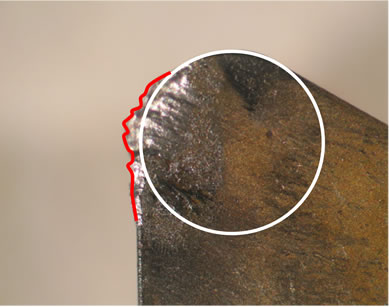
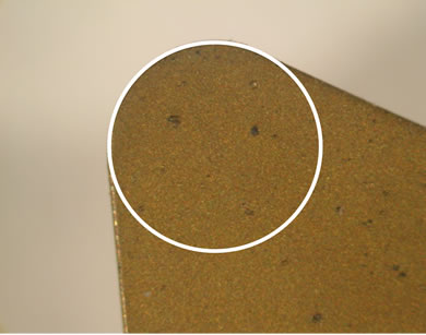
Figure 8. Variation of the carbide cutting insert Ray topology.
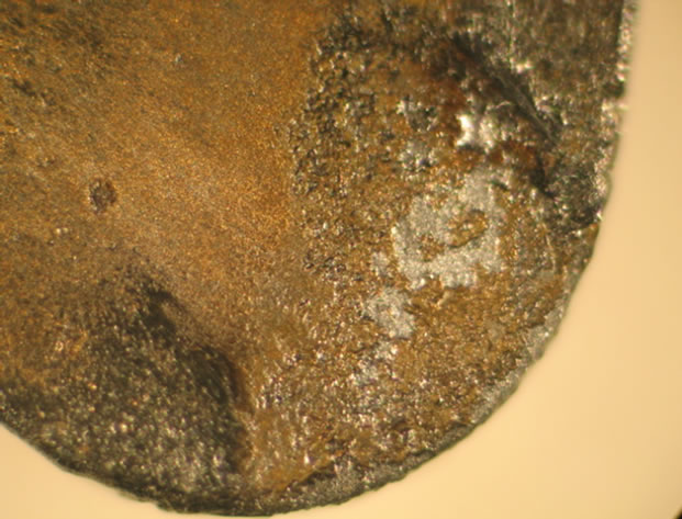
Figure 9. Sight of the generated surface of the carbide cutting insert with the crater.

Figure 10. Sight of the generated surface of the carbide cutting insert with crater.
while they remain strongly resistant to the abrasive wear The crater was picked up through the measurements taken on the metal carbide carbide cutting insert by using the HRS
4. Results and Interpretations
From the conducted test investigation it will be necessary to develop a methodology allowing characterizing the carbide cutting insert wear, to define the influence of the cutting parameters (modes of wear) but especially to understand the wear evolution influence of the coatings on the surface quality and the finished part integrity [16].
The use of the HRS equipped 3-D measuring without contact station has permitted to trace the various wear shapes, the number of points obtained through various measurements, as well as the real tracing of the nozzle ray variation of the used carbide cutting insert, and the cutting face (Figure 11).
The number of points recorded by the sensor at each of its displacements is of 1000 points, and the number of passes is 65, which gives a number of 65,000 points for each measurement (Figure 12).
But for the following calculations, 64 points will be taken into account, which represents the real pace of the

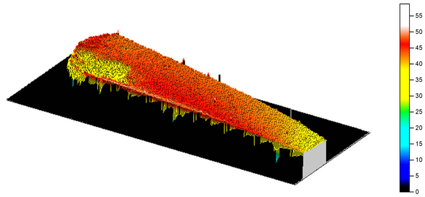
Figure 11. Carbide cutting insert surface in 2D and 3D.
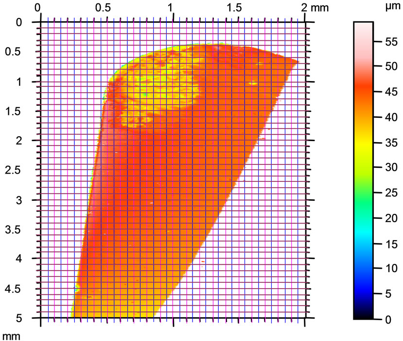
Figure 12. Procedure to obtain the 64 points constituting the nozzle ray variation.
nozzle ray variation (Figure 12). For that, the edge topography was divided into regular steps having variation Δx = 50 µm and Δy = 100µm.
The goal is to define the wear equation for a uniform curve passing by the 64 points of control which represents the real pace of the nozzle radius variation (Figure 13).
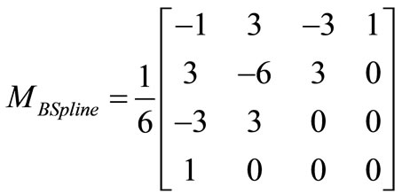
To define the equation of this wear, we used the B Spline method expressed by the following relation:
 (1)
(1)
with:
•  : co-ordinates of the control points,
•  : The matrix of B Spline given by:

Figure 13. Real pace of the nozzle ray variation.
 (2)
(2)
We found 16 equations, each one of them is the interpolation of 4 points with the B Spline method. The results obtained are:
 (3)
(3)
 (4)
(4)
Hence the last equation:

Figure 13 gives a representative form of the real pace of the nozzle ray variation after interpolation with the B-Spline method.
5. Conclusions
The cutting operation consists in transforming a material into a part by the action of tools animated by a machine tool. It is carried out by efforts, couples and heating, which generally moves and fluctuates during the operation and which are likely to compromise the respect of the dimensional tolerances.
In the zones of strong pressure on the edge of cut, deterioration is manifest since the first passes. The coatings which have a very low thickness of deposit, about a few microns, are thus eliminated from the initial edge of the tool from the first seconds of machining. We deduce that this presence is enough to modify the cutting conditions.
On the other hand, we identified deterioration modes of the tungsten carbide coatings: abrasion, diffusion, surface heating, plastic deformation, cracking, etc, as well as the formation of a brought back edge.
The experimental device used made it possible to better see the real wear pace of the cutting face. The mathematical model suggested facilitated the deduction of this pace by the interpolation of this result by using the method of B-Splines method.
Finally, the surface elaboration process of or the cutting process can be considered as creation of a surface with a prescribed precision and roughness on the machined part, by the mean of the relative movement toolpart, carried out by the machine tool.
6. REFERENCES
- J. X. Deng, W. L. Song, H. Zhang, P. Yan and A. H. Liu, “Friction and Wear Behaviours of the Carbide Tools Embedded with Solid Lubricants in Sliding Wear Tests and in Dry Cutting Processes,” Wear, Vol. 270, No. 9-10, 2011, pp. 666-674.
- K. Kudou, T. Ono and S. Okada, “Crater Wear Characteristics of an Fe-Diffused Carbide Cutting Tool,” Journal of Materials Processing Technology, Vol. 132, No. 1, 2003, pp. 255-261. doi:10.1016/S0924-0136(02)00936-6
- X. Luo, K. Cheng, R. Holt and X. Liu, “Modeling Flank Wear of Carbide Tool Insert in Metal Cutting,” Wear, Vol. 259, No. 7-12, 2005, pp. 1253-1240. doi:10.1016/j.wear.2005.02.044
- D. K. Born and W. A. Goodman, “An Empirical Survey on the Influence of Machining Parameters on Tool Wear in Diamond Turning of Large Single-Crystal Silicon Optics,” Precision Engineering, Vol. 25, No. 4, 2001, pp. 247-257. doi:10.1016/S0141-6359(00)00069-6
- S. Y. Liang and D. A. Dornfield, “Tool Wear Detection Using Time Series Analysis of Acounstic Emission,” Journal of Engineering for Industry, Vol. 111, No. 3, 1989, pp. 199-204. doi:10.1115/1.3188750
- T. I. EI-wardany, D. Gao and M. A. Elbestawi, “Tool Condition Monitoring in Drilling Using Vibration Signature Analysis,” International Journal of Machine Tools and Manufacture, Vol. 36, No. 6, 1996, pp. 687-911. doi:10.1016/0890-6955(95)00058-5
- W. B. Lee, C. F. Cheung, W. M. Chiu and L. K. Chan, “Automatic Supervision of Tool Wear Using Pattern Recognition Analysis,” International Journal of Machine Tools and Manufacture, Vol. 37, No. 8, 1997, pp. 1079- 1095. doi:10.1016/S0890-6955(97)88104-7
- L. Wang, M. G. Mehrabi and E. Kannatey-Asibu Jr., “Hidden Markov Model-Based Tool Wear Monitoring in Turning,” Journal of Manufacturing Science and Engineering, Vol. 124, No. 3, 2002, pp. 651-658.
- Y. Karpat and T. Ozel, “Mechanics of High Speed CutTing with Curvilinear Edge Tools,” International Journal of Machine Tools & Manufacture, Vol. 48, No. 2, 2008, pp. 195-208. doi:10.1016/j.ijmachtools.2007.08.015
- H. Saglam, S. Yaldiz and F. Unsacar, “The Effect of Tool Geometry and Cutting Speed on Main Cutting Force and Tool Tip Temperature,” Materials and Design, Vol. 28, No. 1, 2007, pp. 101-111. doi:10.1016/j.matdes.2005.05.015
- K. Bouacha, M. A. Yallese, T. Mabrouki and J. F. Rigal, “Statistical Analysis o Surface Roughness and Cutting Forces Using Response Surface Methodologie in Hard Turning of Ainsi 52100 Bearing Steel with CBN Tool,” International Journal of Refractory Metals & Hard Materials, Vol. 28, No. 3, 2010, pp. 349-361.
- M. A. Yallese, K. Chaoui, N. Zeghib, L. Boulenouar and J. F. Rigal, “Hard Machining of Hardened Bearing Steel Using Cubic Boron Nitride Tool,” Journal of Materials Processing Technology, Vol. 209, No. 2, 2009, pp. 1092-1104. doi:10.1016/j.jmatprotec.2008.03.014
- H. Gökkaya and M. Nalbant, “The Effects of Cutting Tool Geometry and Processing Parameters on the Surface Roughness of AISI 1030 Steel,” Materials and Design, 2005.
- Lathing Tools, Sandvik Cormant, 2000. www.sandvik.coromant.com
- R. Pavel, et al., “Effect of Tool Wear on Surface Finish for a Case of Continuous and Interrupted Hard Turning,” Journal of Materials Processing Technology, Vol. 170, 2005. pp. 341-349. doi:10.1016/j.jmatprotec.2005.04.119
- J. Wang, C. Z. Huang and W. G. Song, “The Effect of Tool Flank Wear on the Orthogonal Cutting Process and Its Practical Implications,” Journal of Materials Processing Technology, Vol. 142; 2003, pp. 338-346. doi:10.1016/S0924-0136(03)00604-6