Intelligent Control and Automation
Vol.4 No.4(2013), Article ID:39507,5 pages DOI:10.4236/ica.2013.44048
Stable and Adaptive Control for Wheeled Mobile Platform*
Department of Electrical Engineering, École Polytechnique, Montréal, Canada
Email: sousso.kelouwani@polymtl.ca, christian.ouellette@polymtl.ca, paul.cohen@polymtl.ca
Copyright © 2013 Sousso Kelouwani et al. This is an open access article distributed under the Creative Commons Attribution License, which permits unrestricted use, distribution, and reproduction in any medium, provided the original work is properly cited.
Received June 9, 2013; revised July 9, 2013; accepted July 16, 2013
Keywords: Robotic Control; Lyapunov Stability; Nonholonomic Control; Differential Drive; Powered Wheelchair
ABSTRACT
Most differential drive platforms are equipped with two independent actuators and casters. The positions of the gravity center and the rotation center often do not coincide. This position difference, combined with the effect of unbalanced actuator dynamics on the motion, makes it difficult to properly control the platform. We propose an adaptive nonlinear controller system based on the Lyapunov stability theory that greatly improves the trajectory tracking performance of such platforms. The asymptotically stable kinematic controller takes into account the position difference and the effect of the unbalanced actuator dynamics. The dynamic controller has the desirable property that it requires minimal knowledge of the platform physical parameters. Validation was performed through simulation and several experiments conducted on a rear driven powered wheelchair. Comparative experimental studies suggested that the proposed adaptive control system performs better than a similar method presented in the literature for linear as well as curvilinear trajectory tracking. Furthermore, the control system exhibits good tracking performance on inclined plans and non smooth surfaces.
1. Introduction
Stable trajectory tracking is one of the most important problems of underactuated mobile platforms with nonholonomic constraints [1]. Over the passed decades, wheeled mobile platforms actuated by means of two different motors have been among the most studied mobile systems [2-5]. The potentially wide range of applications justifies this intense research effort. Reference trajectory tracking involves the design of stable control law that allows the platform to follow a given reference path. However, according to Brockett’s theorem [6], a nonholonomic mobile platform cannot be asymptotically stabilized to an equilibrium point with the use of a smooth continuous state feedback control law. To overcome this condition, several approaches have been proposed in the literature. These approaches fall into three main categories, namely kinematic control laws based upon the well-known perfect velocity tracking model [7,8], kinematic-dynamic control laws [9,10] and adaptive dynamic control laws [5,11-15].
The kinematic control law approach assumes that the control signals produce the exact motion commanded [16]. Chang [17] proposed a kinematically stable solution for a nonholonomic platform in polar coordinates. A nonlinear state feedback stabilization control law was presented and validated through simulation study. Kanayama [8] proposed a stabilizing control law using the Lyapunov design approach with a cartesian coordinate formulation of the tracking problem. In [18], a feedback control using nonlinear oscillators is presented and the theoretical kinematic stability is established. While the perfect velocity tracking assumption simplifies the kinematic controller design, it totally ignores the important dynamic aspects of the platform [13].
The kinematic-dynamic approach considers the two aspects (kinematic and dynamic) of the mobile platform control and assumes that the actuator inputs signals are torques instead of velocities [19]. Accordingly, Astolfi [10] used the polar representation of the mobile platform and proposed a discontinuous control law that provides an exponential stabilization. Other papers report the design of stabilizing control laws with platform cartesian representations [20]. While this type of approach accounts for dynamic aspects, it may be sensitive to disturbances that affect the platform motion in real applications.
The third category is related to the robust and adaptive dynamic design approaches. Their main objective is to overcome the weakness of the previous approaches by taking into account the unavoidable disturbances caused by the navigation environment [12,21]. Most recent publications on the reference trajectory tracking with nonholonomic platforms use adaptive dynamic approaches. [22] studied the effect of wheel skidding on platform stability when a Lyapunov based kinematic controller is used. The system is shown to be stable under certain conditions. The sliding mode control provides fast response and good robustness in presence of platform model uncertainties [23,24]. In [13], an adaptive sliding mode design approach using a self recurrent wavelet neural network is described and validated through simulation. In [5], an adaptive dynamic control scheme using the nonlinear stochastic control is proposed. This scheme is mainly based upon the dual control principle originally proposed by Fel’Dbaum [25]. The advantage of this method seems to be its ability to achieve at the same time the control of the platform and parameter estimations. Although successfully extensive simulations were provided, no experimental validation was shown. Adaptive fuzzy control can be used to approximate nonlinear functions. This method has been extensively studied in control theory. Hou [11] designed an adaptive controller based on the backstepping [26] and fuzzy logic approaches. It takes into account the uncertainty in the platform kinematic and simulation results suggest good performance. In [27], the backstepping technique is also used to design a stable dynamic controller for car-like platform and the reference trajectory tracking performance is evaluated in simulation. However, the performance of backstepping control is dependent upon knowledge of the exact platform model. Hence, it applications on real mobile platforms may be limited [14]. Venelinov [14] proposed another adaptive fuzzy approach using a kinematic controller. This method was able to reduce in simulation the effect of unmodeled disturbances. In [28], a dynamic Petri recurrent fuzzy neural network was proposed and its performance for the reference trajectory tracking were compared with other similar methods. The tracking error was demonstrated to convergence to an equilibrium point through different learning rates obtained by applying Lyapunov stability theory to the system. In [29], a robust control of a nonholonomic mobile robot is presented using the backstepping of the kinematics into the dynamics. The adaptive controller was based on a neural network, and the overall control system was testing in simulation. Whilst this approach is shown to be stable in presence of unmodeled bounded perturbations, the size of this neural network as well as the time convergence property of the whole system is difficult to assess. Moreover, in practice, it is not simple to get a real-time implementation of the adaptive neural network controller.
Although most these works were successfully tested in simulations, few experimental studies have been presented to help assess controller behavior. Furthermore, the studies considered simple disturbance models that may not be encountered in real mobile platform applications. Experimental validation under different operation conditions should provide a better understanding of the practical strengths and weaknesses of each proposed controller design.
Besides the lack of experimental validation, most controller design approaches assume that the two actuators dynamics are fully compensated or matched. The full compensation assumes that the actuators behave in the same way under the same operation conditions.
When the above assumptions are not verified on real navigation platforms, the reference trajectory tracking performance decreases. Indeed, it was mentioned in [10] that the difference between wheel radius is one the most common modeling error. In [12,30], it was shown that in practice, ensuring that two different actuators behave identically, even when working under similar operating conditions, is far from trivial. Some authors considered such mismodeling as model uncertainty and, therefore, rely on the adaptive control laws to reduce their impact on the platform trajectory tracking process [13,5].
The goal of this work is to propose a straightforward controller design approach for a class of nonholonomic mobile platform that improves the reference trajectory tracking performance. The controller accounts for:
• the positional difference between the rotation center and the gravity center of the platform;
• the effect of the unmatched actuator dynamics on the platform motion;
• external disturbances during the trajectory tracking.
To achieve this goal, we propose an adaptive controller with two components: a stable kinematic controller and a stable dynamic controller. The kinematic controller provides the required velocities to track the reference path. These velocities may not be properly transformed into motion by the platform actuators due to the presence of various disturbances such as caster orientations, variable load and variable friction conditions between wheels and the navigation environment. In addition to these external disturbances, the platform model is affected by parameter estimation uncertainties related to the center of gravity position, the center of gyration position, the system mass and inertia, etc. An adaptive control approach is adopted since this approach does not require the knowledge of the complete system model. The merits of the approach presented here may be enumerated as follows:
• a stabilizing kinematic control law that tolerates unbalanced actuators dynamics;
• a stabilizing control law for the dynamic controller, based upon the model reference adaptive approach, that reduces significantly the effects of external disturbances and model parameter estimation uncertainties;
• validation experiments of the proposed control system on a real mobile platform under different operation conditions;
• an experimental comparative study between the proposed approach and similar approaches found in literature.
The rest of the paper is organized into four sections. Section II presents the differential drive platform model. Based upon this model, we present in section III the design of new nonlinear kinematic and dynamic controllers. The validation of the proposed approach is presented in section IV and the conclusion is presented in section IV.
2. Differential-Drive Mobile Platform Model
We propose a dynamic and kinematic model for a mobile platform actuated by two independent electrical motors as illustrated in Figure 1. The related nomenclature description used throughout this paper is as follow:

Figure 1. Representation of the Navigation Environment: C is the midpoint of the axis that joined the two driving wheels. G is the gravity center position in the platform reference frame.
• C: the midpoint of the axis that joined the two driving wheels. It is the origin of the platform reference frame;
• X and Y are respectively the abscissa axis and the ordinate axis of the global reference;
• G: the gravity center position in the platform reference frame ;
;
• a: the positional difference between C and G;
• m: platform and the load total mass;
• i: the platform and the load inertia about C;
The following assumptions are made:
Assumption 2.1 Each wheel mass is negligible compared to the total mass of the platform and the load (m).
Assumption 2.1 The wheels roll without slippage and, therefore, no velocity component perpendicular to the wheel planes is present.
Assumption 2.1 The actuators are fully compensated, i.e. all their electromechanical parameters are perfectly matched. This assumption is only used to formulate the ideal dynamic state equations.
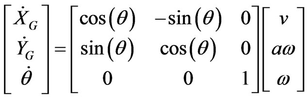
Based on the well-known Newton-Euler equations [31] and by taking into account assumptions 2.1, 2.1 and 2.1, the state equations are represented by the following equations [5,32]:
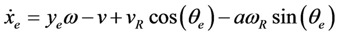
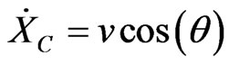 (1)
(1)
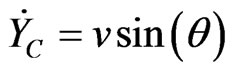 (2)
(2)
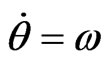 (3)
(3)
where  and
and  are the measures at
  of the linear and angular velocities respectively.
  and
and  are the position of
  in the global reference frame. According to assumption 2.1 the following constraint is formulated:
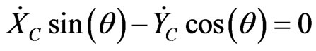 (4)
(4)
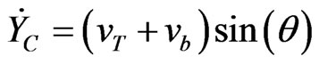
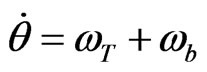
Expressions (1), (2) and (3) represent the platform kinematic model.
In real applications, assumption 2.1 is not always true and bias velocities are added to  and
and . Hence,
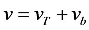 (5)
(5)
and
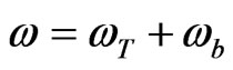 (6)
(6)
where  and
and  are nominal linear and angular velocities respectively when the actuator dynamics are perfectly balanced.
  and
and  represents the linear and angular bias velocities induced by the propulsion force mismatch, respectively. Kinematic expressions (1), (2) and (3) become:
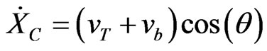 (7)
(7)
 (8)
(8)
 (9)
(9)
Most existing controllers neglected parameters  and
and  in their kinematic model, therefore negatively affecting the tracking ability.
3. Non-Linear Controller Design
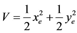
3.1. Preliminaries
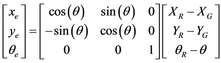
At each instant , a virtual platform kinematically identical to the real platform is moving along the reference trajectory illustrated in Figure 1. The tracking problem consists of designing a controller that minimizes the tracking error represented by the following expression [8]:
 (10)
(10)
where the reference configuration (the configuration of the virtual platform) and the real configuration at a given time are designated by 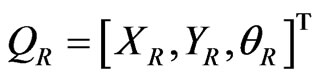 and
and 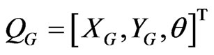 .
.
Unlike most approaches in the literature, the error is expressed relative to , the configuration error represented by expression (0.10) is related to
 . With the proposed configuration error formulation, the distance between
  and
and  can be taken into account in the controller design.
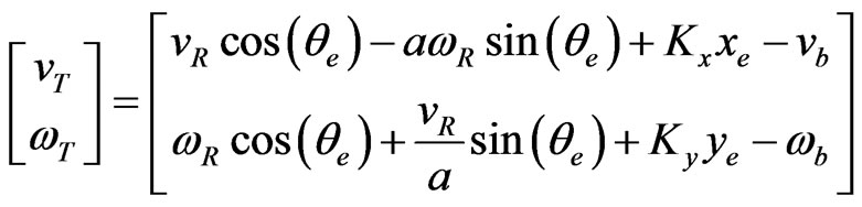
We adopt the control architecture illustrated in Figure 2. Given the reference configuration  and the reference velocities
 , the role of the kinematic controller is to propose target velocities
  based on assumptions 2.1 and the perfect velocity tracking assumption. The dynamic controller is designed in order to compensate for unmodeled dynamic behavior and help the overall controller to better track the reference trajectory. Since most DC motors are torque driven, the dynamic controller will generate the required accelerations
  for actuators.
3.2. Kinematic Controller Design
The following assumptions are made:
Assumption 3.1 The kinematic control law is based upon the assumption of perfect velocity tracking which assumes that the control signals  exactly produces the desired motion.
Assumption 3.1 ,
,  and
and  are known. Furthermore,
  is a strictly positive constant.
Given  and
and  relatively to
 , the expression of
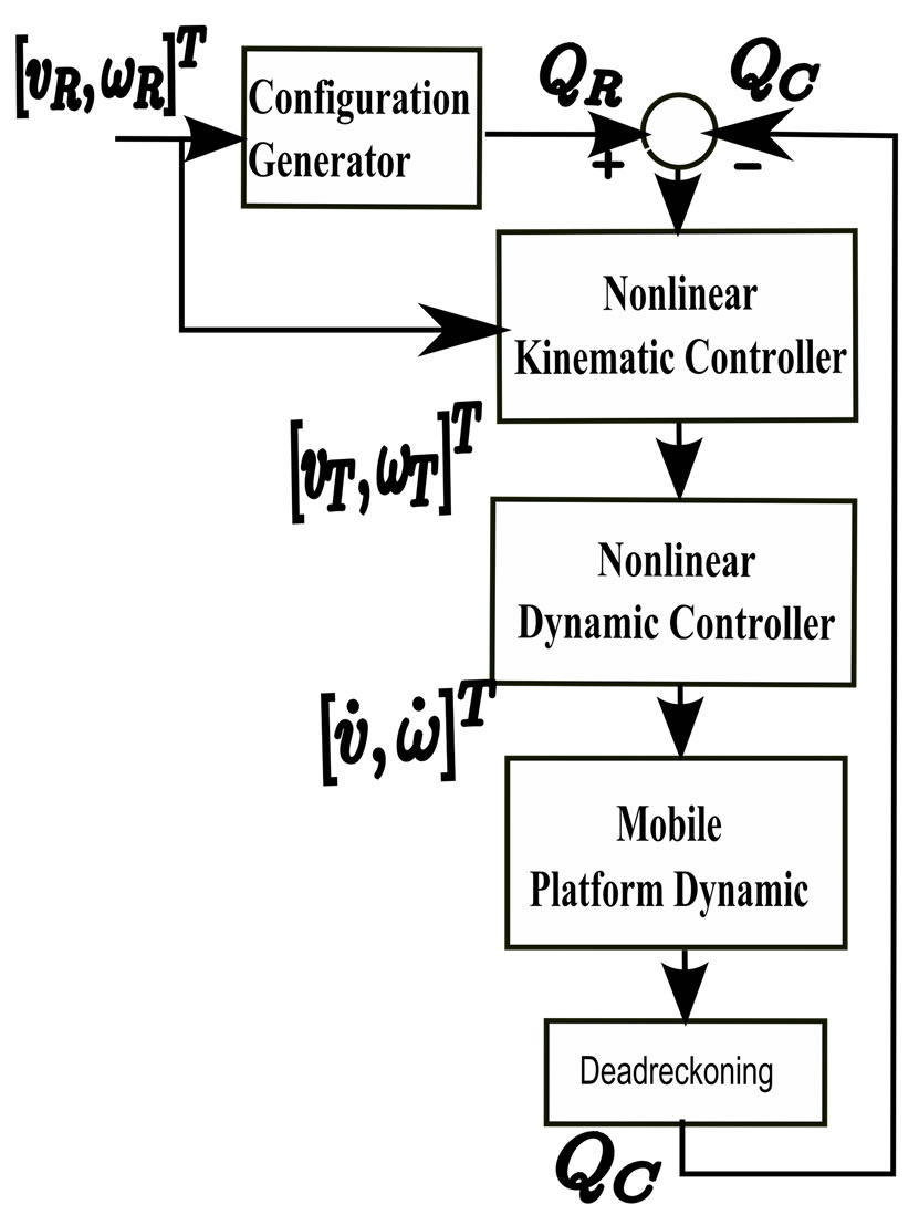
Figure 2. Platform Control Bloc Architecture.
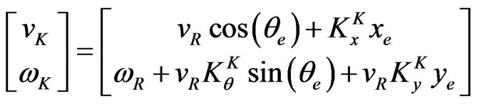
the velocities at  are:
are:
 (11)
(11)
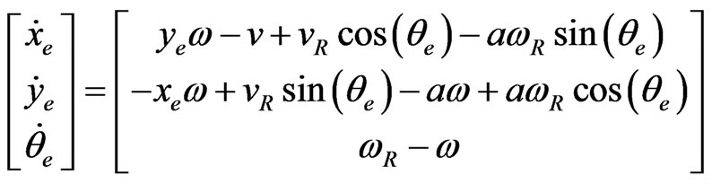
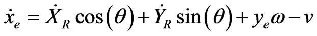
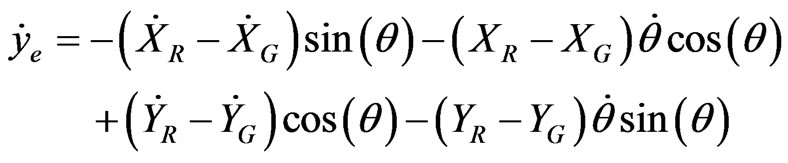
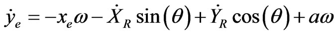
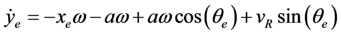
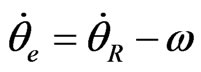
Proposition 3.1 It can be shown (see appendix A) that the derivative of the configuration error is given by:
 (12)
(12)
where  and
and  represent the reference linear and angular velocities, respectively.
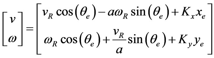
To build the kinematic controller, let us consider the following nonlinear control laws:
 (13)
(13)
where  and
and  are bounded positive constant values.
Proposition 3.1 When kinematic control laws (13) are used, it can be shown (see appendix B) that the errors  converge asymptotically toward
  .
.
In the following proposition, we demonstrate that under certain conditions, the configuration error  converge locally to
 .
.
Proposition 3.1 Assume that  and
and  are continuous and bounded and their derivative are small. It can be shown (see appendix C) that the system using control laws (13) is locally asymptotically stable.
For practical application, the assumption 3.1 may not be true. In the following section, we propose an adaptive dynamic controller that is an extension of the kinematic controller.
3.3. Dynamic Controller Design
The exact values of the system mass , the system inertia
 , the distance between the center of gravity and the center of rotation
  and the bias velocities
  are not trivial to obtain. Moreover, the friction conditions between the wheels and the navigation surface as well as the caster orientations are some of the usual sources of perturbations that can seriously degrade the trajectory tracking performance.
Differents approaches have been studied in order to reduce the negative effects of some of these perturbations on the platform motion [10,22,13,25,11,27,14]. In practice, it is desirable to have a dynamic controller that does not require the knowledge of the complete system model. The adaptive control approach based upon the model reference principle is a good candidate for designing the dynamic controller [33]. Moreover, this approach is straightforward.
The role of the dynamic controller illustrated in Figure 3 is to generate the required accelerations  so that the platform will move at velocities
  suggested by the nonlinear kinematic controller, regardless of the presence of the aforementioned disturbances. More formally, two reference models for linear and angular velocities
  are given (refer to Figure 3) with inputs and outputs as are
  and
and , respectively. The platform, whose parameters are unknown, has
  as inputs and
  as outputs. The goal of the dynamic controller is to provide
  so that
  asymptotically tracks
 .
.
In order to guarantee the stability of the overall control system, we adopt the adaptive controller design approach based on the Lyapunov method [33]. Therefore, a dynamic controller is designed for the linear velocity  and another one is designed for the angular velocity
 .
.
3.3.1. Linear Velocity Dynamic Controller
The design requires two steps, namely the selection of the reference model that should be tracked by the system and the design of a stabilization control law.
3.3.2. Linear Velocity Reference Model
In the absence of disturbances and when the perfect velocity tracking assumption is used, the accelerations
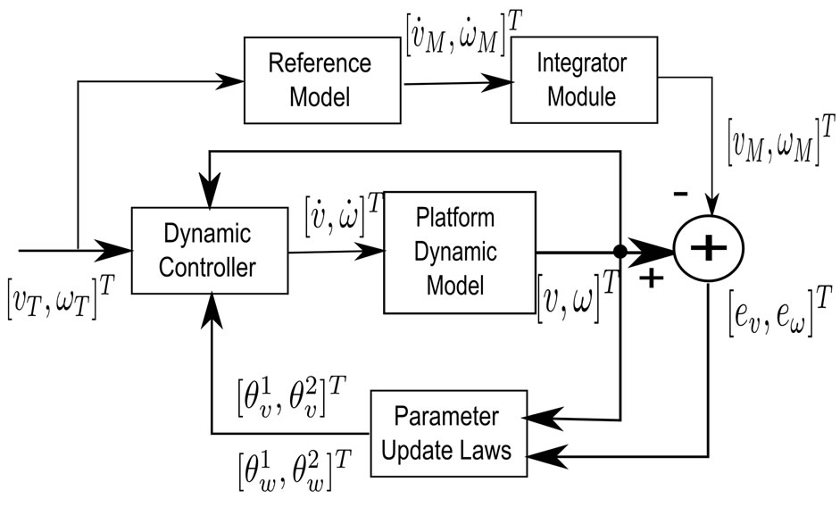
Figure 3. Model Reference Adaptive Control.
 and
and  should be identical. Any presence of disturbance will lead to a deviation between the platform velocity
  and the model velocity
 . So we propose the following velocity reference model:
 (14)
(14)
where  is the linear acceleration.
  is a parameter that is linked to the desired dynamic performance.
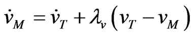
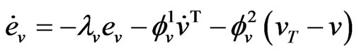
3.3.3. Linear Velocity Reference Model Tracking
To allow  to track
  asymptotically, we propose the following expression:
 (15)
(15)
where  and
and  are control parameters that must be adapted. The proposed control law has an anticipative component
  and a corrective part
  similarly to the reference model (refer to expression (14)). Perfect linear trajectory tracking is obtained when
  and
and . To find the adaptive law for the two control parameters
  and
and , we propose the following definition of the tracking error:
 (16)
(16)
Proposition 3.1 Assume that  and
and  are bounded. Consider the following adaptive laws:
 (17)
(17)
 (18)
(18)
where  is a constant.
If the control law (15) is used with the adaptive laws (17) and (18), it can be shown (see appendix D) that the tracking error  converges asymptotically to 0. Furthermore, the global tracking error
 ,
,  and
and  are bounded and we showed that it is possible to let these errors to be as small as possible (see appendix D).
3.3.4. Angular Velocity Dynamic Controller
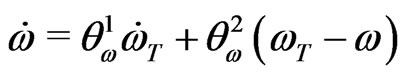
The angular velocity dynamic controller design follows the approach presented in section %d.0.3.3. The reference model is represented by:
 (19)
(19)
where  is the angular acceleration and
  is a parameter that is linked to the desired dynamic performance.
The control law is given by:
 (20)
(20)
where  and
and  are parameters to be adapted. The angular velocity error is:
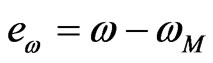 (21)
(21)
By using the Lyapunov function represented by the expression (22), we obtained the adaptive laws (23) and (24).
 (22)
(22)
where  and
and .
.
 (23)
(23)
 (24)
(24)
3.4. Discussion
1) From expression (30) (refer to Appendix B), it is clear that the stability condition is not dependent upon velocity biases . Although the positional difference between the center of gravity and the center of rotation is part of the Lyapunov derivative function, it contributes to the kinematic stability.
2) The platform motion smoothness is an important factor for real applications [8]. A smooth motion can be obtained if the following conditions are satisfied [8]:
• the reference trajectory is continuous;
• the reference trajectory curvature is also continuous;
• the reference control signals  and their derivatives
  are bounded.
• the control coefficients  should be set in order to satisfy predefined maximum acceleration and deceleration. Indeed, large values tend to make the system to converge faster, but they may cause motion oscillations.
3) The proposed dynamic controllers do not require knowledge of platform parameters. It can therefore be used with little effort on actual platforms. Furthermore, it can handle bounded perturbations, regardless of their sources.
4) In order to accelerate the convergence of ,
,  ,
,  and
and  estimations, their initial values
  can be set different to 0.
4. Simulation and Experimental Validations
The performance of the proposed approach has been analysed by simulation and experimentally through comparative studies with a similar method presented originally by Kanayama [8] and recently used by Bugeja [5]. The Kanayama kinematic controller was designed without taking into account the difference in positions between the gravity and the rotation centers and by assuming perfect velocity tracking. In order to use this controller in our comparisons, we used the dynamic controller of Section 3.3 as its natural extension [30]. In the remainder of this paper, we call it the Kanayama Tracking Controller (KTC) while the kinematic and dynamic controllers are designated as Improved Tracking Controller (ITC). The main result presented by Kanayama is the two following stabilizing kinematic control laws:
 (25)
(25)
where  and
and  are the Kanayama linear and angular velocities respectively;
 ,
,  and
and  are positive constant values.
4.1. Validation through Simulation
The simulation aims at assessing the proposed controller before conducting experimenting on a real mobile platform. Specifically, this study will show that ITC performs comparatively better than KTC on linear and curvilinear trajectories, even when the bias velocities  and
and  are not exactly known. Matlab software and a specific robotic middleware software called Acropolis [34] were used for the simulation.
4.1.1. Simulation Scenario
We consider a platform with a center positional difference . The bias velocities
  and
and  are represented by random variables:
 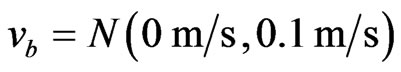 and
and  where
where  represents a gaussian process with mean
  and variance
 . The value of velocities used in the kinematic controller are represented by the random variable means:
  and
and . The dynamic controller parameters
 ,
,  ,
,  and
and  are set to 1.
From its rest configuration , the platform must follow a straight-line trajectory with a velocity of
 . It must then follow a curvilinear trajectory of
  of radius with
  and
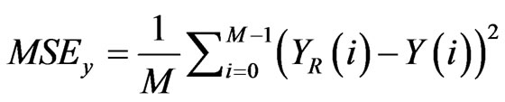
and  . All variables are discretized. The tracking mean squared error (MSE) is used as a comparison measure, as expressed by the three measures:
 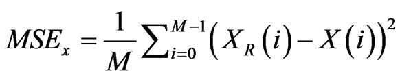 ,
,
 ,
,
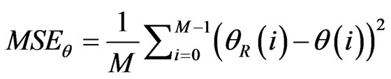 where M is the number of discrete values of the configuration during one run of the simulation.
The following parameter values are used:
• KTC approach: ,
,  and
and . The initial values of the dynamic controller are:
  ,
,  ,
,  and
and .
.
• ITC approach:  and
and . The initial values of the dynamic controller are:
 ,
,  ,
,  and
and .
.
4.1.2. Simulation Results
Figure 4 shows the trajectories obtained from simulation. Both the ITC approach and the KTC approach generate stable trajectories. Despite the presence of noise on the bias velocities, the trajectory produced by ITC (solid black curve) is very close to the reference trajectory (solid gray curve). The ITC performs better than the KTC as shown in the Table 1. This performance is mainly due to the kinematic controller proposed in this paper. Recall that the common part between the ITC and KTC is the dynamic controller. The four parameters ,
,  ,
,  and
and  had similar values regardless of the kinematic controller involved. Thus, the only way to explain the difference in performance lies in the kinematic controller behaviors. In Figure 5, the tracking errors
 ,
,  and
and  obtained with ITC are lower in the average than the tracking errors obtained with KTC.
4.2. Experimental Validation
4.2.1. Experiment Setup
Electric power wheelchairs actuated by two independent motors have been widely used to study tracking controllers and various navigation tasks [35,36,12]. Since the proposed tracking approach takes into account the positional difference between the rotation and the gravity centers, we selected a rear driven powered wheelchair (as illustrated in the Figure 6. To demonstrate the practical aspects of the proposed reference configuration tracking system, we conducted several experiments of rectilinear and curvilinear trajectory tracking. The platform model parameters as well as the controller parameters are summarized in Table 2. During all experiments, a load of 77 kg (corresponding to the user) was on the wheelchair and the front casters were always positioned perpendicularly to the motion direction at the beginning. This pose of casters adds a maximum disturbance to the motion. To determine the bias velocities, the wheelchair was lifted off the ground to avoid any contact between the wheels and the ground. No close loop controller was used. In order to find , the angular velocity was set to 0 and different values of linear velocities were used. An
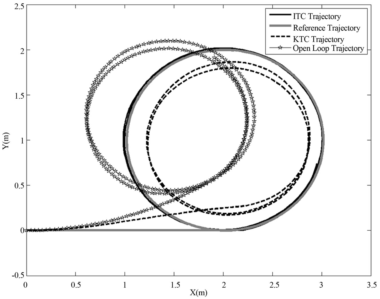
Figure 4. Tracking Ability Comparison Between Open-loop, KTC and ITC Controllers.
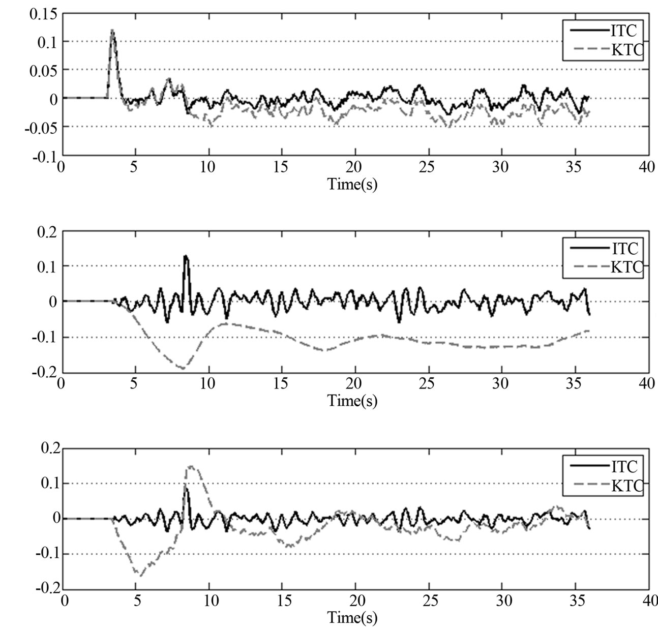
Figure 5. Comparative Tracking Error Between KTC and ITC Controllers.
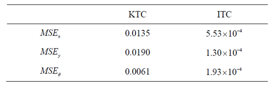
Table 1. Mean-Square Error Obtained from Simulation.

Table 2. Experimental Parameters.
angular bias velocity  was then observed. Similarly, by setting the linear velocity to 0 and using several values of angular velocities, a bias velocity
  was obtained.
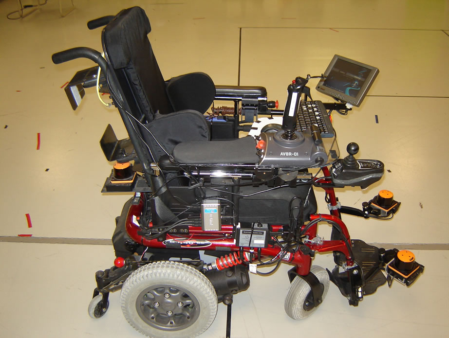
Figure 6. Rear Driven Powered Wheelchair Model Quickie 646 by Sunrise Medical.
4.2.2. Linear Trajectory Tracking
The objective of the first experiment is to demonstrate the convergence of the proposed controllers and to compare the performance of the ITC and the KTC approaches in rectilinear trajectory tracking. To test the convergence, the platform was given different initial configurations: ,
,
 ,
,  and
and . From one of these initial configurations, the proposed controllers must drive the platform to the configuration
  with the reference velocities
  and
and . Figure 7 shows the time evolution of the three tracking errors:
 ,
,  and
and . These errors approach zero, even if the reference angular velocity is set to 0.
In order to compare the ITC and KTC approaches in rectilinear trajectory tracking, the platform must track a linear trajectory of  with the reference velocities
  and
and . The initial configuration was set to
 . Ten trials were conducted. Figure 8 illustrates typical trajectories obtained without the controllers, using the KTC and the ITC controllers. These trajectories suggest that the ITC is able to maintain a deviation on the Y-axis less than
  while the KTC deviation if four times larger after
 . Tracking mean-square errors for the ITC and KTC are presented in Table 3.
4.2.3. Curvilinear Trajectory Tracking
The purpose of the second experiment is to compare the ITC and KTC controller tracking performances in the case of curvilinear trajectories. From its rest configuration at , the platform must track a trajectory generated by using the reference velocities
  and
and . Figure 9 illustrates typical trajectories obtained without controller, with the KTC and the ITC controllers.
These trajectories show that the ITC is able to maintain a deviation on the X-axis and Y-axis less than 0.4 m. Deviations produced by the KTC are substantially larger most of the time as shown in Figure 10. Tracking mean-square errors are presented in Table 4.
4.2.4. Linear Trajectory Tracking on Inclined Surfaces
Natural navigation environments include incline plans. We investigated the behavior of the ITC controller in the case of trajectory tracking on inclined plans as shown in Figure 11. Experiments consisted of starting from  and following a rectilinear path of
  length, climbing over a 2.5 cm denivellation at approximately 2.5 m, ascending a first
  incline of 1.25 m, rolling on a horizontal plane for approximately 1.2 m and descending a
  incline of 1.25 m and
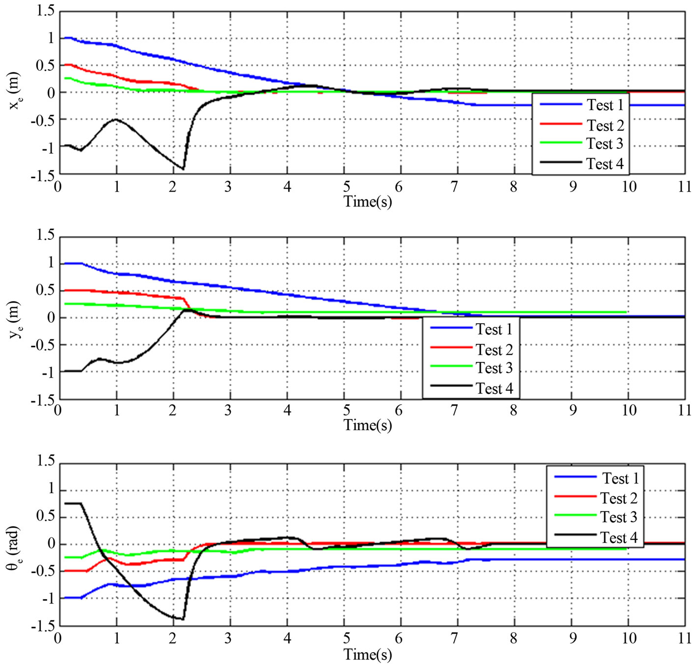
Figure 7. Tracking Error for Different Initial Platform Configurations: Test 1, Test 2, Test 3 and Test 4 correspond to initial configurations ,
,  ,
,  and
and , respectively.
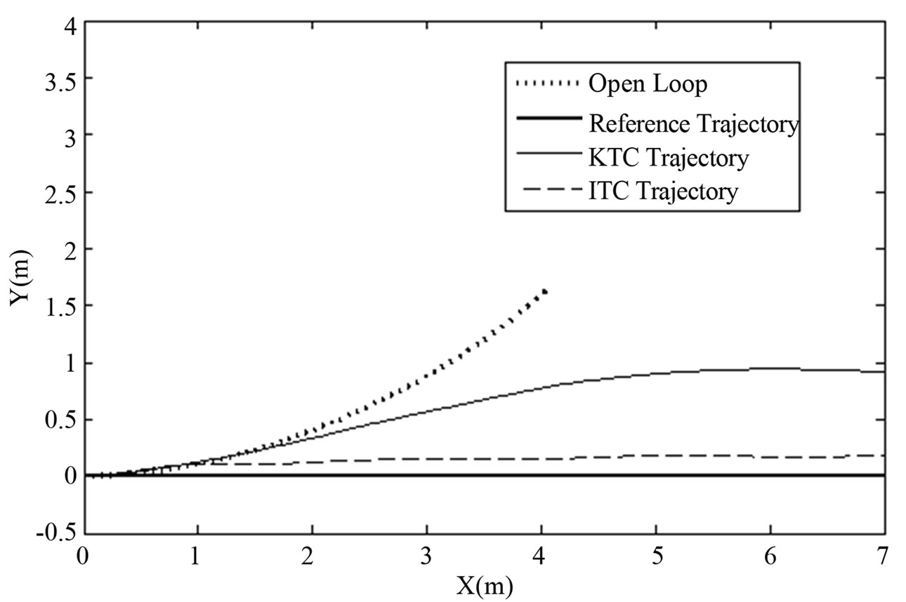
Figure 8. Linear Trajectory Tracking with the Rear Driven Wheelchair.
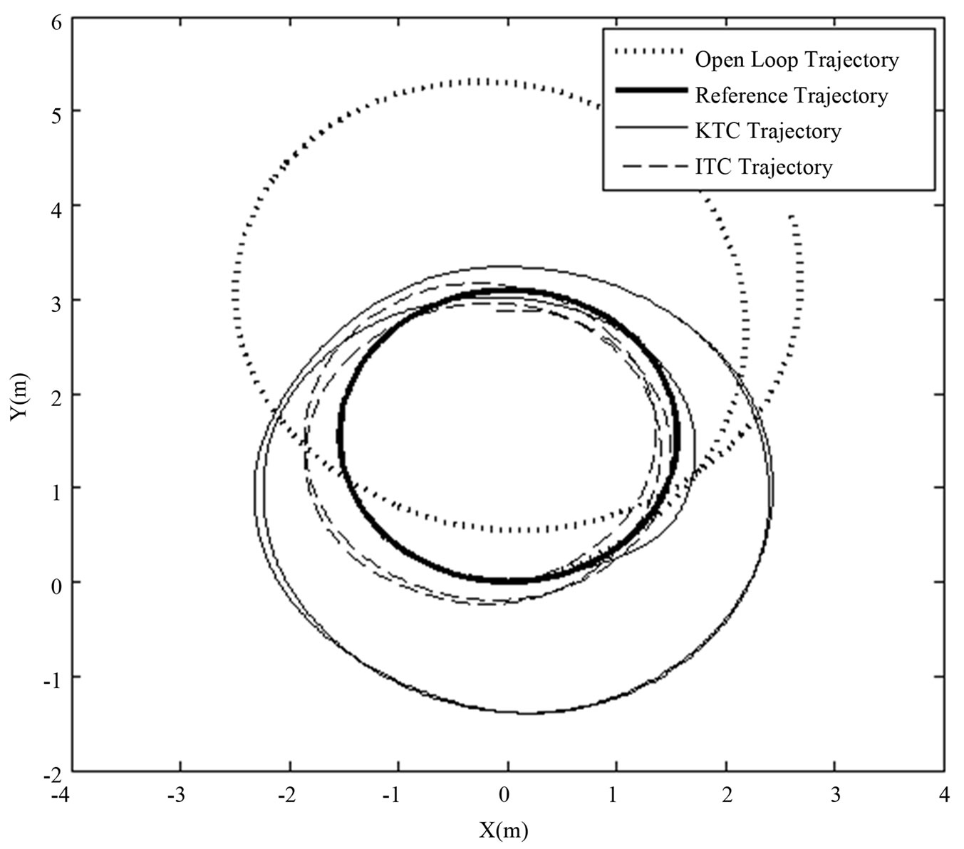
Figure 9. Curvilinear Trajectory Tracking with the Rear Driven Wheelchair.
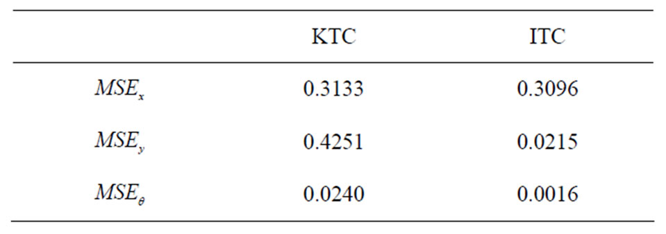
Table 3. Tracking Mean-Square Errors with Rectilinear Trajectories.
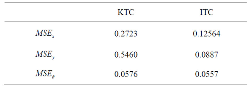
Table 4. Tracking Mean-Square Errors with Curvilinear Trajectories.
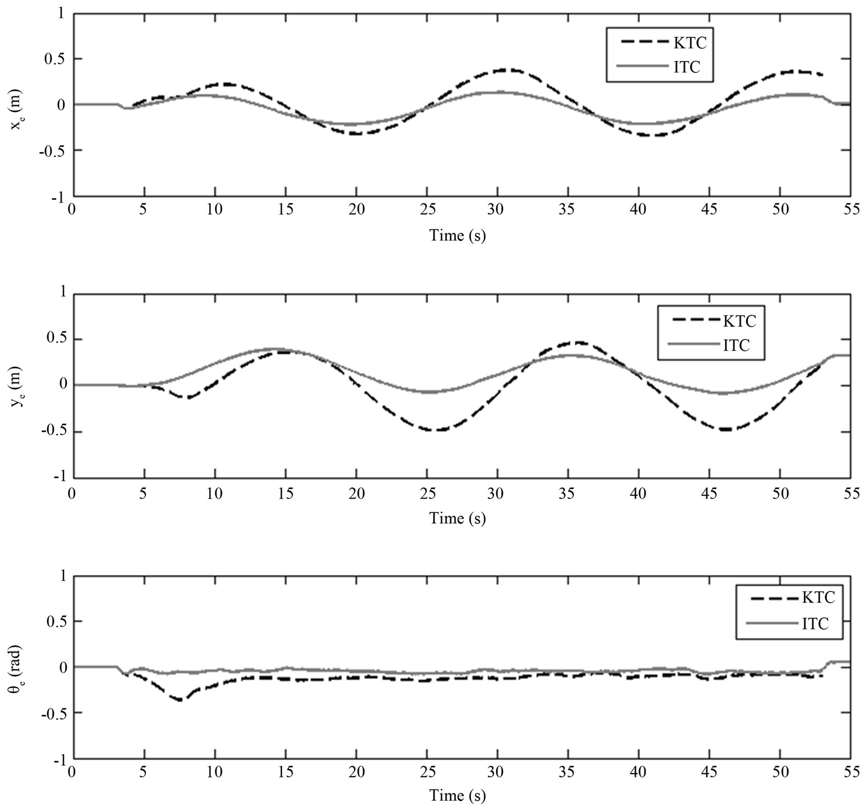
Figure 10. Curvilinear Trajectory Tracking Error with the Rear Driven Wheelchair.
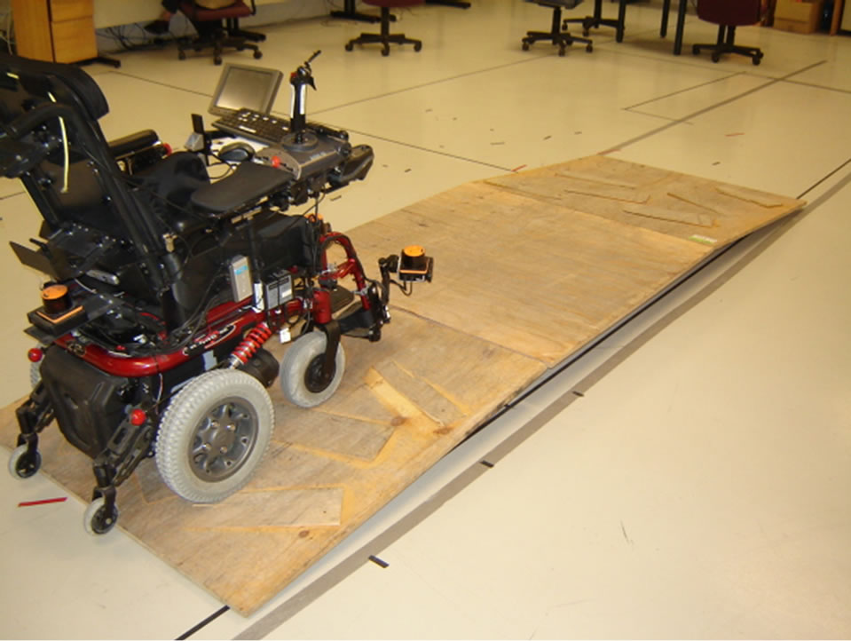
Figure 11. Navigating on inclined surfaces.
rolling horizontally for 3.75 m (see Figure 11). Disturbances come from the front caster orientations, the 2.5 cm denivellation, the two inclines and the uneven navigation surfaces.
We were unable to perform this test with the KTC approach. Indeed, due to the bias velocities and due to insufficient compensation of perturbations, the wheelchair was unable to remain on the first incline. Figure 12 presents the result obtained with the ITC approach only. The platform successfully completed the test with a maximum deviation of on the Y-axis despite disturbances, with the following tracking mean-square errors:
 ,
,  and
and .
.
5. Conclusion
The design of adaptive nonlinear kinematic and dynamic controllers have been presented. The kinematic controller takes into account the positional difference between the platform rotation center and its gravity center. Furthermore, it accounts for bias velocities induced by uncompensated actuator dynamics. For smooth and bounded velocities, the global stability and the convergence of the
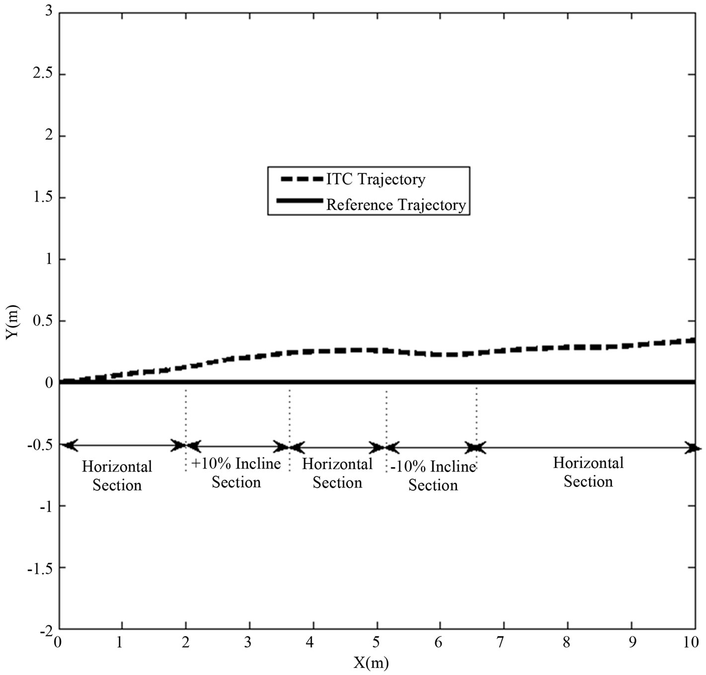
Figure 12. Trajectory Tracking on Inclined Surfaces.
kinematic controller have been derived using Lyapunov stability theory and the conditions for the local stability and convergence were provided. The dynamic controller, based on the reference model approach, has the desirable property of not requiring the knowledge of the platform physical parameters (mass and inertia). Its stability has been established through Barbalat’s lemma. The controller’s design approach presented in this paper greatly increases the trajectory tracking performance. Simulation as well as comparative experiments performed on a rear driven wheelchair have demonstrated the stability and the effectiveness of the proposed approach.
REFERENCES
- M. Deng, A. Inoue, K. Sekiguchi and L. Jiang, “TwoWheeled Mobile Robot Motion Control in Dynamic Environments,” Robotics and Computer-Integrated Manufacturing, Vol. 26, No. 3, 2010, pp. 268-272. http://dx.doi.org/10.1016/j.rcim.2009.11.005
- W. Yu, O. Y. Chuy Jr., E. G. Collins Jr. and P. Hollis, “Analysis and Experimental Verification for Dynamic Modeling of a Skid-Steered Wheeled Vehicle,” IEEE Transactions on Robotics, Vol. 26, No. 2, 2010, pp. 340- 353. http://dx.doi.org/10.1109/TRO.2010.2042540
- D.-E. Ameddah and T. Benmokrane, “A Comparison of a Classical Pid and Sliding Mode: Traction Control for Fast Wheeled Mobile Robot,” International Journal of Automation and Control, Vol. 4, No. 1, 2010, pp. 65-83. http://dx.doi.org/10.1504/IJAAC.2010.029839
- H. Wang and G. Li, “Motion Control and Trajectory Tracking Control for a Mobile Robot via Disturbance Observer,” WSEAS Transactions on Systems, Vol. 9, No. 1, 2010, pp. 31-41.
- M. K. Bugeja, S. G. Fabri, and L. Camilleri, “Dual Adaptive Dynamic Control of Mobile Robots Using Neural Networks,” IEEE Transactions on Systems, Man, and Cybernetics, Part B: Cybernetics, Vol. 39, No. 1, 2009, pp. 129-141. http://dx.doi.org/10.1109/TSMCB.2008.2002851
- R. W. Brocket, “Asymptotic Stability and Feedback Stabilization,” In: R. W. Brockett, R. S. Millman and H. J. Sussmann, eds., Differential Geometric Control Theory, Birkhauser, Boston, 1983, pp. 181-208.
- E. Noohi, S. S. Mahdavi, A. Baghani and M. N. Ahmadabadi, “Wheel-Based Climbing Robot: Modeling and Control,” Advanced Robotics, Vol. 24, No. 8-9, 2010, pp. 1313-1343. http://dx.doi.org/10.1163/016918610X501453
- Y. Kanayama, Y. Kimura, F. Miyazaki and T. Noguchi, “A Stable Tracking Control Method for a Non-Holonomic Mobile Robot,” Proceedings of IEEE/RSJ International Workshop on Intelligent Robots and Systems ’91. Intelligence for Mechanical Systems, Osaka, 3-5 November 1991, pp. 1236-1241.
- J. L. Avendano-Juarez, V. M. Hernandez-Guzman and R. Silva-Ortigoza, “Velocity and Current Inner Loops in a Wheeled Mobile Robot,” Advanced Robotics, Vol. 24, No. 8-9, 2010, pp. 1385-1404. http://dx.doi.org/10.1163/016918610X501480
- A. Astolfi, “Exponential Stabilization of Nonholonomic Systems via Discontinuous Control,” Journal of Dynamic Systems, Measurement, and Control, Vol. 121, 1999, pp. 121-126. http://dx.doi.org/10.1115/1.2802429
- Z.-G. Hou, A.-M. Zou, L. Cheng and M. Tan, “Adaptive Control of an Electrically Driven Nonholonomic Mobile Robot via Backstepping and Fuzzy Approach,” IEEE Transactions on Control Systems Technology, Vol. 17, No. 4, 2009, pp. 803-815. http://dx.doi.org/10.1109/TCST.2009.2012516
- R. C. Luo, T. M. Chen, C.-Y. Hu and Z. H. Hsiao, “Adaptive Intelligent Assistance Control of Electrical Wheelchairs by Grey-Fuzzy Decision-Making Algorithm,” Proceedings of IEEE International Conference on Robotics and Automation, Vol. 3, 1999, pp. 2014-2019.
- B. S. Park, S. J. Yoo, J. B. Park and Y. H. Choi, “Adaptive Neural Sliding Mode Control of Nonholonomic Wheeled Mobile Robots with Model Uncertainty,” IEEE Transactions on Control Systems Technology, Vol. 17, No. 1, 2009, pp. 207-214. http://dx.doi.org/10.1109/TCST.2008.922584
- A. Venelinov Topalov, J.-H. Kim and T. Proychev, “Fuzzy-Net Control of Non-Holonomic Mobile Robot Using Evolutionary Feedback-Error-Learning,” Robotics and Autonomous Systems, Vol. 23, No. 3, 1998, pp. 187- 200. http://dx.doi.org/10.1016/S0921-8890(98)80013-4
- J. Wang, Z. Qu, M. Obeng and X. Wu, “Approximation Based Adaptive Tracking Control of Uncertain Nonholonomic Mechanical Systems,” Control and Intelligent Systems, Vol. 37, No. 4, 2009, pp. 204-211.
- M. Egerstedt, X. Hu and A. Stotsky, “Control of Mobile Platforms Using a Virtual Vehicle Approach,” IEEE Transactions on Automatic Control, Vol. 46, No. 11, 2001, pp. 1777-1782. http://dx.doi.org/10.1109/9.964690
- J. Chang and Q.-X. Meng, “Stabilization Control of Nonholonomic Wheeled Mobile Service Robots,” Key Engineering Materials, Vol. 419-420, 2010, pp. 593-596. http://dx.doi.org/10.4028/www.scientific.net/KEM.419-420.593
- R. Mukherjee, D. Chen and G. Song, “Feedback Control Strategies for a Nonholonomic Mobile Robot Using a Nonlinear Oscillator,” Journal of Robotic Systems, Vol. 16, No. 4, 1999, pp. 237-248. http://dx.doi.org/10.1002/(SICI)1097-4563(199904)16:4<237::AID-ROB4>3.0.CO;2-F
- C. Samson, “Velocity and Torque Feedback Control of a Nonholonomic Cart,” Lecture Notes in Control and Information Sciences, Vol. 162, 1991, pp. 125-151. http://dx.doi.org/10.1007/BFb0039269
- K. Tsuchiya, T. Urakubo and K. Tsujita, “Motion Control of a Nonholonomic System Based on the Lyapunov Control Method,” Journal of Guidance, Control, and Dynamics, Vol. 25, No. 2, 2002, pp. 285-290. http://dx.doi.org/10.2514/2.4880
- W. Oelen, H. Berghuis, H. Nijmeijer and C. C. de Wit, “Hybrid Stabilizing Control on a Real Mobile Robot,” IEEE Robotics and Automation Magazine, Vol. 2, No. 2, 1995, pp. 16-23. http://dx.doi.org/10.1109/100.392415
- T. Urakubo, K. Tsuchiya and K. Tsujita, “Motion Control of a Two-Wheeled Mobile Robot,” Advanced Robotics, Vol. 15, No. 7, 2001, pp. 711-728. http://dx.doi.org/10.1163/15685530152744581
- C.-L. Hwang, “A Novel Takagi-Sugeno-Based Robust Adaptive Fuzzy Sliding-Mode Controller,” IEEE Transactions on Fuzzy Systems, Vol. 12, No. 5, 2004, pp. 676- 687. http://dx.doi.org/10.1109/TFUZZ.2004.834811
- A. Rojko and K. Jezernik, “Sliding-Mode Motion Controller with Adaptive Fuzzy Disturbance Estimation,” IEEE Transactions on Industrial Electronics, Vol. 51, No. 5, 2004, pp. 963-971. http://dx.doi.org/10.1109/TIE.2004.834945
- A. Fel’Dbaum, “Application of Theory of Statistical Solutions to Open and Closed-Loop Automatic Control Systems,” Engineering Cybernetics, No. 1, 1963, pp. 1-12.
- Y. Ou and Y. Xu, “Gyroscopically Stabilized Robot: Balance and Tracking,” International Journal of Advanced Robotic Systems, Vol. 1, No. 1, 2004, pp. 23-32.
- F. Mnif and A. Yahmadi, “Recursive Backstepping Stabilization of a Wheeled Mobile Robot,” Vol. 219, No. 6, 2005, pp. 419-429.
- R.-J. Wai and C.-M. Liu, “Design of Dynamic Petri Recurrent Fuzzy Neural Network and Its Application to Path-Tracking Control of Nonholonomic Mobile Robot,” IEEE Transactions on Industrial Electronics, Vol. 56, No. 7, 2009, pp. 2667-2683. http://dx.doi.org/10.1109/TIE.2009.2020077
- R. Fierro and F. Lewis, “Control of a Nonholonomic Mobile Robot: Backstepping Kinematics into Dynamics,” Proceedings of the 34th IEEE Conference on Decision and Control, Vol. 4, 1995, pp. 3805 -3810.
- S. Kelouwani, C. Ouellette and P. Cohen, “Adaptive Nonlinear Controller Design for Differential-Drive Mobile Platforms,” 2010 IEEE/ASME International Conference on Advanced Intelligent Mechatronics, 6-9 July 2010, pp. 1238-1244.
- J. Craig, Introduction to Robotics: Mechanics and Control. 1em plus 0.5em minus 0.4em Addison-Wesley, 1989.
- R. DeSantis, “Dynamique des Systèmes Mécaniques Sous Contraintes Holonomes et Non Holonomes,”1em plus 0.5em minus 0.4em École Polytechnique de Montréal, 1989.
- S. Sastry and M. Bodson, “Adaptive Control: Stability, Convergence, and Robustness,” 1em plus 0.5em minus 0.4em Prentice-Hall Advanced Reference Series (Engineering), 1994.
- S. K. Vincent Zalzal, R. Gava and P. Cohen, “Acropolis: A Fast Prototyping Robotic Application,” International Journal of Advanced Robotic Systems, Vol. 6, No. 1, 2009, pp. 1-6.
- L. Montesano, M. Diaz, S. Bhaskar and J. Minguez, “Towards an Intelligent Wheelchair System for Users with Cerebral Palsy,” IEEE Transactions on Neural Systems and Rehabilitation Engineering, Vol. 18, No. 2, 2010, pp. 193-202. http://dx.doi.org/10.1109/TNSRE.2009.2039592
- M. Elarbi-Boudihir and K. Al-Shalfan, “Adaptable Intelligent Robotic Wheelchair for Severely Disabled People,” Journal of Digital Information Management, Vol. 7, No. 4, 2009, pp. 252-260.
Appendices
1. Derivative of the Configuration Error
The configuration error derivative is given by:
Proposition 5.1
 (26)
(26)
Proof 1
Since 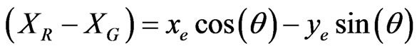 and
and 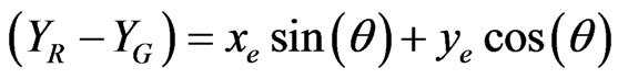 , we obtained:

From expression (0.11), we got  and
and  becomes:
Substituting  by
by  and knowing that
 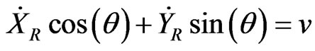 and
and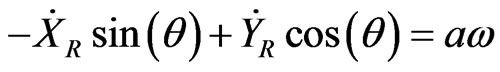 , we obtained:
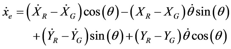
The expression of  is obtained as followed:
Following the same approach as that used for , we obtained:
Substituting  by
by  and since
 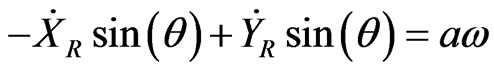 and
and 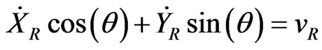 , we obtained:
From expression (10), it yields that:
2. Global Asymptotical Convergence of the Kinematic Controller
Proposition 5.1 The errors  converge asymptotically toward
 .
.
Proof 2 Consider the Lyapunov function candidate represented by expression (0.27):
 (27)
(27)
Its derivative is given by:
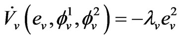
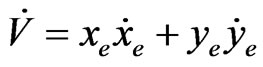 (28)
(28)
From expression (13), we got:
 (29)
(29)
Substituting  and
and  in (12) by their expression (29) we obtained:
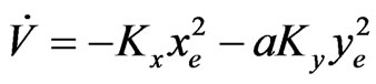 (30)
(30)
Since  and
and ,
,  is Lyapunov function and
  converge asymptotically to
 .
.
3. Local Asymptotical Convergence of the Kinematic Controller
Proposition 5.1 The system using control laws (13) is locally asymptotically stable, if the reference velocity ,
,  and
and .
.
Proof 3 Substituting  and
and  with (29) in (12) and linearizing the result, we obtain the following approximation of the configuration error:
 (31)
(31)
The eigenvalues of the matrix are the roots of the function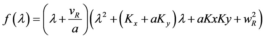 .
.
Since ,
,  ,
,  and
and , all the roots of
  have negative real part. Hence, the configuration error
  converge locally to
 .
.
4. Asymptotical Convergence of the Dynamic Controller
Proposition 5.1 If the control law (15) is used with the adaptive laws (17) and (18), then the tracking error  converges asymptotically to 0 under the following condition:
  and
and  are bounded.
Proof 4 The derivative  of the tracking error
  is given by
where  and
and .
.
According to Shankar [33], a Lyapunov candidate function is represented by the following expression:
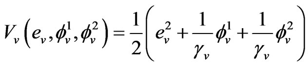
where the constant  is chosen in order to meet a predefined dynamic performance.
Clearly, 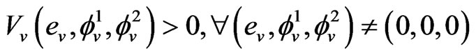 and
and  when
when ,
,  and
and  .
.
The derivative expression of the proposed Lyapunov candidate function is given by:
Substituting  and
and  by their expressions (refer to (17) and (18)) yields:
Since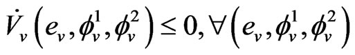 ,
,  are bounded. Hence,
  and
and  are bounded. Since
  and
and  are bounded,
  is also bounded according to equation (17), therefore,
  is bounded. Moreover, from equation (17),
  can be chosen in order to let
 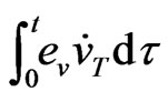 as small as possible. A similar analysis shows that
  is also bounded.
From equation (18), we can state that  is bounded because we have shown that
  and
and  are bounded. With an appropriate selection of
 ,
,  can be as small as possible.
Since vT and ωT are bounded and since  can be as small as possible, the global tracking error
 ,
,  and
and  are also bounded according to equation (13). Moreover these errors can be as small as possible.
To demonstrate that  converge asymptotically to 0, let consider the second derivative of
 :
:

Since we have previously shown that ,
,  ,
,  ,
,  and
and  are bounded, then
  is also bounded.
According to Barbalat’s lemma, since  and since
  is bounded
 , the tracking error asymptotically converges to 0 if the proposed update laws (17) and (18) are used.
NOTES
*This work has been supported by the Natural Science and Engineering Research Council of Canada (Grant No CRD 349481-06 Scholarship No BESC D3-348674-2007). The collaboration and support of Robovic Inc., Sunrise Medical Canada are as well gratefully acknowledged. The authors wish to thank Hai Nguyen, Patrice Boucher, Vincent Zalzal, Raphael Gava and Alexandre Fortin from the Perception and Robotics Laboratory of Ecole Polytechnique for their contributions on implementation and testing.