Wireless Engineering and Technology
Vol.4 No.2(2013), Article ID:29811,7 pages DOI:10.4236/wet.2013.42018
UWB System Based on the Modified Gegenbauer Function in MISO Channel
![]()
Université Lille Nord de France, Lille, France.
Email: fouzia.boukour@ifsttar.fr
Copyright © 2013 A. Okassa M’foubat et al. This is an open access article distributed under the Creative Commons Attribution License, which permits unrestricted use, distribution, and reproduction in any medium, provided the original work is properly cited.
Received August 31st, 2012; revised November 12th, 2012; accepted November 27th, 2012
Keywords: UWB; MISO Channel; Rake Receiver; LMMSE; Modified Gegenbauer Function
ABSTRACT
In this paper, we propose a new multi-user Rake receiver, based on the interference mutualization with a matrix representation for Multiple Input Single Output MISO channel. The proposed system used the Modified Gegenbauer functions in order to generate the signal and to ensure the multi users transmission system. The new proposed receiver allows, using the temporal and special diversity, to avoid the interferences between symbols and to improve the system performances in terms of Bit Error Rate BER and interferences between users with a low algorithm complexity. The proposed solution is based on the classical Rake receiver associated with the equalizer receiver. In order to adapt the Rake approach, in single detection case and in multi users Ultra Wide Band environment, we propose a multi-user Rake receiver using the matrix form. Our proposed system is evaluated in terms of channel effects and multi users’ interferences.
1. Introduction
In recent years a considerable interest arose in ultrawideband (UWB) communication systems, due to their appealing features and release of the spectral mask from the Federal Communications Commission (FCC) [1]. This technology has many potential advantages such as high data rate, low probability of interception and detection, low complexity, low cost, reduced average power consumption, weak sensitivity to the near-far problem and immunity to interferences [2-4]. The UWB system communicates using short-duration pulses lower than nanosecond. Several waveforms can be used, like Gaussian pulses, monocycle pulses or waveforms based on orthogonal polynomials like Hermite and Gegenbauer functions [5-7]. The orthogonal functions allow, without orthognals code used in classical multi users systems, to share the channel propagation between the users. The previous works have shown that the Modified Gegenbauer functions or MGF give good results in terms of BER in the case of Additive White Gaussian Noise (AWGN) channel [8]. In order to introduce the multi channel effects, the modified Saleh-Valenzuela (S-V) model was adopted in 2003 as UWB channel reference model by the IEEE 802.15.3a [9]. The modelling of UWB channels is based on the measurement of indoor propagation environment, as the main commercial applications will be indoor communications. The main distinguishing features of UWB channel propagation are its extremely multipath-rich profile and non-Rayleigh fading amplitude characteristics. The UWB channel is characterised by the impluse response with high path number and delays between 50 to 150 ns [10].
For high data rate, the superposition of symbols in the receiver destroys the signal and generates intersymbol interferences. However, the Rake receivers, using the spatial diversity (antenna) and temporal diversity improve the receiver performance and maximise the signal to noise ratio at the receiver output.
Several type of Rake receivers have been proposed such as the Arake receiver that combines all the signal paths [11-13]. This receiver is not easy to implement because UWB channel is characterised by a large number of multipath.
However a feasible implementation can be obtained using a selective Rake (Srake), which combines the multipath components with a higher power. Maximal Ratio Combining MRC receiver Rake uses the path with higher signal noise ratio SNR [14]. This receiver is optimal in the AWGN channel, without multi users interference and without interference symbols. For multi users interferences and symbol interferences cases, others receivers are proposed to improve the BER values but with higher algorithm complexity [15,16].
In our approach, in order to have a low cost solution, we propose a multi-user Rake receiver in Multiple input Single Output MISO channel based on the matrix representation. The new receiver has a computational complexity equal to the product of the user numbers M and the symbol numbers Q transmitted in a packet of data frame. In this case, the complexity is lower compared to the others receivers cases.
The results obtained and compared to different receivers show that our approach improves the performances in terms of BER, gives better performances with a lower complexity algorithm.
This paper is organized as follows. In the first section, we describe the UWB system and structure of the MISO channel. The second section highlights the main drawbacks of using single detection receivers based on Rake receivers MRC in a multi user. The third section presents our approach proposed and in the fourth section we give simulation results and discussions. At the end, a conclusion is drawn with prospects.
2. The Proposed UWB System
In order to exploit the diversity benefits, the receiver must be able to combine different transmitted signals. The presented methods assume that different signals to be combined are received through different branches [17]. In case, the generated signals are the packets Q, with equiprobility bits modulated using the Binary Phase Shift Keying modulation (BPSK). If we consider Q packet of data frame, the transmitted signal for user k is given by the following Equation:
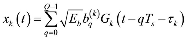 (1)
(1)
where  is the bit energy and
  is the symbol period.
The zero mean i.i.d data symbol  are passed through a unit energy pulse shaping
  includes the effects of transmit antenna. In this equation, each Gegenbauer order is assigned to each active user. The used pulses
  are defined by the recurrence relation:
 (2)
(2)
where  is the time in nanosecond,
  the order of the Gegenbauer function and
  is the parameter defining the Gegenbauer polynomials family. The results in [17] show that
  gives the best performance of UWB system. The orthogonality condition is satisfied for all
 (3)
(3)
The Gegenbauer polynomials may be used in UWB systems to construct MGF pulses with narrow widths. For this purpose, they are multiplied by the square root the weight function . These functions, that satisfy the Equation (3), are given by the following formula:
 (4)
(4)
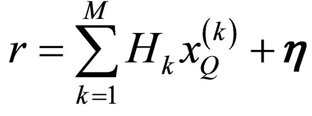
We consider a MISO channel with each transmitted (antenna) is composed of a MGF pulse as shown in Figure 1, the signal  through the channel propagation. In the output receiver, the signal received by the station is the sum of signal of all users can be written:
 (5)
(5)
where  is the Additive White Gaussian Noise AWGN with zero mean and variance
 ;
;  is the impulse response associated with the kth user.
The stochastic channel models, used to evaluate the physical layer of UWB, are adopted by the committee 802.15.3a especially for the intra-building environment, short-range (up to 10 m) for high date speed communications (>100 Mbit/s). These models are defined by an impulse response and given in the following equation:
 (6)
(6)
where  is the gain coefficient of the ith ray within the lth cluster.
  is the delay of lth cluster for desired user.
  is the delay of the ray relative to the cluster arrival time
  of the desired user’s.
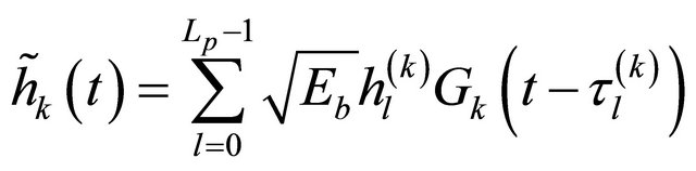
  represents the log-normal shadowing; L and P indicate respectively the number of resolvable path and the number of rays of each cluster. To simplify the analysis, we can write the impulse response in another form as:

Figure 1. Illustration of model.
 (7)
(7)
where  is the total number of rays,
  and
and  are the gain and delay introduced by the lth ray. As the number of signal sample
  is
is  is the sample of pulse
 ; then the convolution operation between the signal
  and the impulse response
 , therefore the number of signal
 , signal sample is
 : assuming that j is the desired user and
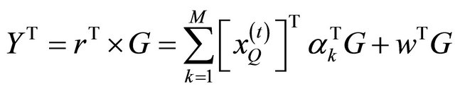
  is the symbol of the j desired user. The received signal given by 5 can be written by the following equation:
 (8)
(8)
with
 (9)
(9)
In this equation there are three different terms. The first term corresponds to the useful signal of the desired user, the second term is the symbol interference. This second term interact with the useful signal when the total duration of the response channel denoted  is higher than the symbol duration
 . The third term corresponds to the multi-user interference.
3. Single Detector Receivers: Case of Rake Receivers
Due to the fact that impulse responses have a large number of multiple paths, using Rake receiver [18] method used in several studies to exploit the diversity of impulse and to maximize the energy available for the receiver. By identifying  the correlation output of branch i, the output of the receiver, after single-user combination in the case of Rake, is given by the following formula:

where  is the number of receiver branch and
  is the weight assigned to the branch i, regardless the combination method. For the branch i, with the delay
 , the output of the correlator or conventional receiver is given by :
 (10)
(10)
In the multi user case, where each user transmits in a channel different from its neighbor as expressed by Equation (8), the choice of weights assigned  for the branch i, as proposed in several studies, cannot be efficient for estimating the symbols, even though no actual interference between symbols occurs. If we adopt the all Rake (Arake) with MRC and when the channel is knownthe gains combinations
are identical to the channel gain with
 . In this case
for  and
and .
.
4. Novel Approach Proposed
In this section, to improve the reception performances, we propose a multi-user Rake receiver matrix representation using MGF functions. The idea of this approach is to mutualise different interferences as seen in Equation (8), to constitute only a single type of interference. In this case, interference cancellation can be combined easily. So, the signal received from the user k illustrated by Figure 1 can be formulated as following:
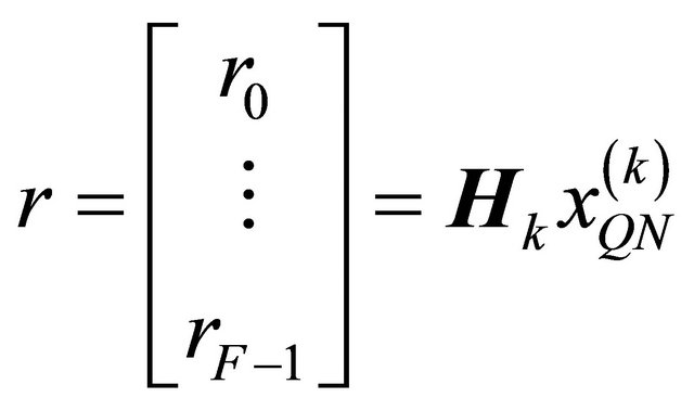 (11)
(11)
where  is the transmitted waveform;
  is a channel matrix of dimension
 ;
;  represents spread data and therefore, can be expressed as:
 (12)
(12)
Here  is a column vector which represents the symbols transmitted by the user
  with the dimension
 ;
;  denotes a column vector of the modified Gegenbauer function sampled by
  factor;
  is the identity matrix of size
 ; the operand means the Kronecker product and the operand
  is a column vector which allows the concatenation of the column vectors of a matrix. The channel matrix
  is expressed by:

 (13)
(13)
We can note that, in  element
  for
for . The matrix channel
  is lower triangular due to the causal nature of
 . For the purposes of Arake receiver, the channel gain vector must be
  . Assuming
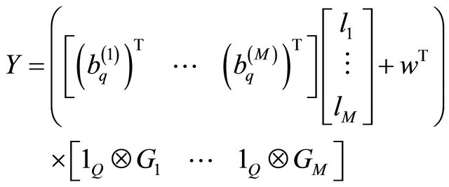
  active users, the received signal is given by this formula:
 (14)
(14)
where  is a column vector corresponding to the Gaussian noise with zero mean and variance
 . Similarly to the Rake receiver single detection, here we choose gains of each branch as vector
 . Thus the channel matrix Arake
  can be decomposed into a sum of the various paths as following:

 (15)
(15)
where  is a shift matrix expressed by
 (16)
(16)
To extract the symbols, observed variable  is despread by applying a matrix correlation
 . That gives
 (17)
(17)
If we set
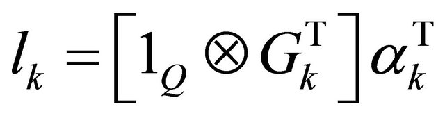 (18)
(18)
It combines the different  in a matrix constituted of elements
  of dimension
 . So Equation (17) becomes:
 (19)
(19)
Let us consider
 (20)
(20)
where  is mutualisation of different interferences matrix. By substituting the channel matrix Arake
  by the expression of Equation (15), development of the square matrix
  whose dimension is
  could be written as following:
 (21)
(21)
where  and
and  represent respectively the coefficient matrix of the multipath channel and the index of relative delay multipath; the matrix
  and
and  give respectively the correlation matrix and matrix of code shifted by a number of lines
  upwards. The matrix
  and
and  are defined as following:
 (22)
(22)
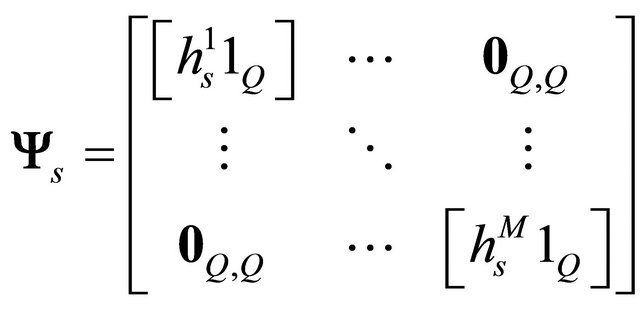 (23)
(23)
here  is the zero matrix whose size is
 . In this configuration, the equation of the variable decision is encapsulated:
 (24)
(24)
where 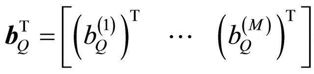 are random vector of parameters whose realization is to be estimated and has mean zero and covariance matrix is
  of the dimension symbols
 . Thus, the new variance of noise denoted equal to
 . To restore the transmitted symbols, the optimal data estimation
  should resolve the approach to the problem of least squares assuming
  such as
 (25)
(25)
By solving Equation (8), data estimation is obtained by
 (26)
(26)
With  the pseudo inverse matrix.
This algorithm is referred to using the acronym Rake-LS (Rake least squares). Unfortunately the optimal solution in the least-squares approach is obtained without the Gaussian noise [19-22]. Forcing the interference zeros pooled significantly amplify the noise. The LMMSE approach allows taking into account the noise and the correlation factor in the variable decision, is obtained by minimizing the following equation:
 (27)
(27)
where  means the mathematical Esperance. The solution of Equation (27) using [19] gives:
 (28)
(28)
This algorithm is referred to using the acronym RakeLMMSE [23,24]. In the case of Single Input Single Output SISO channel where all users transmit on a single channel  only the matrix
  is modified and then, becomes:
 (29)
(29)
In the presence of multi users interference and lack of interference intersymbol, the proposed approach reduces the correlation matrix to the value  and consequently, the complexity of design loads is reduced and thus the matrix
  has the dimension
 .
.
5. Simulation Results and Discussions
In this section, we discuss simulation results of ultra wideband system using stochastic channel models adopted by the committee IEEE 802.15.3a. To analyze the results, we studied the case of using the four first orders of modified Gegenbauer functions, where each waveform with duration of 2 ns is assigned to each user. The signal waveforms are sampled at the period . The simulations are performed on Matlab using the Monte Carlo method. Two antenna configurations are analyzed, the case of transmission in SISO channel and MISO channel. Four types of channels IEEE 802.13a noted CM1 to CM4 are used in our simulation. Here we took a frame of data closed by four symbols, i.e. the transmission rate at 8 ns.
In the simulations, the following Figure 2 shows that, according to a user associated with each order of the Gegenbauer polynomials, performances may vary depending on the desired user. By choosing the first 4 orders (1 2 3 4), where order 1 and order 2 is named respectively user N#1 and user N#2. The user N#2 gives good performances compared to the user N#1, and this, whatever the type of receiver used. Also the configuration of the antennas has an impact on the receivers’ performances. In this Figure 2, we can see that the proposed approach gives better performances compared than conventional and Arake receivers. Also the performances of
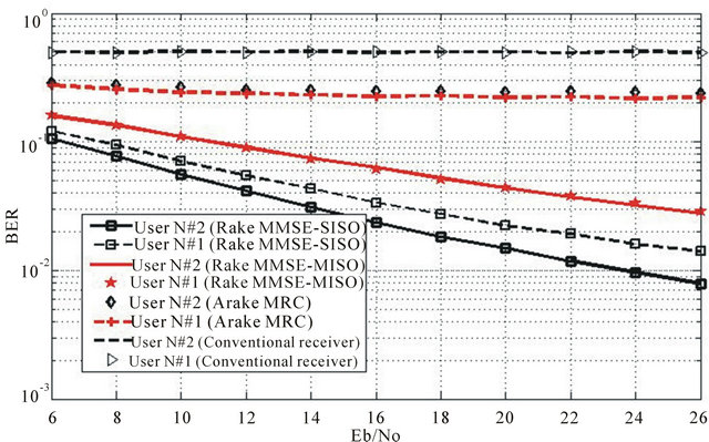
Figure 2. BER versus Eb/No in case of CM1 environment with respectively waveforms functions orders (1, 2, 3, 4).
Rake LMMSE are significantly better than those obtained with the Rake-LS method. Figure 3 shows the proposed approach performances, while increasing duration of a symbol. We note that the performances degrade as a function of the reduction of the symbol duration.
The Figure 4 shows the impact of channel types on the algorithm performances. It is observed that the proposed approach is more resistant to channels degradation, compared to the conventional and Arake receivers. Finally, in the absence of the transmission channel, the proposed receiver performances are close to the optimal solution, compared to the conventional receiver. Despite the presence of interferences and lack of interference between symbols, the proposed approach gives performances close to optimal results, i.e. in the case of a threshold in a user environment, without interference of intersymbols. This is illustrated on Figure 5.
6. Conclusion
In this paper, we proposed a receiver that combines all interferences in a MISO channel using the modified Gegenbauer polynomials. A novel proposed approach based on the matrix representation is given. The simula-
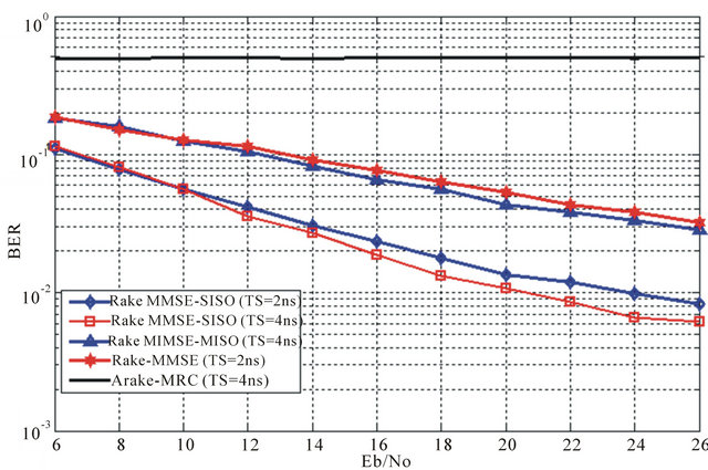
Figure 3. BER versus SNR for 4 symbols in case of CM1 environment with respectively waveforms orders (1, 2, 3, 4).
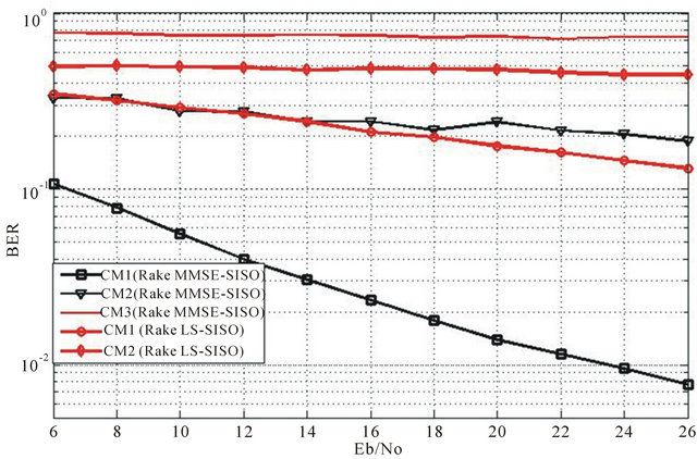
Figure 4. Receiver performances according to type of environment (CM1 to CM3) under user N#2.

Figure 5. Performances in the presence and absence of the channel under CM1 environment.
tions carried out, show that our approach gives high performances compared to a conventional or ARAKE receivers. Using this new approach, we can achieve a trade-off between performance in terms of bit error rate and computational complexity. Our approach offers a high performance system in terms of data rate and bit error rate with a low cost. In the future work, we will apply these studies on others channel type such as the IEEE 802.15.4a models. We will validate these theoretical and simulation results by tests in real environments.
REFERENCES
- FCC Notice of Proposed Rule Making, “Revision of Part 15 of the Commission’s Rules Regarding Ultra Wideband Transmission System,” ET-Docket 98-153.
- M.-G. Benedetto and B. R. Vojcic, “Ultra Wide Band (UWB) Wireless Communications: A Tutorial,” Journal of Communication and Networks, Special Issue on UltraWideband Communications, Vol. 5, No. 4, 2003, pp. 290- 302.
- J. Balakrishnan, A. Batra and A. Dabak, “A Multi-Band OFDM System for UWB Communication,” 2003 IEEE Conference on Ultra Wideband Systems and Technologies, Dallas, 16-19 November 2003, pp. 354-358.
- Yang and G. B. Gianniakis, “Ultra Wideband Communications: An Idea Whose Time Has Come,” IEEE Signal Processing Magazine, Vol. 21, No. 6, 2004, pp. 26-24. doi:10.1109/MSP.2004.1359140
- G. T. F. de Abreu, C. J. Mitchell and R. Kohno, “On the Design of Orthogonal Pulse-Shape Modulation for UWB Systems Using Hermite Pulses,” Journal of Communications and Networks, Vol. 5, No. 4, 2003, pp. 328-343.
- B. M. Lachlan, M. Ghavami and R. Kohno, “Multiple Pulse Generator for Ultra-Wideband Communication Using Hermite Polynomial Based Orthogonal Pulses,” IEEE Conference on Ultra Wideband Systems and Technology, 2002, pp. 47-51.
- C.-Y. Tsai and S.-K. Jeng, “Design of a Legendre-Polynomial-Based Orthogonal Pulse Generator for Ultra-Wideband Communications,” Antennas and Propagation Society International Symposium, Vol. 2B, 2005, pp. 680-683.
- F. Elbahhar, A. Rivenq-Menhaj, J. M. Rouvaen, M. Heddebaut and T. Boukour, “Comparison between DS-CDMA and Modified Gegenbauer Functions for a Multi-User Communication Ultra Wide Band System,” IEEE Proceedings Communications, Vol. 152, 2005, pp. 1021-1028. doi:10.1049/ip-com:20045236
- A. A. Saleh and R. A. Valenzuela, “A Statistical Model for Indoor Multipath Propagation,” IEEE Journal on Selected Areas in Communications, Vol. SAC-5, No. 2, 1987, pp. 128-137. doi:10.1109/JSAC.1987.1146527
- P. Pagani, P. Pajusco and S. Voinot, “A Study of the Ultra-Wideband Indoor Channel: Propagation Experiment and Measurement Results,” COST273 TD(030)060, Barcelona, January 2003.
- J. Zhang, R. A. Kennedy and T. D. Abhayapala, “Conditions and Performance of Ideal RAKE Reception for Ultra-Wideband Signals in Log-Normal Fading Channels,” International Journal of Wireless Information Networks, Vol. 10, No. 4, 2003, pp. 193-200. doi:10.1023/B:IJWI.0000022050.22706.c4
- M. G. Khan, J. Nordberg, A. Mohammed and I. Claesson, “Performance Evaluation of Rake Receiver for UWB Systems Using Measured Channel Industrial Environments,” International Conference on Wireless Broadband on Ultra Wideband Systems, March 2006.
- Z. Xiao, L. Su, D. Jin and L. Zeng, “Performance Comparison of RAKE Receivers in SC-UWB Systems and DS-UWB Systems,” The Institute of Electronics, Information and Communication Engineers (IEICE) Transactions on Communications, Vol. E93-B, No. 4, 2010, pp. 1041-1044.
- A.-J. Liu, W. H. Xing and P. Ma, W.-B. Deng and B. Cao, “Performance of a Low Sampling Rate RAKE UWB Receiver in Multipath Environments,” International Workshop on Intelligent Systems and Applications, 2009.
- S. Verdu, “Multiuser Detection,” Cambridge University Press, Cambridge, 1998.
- Y. Li, A. F. Molisch and J. Zhang, “Channel Estimation and Signal Detection for UWB,” International Symposium on Wireless Personal Multimedia Communications (WPMC), October 2003.
- F. Elbahhar, A. Rivenq-Menhaj and J. M Rouvaen, “MultiUser Ultra Wide Band Communication System Based on Modified Gegenbauer and Hermite Functions,” Wireless Personal Communications (Kluwer), Vol. 34, No. 3, 2005, pp. 255-277. doi:10.1007/s11277-005-3922-2
- A. G. Kleini, D. R. Brown II, D. L. Goeckels and C. R. Johnson, “RAKE Reception for UWB Communication Systems with Intersymbol Interference,” 4th IEEE Workshop on Signal Processing Advances in Wireless Communications, 15-18 June 2003.
- J. G. Proakis, “Digital Communication,” 3rd Edition, MCGraw Hill International Editions, 1996.
- S. M. Kay, “Fundamentals of Statistical Signal Processing: Estimation Theory,” Prentice Hall, Upper Saddle River, 1996.
- J. G. Andrews, “Interference Cancellation for Cellular Systems: A Contemporary Overview,” IEEE Wireless Communications, Vol. 12, No. 2, 2005, pp. 19-29. doi:10.1109/MWC.2005.1421925
- A. Elabed, F. Elbahhar, Y. Elhillali, A. Rivenq and R. Elassali, “UWB Communication System Based on Bipolar PPM with Orthogonal Waveforms,” Wireless Engineering and Technology, Vol. 3, No. 3, 2012, pp. 181- 188. doi:10.4236/wet.2012.33026
- S. K. Sharma and S. N. Ahmadber, “Performance of SpaceTime Coded MMSE DFE for Wideband Code Division Multiple Access (WCDMA),” International Journal of Communications, Network and System Sciences, Vol. 2, No. 4, 2009, pp. 276-282. doi:10.4236/ijcns.2009.24030
- A. P. Doukeli, A. S. Lioumpas, G. K. Karagiannidis and A. V. Frangos, “Increasing the Efficient of Rake Receivers for Ultra Wide Band Applications,” Wireless Personal Communications, Vol. 62, No. 3, 2012, pp. 715-728. doi:10.1007/s11277-010-0090-9