Wireless Engineering and Technology
Vol. 4 No. 1 (2013) , Article ID: 27657 , 5 pages DOI:10.4236/wet.2013.41009
Design and Development of a 2 × 1 Array of Slotted Microstrip Line Fed Shorted Patch Antenna for DCS Mobile Communication System
![]()
1Department of PG Studies and Research in Applied Electronics, Gulbarga University, Gulbarga, India; 2University Science Instrumentation Centre, Gulbarga University, Gulbarga, India.
Email: gabidkar@rediffmail.com, vanirm12@rediffmail.com, prabhakar_hunagund@yahoo.co.in
Received May 4th, 2012; revised July 6th, 2012; accepted July 22nd, 2012
Keywords: Microstrip Antenna; Compact Antenna; Shorted Patch; Microstrip Line Fed
ABSTRACT
Compact microstrip antennas have recently received much attention due to the increasing demand of small antennas for personal communication equipment. The problem of achieving a wide impedance bandwidth for compact microstrip antennas is becoming an important topic in microstrip antenna design. In this paper the design and development of a 2 × 1 array of a low cost slotted microstrip line fed shorted patch antenna (MFSPA) has been presented. Both the shorted patch and microstrip line feed network have air substrate. The material cost is thus reduced to a minimum. The array consists of two adjacent patches fed, using a simple microstrip T network. The impedance bandwidth of nearly 40%, covering the bandwidth requirement of 1750 MHz band is obtained. Also the antenna exhibits dual band operation. The cross polarization radiation in H-Plane observed with a single element antenna has been reduced considerably with 2 × 1 array. A peak antenna gain of 9.2 dBi is obtained with a small variation of 0.8 dBi. From the results obtained it is clear that the antenna array studied has a low cost fabrication and is suitable for applications in DCS mobile communication base station.
1. Introduction
With the ever increasing demand for mobile communication and emergence of many systems, it is important to design broadband antennas to cover wide frequency range [1]. The design of an efficient wideband small size antenna for recent wireless applications is a major challenge. Microstrip patch antennas have found extensive application in wireless communication systems owing to their advantages such as low profile, conformability, low cost fabrication and ease of integration with feed networks [2]. However, conventional microstrip patch antennas suffer from narrow bandwidth. This poses design challenges for broad band applications [3]. There are well-known methods to increase the bandwidth of antennas including increase of the substrate thickness, the use of dielectric substrate of low dielectric constant, the use of various impedance matching and feeding techniques and use of slot antenna geometry [4,5].
In this paper, design, fabrication and study of the prototype of 2 × 1 array of low cost slotted microstrip line fed shorted patch antenna has been presented. The radiating patch is shorted to ground with the help of shorting plates of suitable width. Both microstrip feed line and shorted patch have air substrate of different heights. The single element MFSPA shown in Figure 1, offers a good broadside radiation pattern in the H-plane. But relatively greater cross polarization radiation is observed in the Hplane patterns. The Auto-CAD diagram of a single element antenna is as shown in Figure 2. An effort is made to reduce the cross polarization radiation by designing a 2 × 1 array of elements as shown in Figure 3. In the array configuration, two adjacent patches are fed, using a simple microstrip T network having half guided wavelength difference in length between its two output feed lines.
2. The Structure and Geometry of Single Element and 2 × 1 array of MFSPA
The artwork of the proposed antenna array is carried out by software, Auto-CAD 2004 for achieving better accuracy. The antenna is fabricated on a low cost glass epoxy substrate material of thickness h = 1.6 mm and dielectric constant 4.2. The radiating patch has a length L and width W. The patches are supported by plastic posts above the ground plane. The distance of the radiating patch to the ground plane is “h”. The radiating patch is short circuited to the ground plane by using identical shorting plates of width “d” placed at two ends of one of the patch’s radiating edges.
At the centre of the patch edge with shorting plates, a 50 ohm microstrip feed line is used to directly feed the radiating patch. The strip of the feed line has a width Wf and is connected to the radiating patch at the patch’s shorted edge by conducting strip of the same width Wf. The air substrates of shorted patch and feed line have heights “h” and “t” respectively. By selecting suitable value of “h” a wide impedance bandwidth can be obtained. Rectangular slots of size 2 mm × 10 mm inclined at an angle of 45 degrees on the top left and bottom right corners are placed.
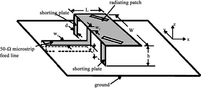
Antenna Parameters: L = Length of the patch; W = Width of the patch; Wf = Width of the 50 Ω feed line; h = Height of the radiating patch above the substrate; t = Height of the feed line above the substrate; d = Width of the shorting plates.
Figure 1. Basic geometry of MFSPA with inclined slots.
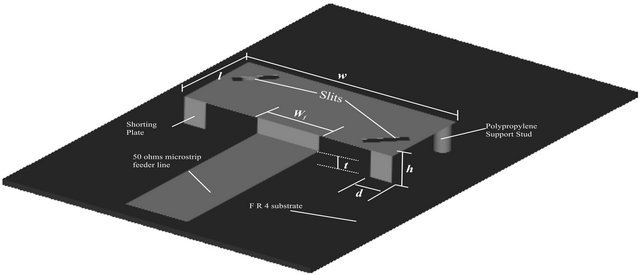
Figure 2. Auto-CAD diagram of MFSPA.
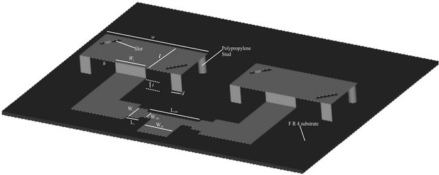
Figure 3. 2 × 1 array of slotted MFSPA.
In the 2 × 1 array of MFSPA the two adjacent patches are placed on the substrate at a distance of 7.1 cm between their centers i.e. λ/2.3, approximately equal to half wavelength. It consists of a 50 Ω microstrip line of length L50 and width W50 which is connected to a 100 Ω line of length L100 and width W100 to form a two way power divider. A matching quarter wave transformer of length Lt and width Wt is connected between 100 Ω feed line and mid point of the radiating elements in order to ensure perfect impedance matching. The array geometry and feed arrangement is shown in Figure 3. Table 1 gives the design parameters of 2 × 1 array.
3. Results and Discussions
Measurements for the return loss and the radiation patterns of the antennas are made with the Vector Network Analyzer (ROHDE & Schwarz, German made SVK Model- 7.8651). Figure 4 shows the measured return loss versus frequency plot of the single element antenna. The experimental study of single element antenna has shown that it offers an impedance bandwidth of 25.2% at a resonant frequency of 1905 MHz as shown in Figure 4 and the gain of 6.4 dBi. Figure 5 shows the radiation patterns of a single element antenna.
From Figure 6 it is clearly seen that an impedance bandwidth of 40% covering the bandwidth requirement of 1750 MHz band (1200 MHz - 1900 MHz) is obtained by 2 × 1 array configuration. The return loss curve also shows the dual band operation of the antenna. The antenna resonates at the second frequency f2 (2350 MHz) offering a bandwidth of 36% (2000 MHz - 2850 MHz). Typical measured radiation patterns for the antenna are presented in Figure 7. Good broadside patterns are obtained in the H plane. A relatively lesser cross polarization radiation in H plane is observed for the antenna array as compared to that of a single element antenna.
Table 1. Design parameters.
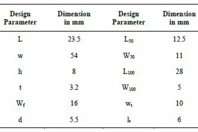
The distance “D” between the adjacent patches is D = 7.1 cm (l0/2.3); Ground plane size: 100 × 150 mm2.
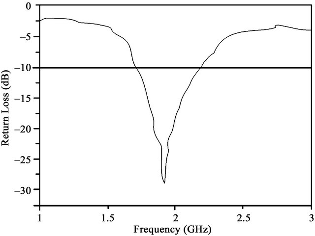
Figure 4. Return loss vs frequency plot of single element slotted MFSPA.
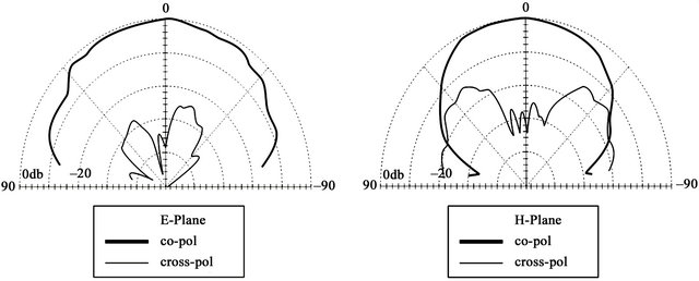
Figure 5. Radiation patterns of single element MFSPA with inclined slots.
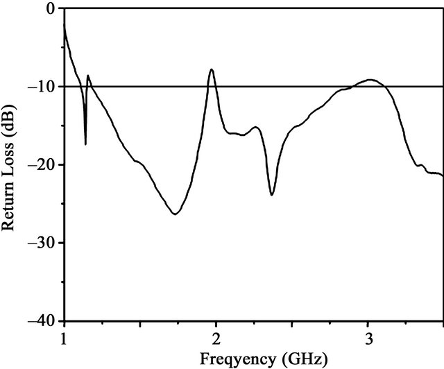
Figure 6. Return loss vs frequency plot of the 2 × 1 array of slotted MFSPA.
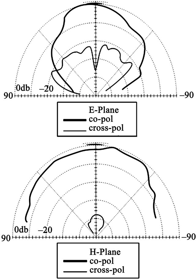
Figure 7. Radiation patterns of 2 × 1 Array of MFSPA with inclined slots.
The gain vs frequency plot for 2 × 1 array of MFSPA with inclined slots is shown in Figure 8. A considerable increase in gain i.e. 9.2 dBi against 6.4 dBi for a single element is achieved by the array configuration.
The variation of input impedance shown in Figure 9 also depicts the dual frequency operation of the array configuration.
A typical MFSPA is simulated using IE3D software and is shown in Figure 10. The return loss vs frequency curve for the same is shown in Figure 11.
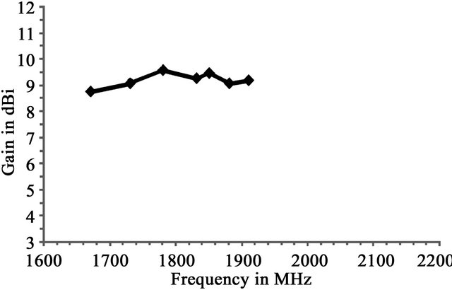
Figure 8. Gain vs Frequency plot of 2 × 1 Array.
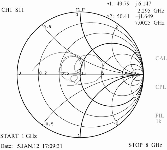
Figure 9. Variation of input impedance with frequency.
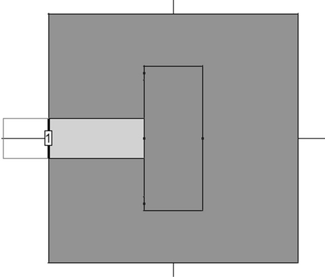
Figure 10. Simulated MFSPA.
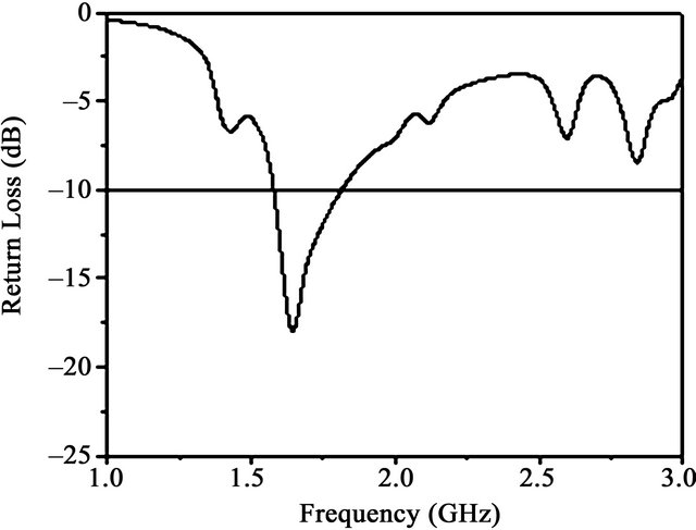
Figure 11. Return loss vs frequency plot of simulated MFSPA.
4. Conclusion
The prototype of a 2 × 1 array of MFSPA has been developed and its performance has been studied. The performance of the same is compared with that of the single element antenna. The proposed design of the 2 × 1 array provides an enhanced impedance bandwidth of 40% and 36% at the two bands with respect to the centre frequencies of 1750 MHz and 2350 MHz. The prototype of a single element antenna presents bandwidth of 25.2% at a centre frequency of 1950 MHz. Both the antennas show good broadside radiation patterns. Substantial reduction in cross polarization radiation is observed with antenna array configuration. The results show that the proposed antenna may conveniently be used for DCS base station applications and also for the other wireless applications due to its dual band operation.
REFERENCES
- K.-L. Wang, “Compact and Broadband Microstrip Antennas,” John Wiley and Sons, Inc., Chichester, 2002.
- K. Fujimoto and J. R. James, “Mobile Antenna System Handbook,” 2nd Edition, Artech House Inc., 2001.
- R. G. Vaughan and J. B. Anderson, “Antenna Diversity in Mobile Communication,” IEEE Transactions on Antennas and Propagation, Vol. 49, 1987, pp. 954-960.
- S.-Y. Lin and K.-C. Huang, “A Compact Microstrip Antenna for GPS and DCS Application,” IEEE Transactions on Antennas and Propagation, Vol. 53, No. 3, 2005, pp. 1227-1229. doi:10.1109/TAP.2004.842597
- S. W. Su and J. H. Chou, “Low Cost Flat Metal Plate Dipole Antenna for 2.4/5-GHz WLAN Operation,” Microwave and Optical Technology Letters, Vol. 50, No. 6, 2008, pp. 1686-1687. doi:10.1002/mop.23461