Advances in Chemical Engineering and Science
Vol.4 No.1(2014), Article ID:42432,11 pages DOI:10.4236/aces.2014.41009
Battery Modeling: A Versatile Tool to Design Advanced Battery Management Systems
Group Energy Materials and Devices, Department of Chemical Engineering and Chemistry, Eindhoven University of Technology, Eindhoven, The Netherlands Email: *P.H.L. Notten@tue.nl
Copyright © 2014 Peter H. L. Notten, Dmitri L. Danilov. This is an open access article distributed under the Creative Commons Attribution License, which permits unrestricted use, distribution, and reproduction in any medium, provided the original work is properly cited. In accordance of the Creative Commons Attribution License all Copyrights © 2014 are reserved for SCIRP and the owner of the intellectual property Peter H. L. Notten, Dmitri L. Danilov. All Copyright © 2014 are guarded by law and by SCIRP as a guardian.
Received November 15, 2013; revised December 15, 2013; accepted December 22, 2013
KEYWORDS
Battery Modelling; Rechargeable Batteries; Li-Ion; NiMH; Battery Management Systems (BMS)
ABSTRACT
Fundamental physical and (electro) chemical principles of rechargeable battery operation form the basis of the electronic network models developed for Nickel-based aqueous battery systems, including Nickel Metal Hydride (NiMH), and non-aqueous battery systems, such as the well-known Li-ion. Refined equivalent network circuits for both systems represent the main contribution of this paper. These electronic network models describe the behavior of batteries during normal operation and during over (dis) charging in the case of the aqueous battery systems. This makes it possible to visualize the various reaction pathways, including convention and pulse (dis) charge behavior and for example, the self-discharge performance.
1. Introduction
Sustainability is one of the main challenges of our present-day society. A sustainable economic development requires clean renewable energy sources and, therefore, efficient energy storage media. Wind, solar and tidal energy are examples of renewable but irregular energy sources that require storage to accumulate and deliver electricity reliably under these highly fluctuating conditions. Figure 1 illustrates the need for energy storage in various applications. Until recently, energy-storage and conversion devices like secondary (rechargeable) batteries, fuel cells and super-capacitors were mainly used in portable electronic appliances (notebooks, cell phones, etc.) and stand-alone equipment (reserve power supplies, power tools). Today there is a strong tendency to diversify the area of applications and hence the need for various energy-storage devices: on the one hand, bigger storage systems are applied in, for example, (hybrid) electrical vehicles and industrial-scale facilities and, on the
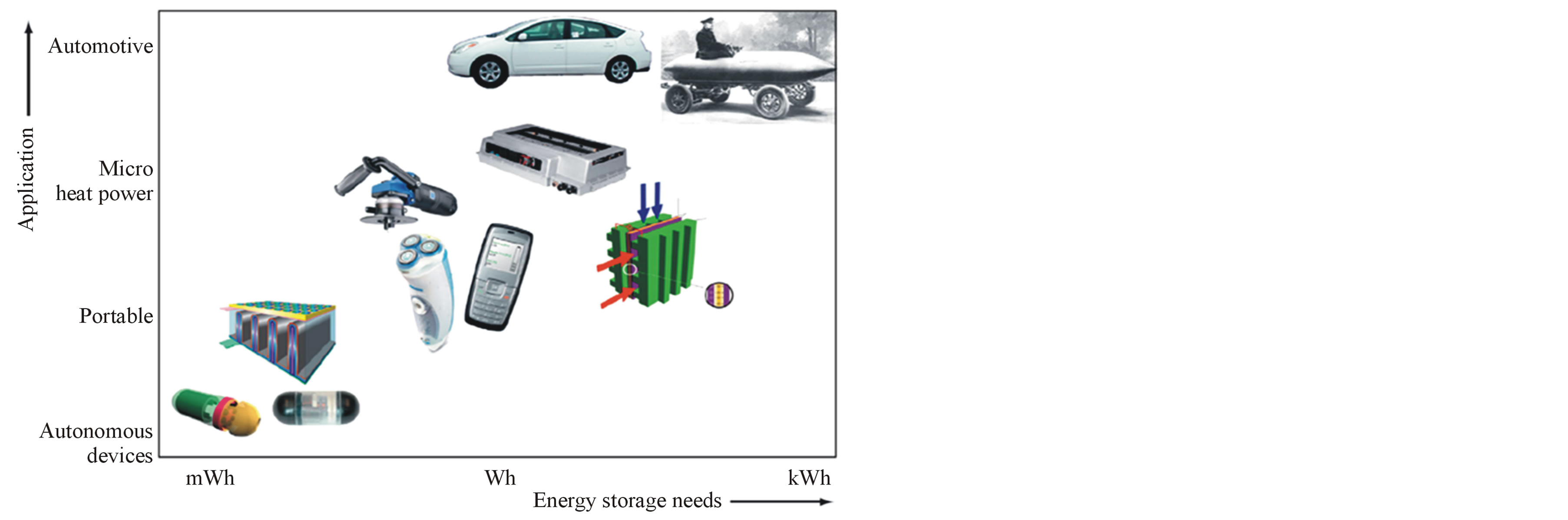
Figure 1. Future battery applications and necessary energy storage capabilities.
other hand, very small sized energy-storage devices are used, for example, wireless autonomous devices and medical implants [1,2] as is schematically represented in Figure 1.
A universal tool describing battery performance under a wide variety of conditions and applications is therefore highly desirable. Electronic network modeling delivers such universal tool and nicely visualizes the processes taking place inside rechargeable batteries. Based on these generic models, new Battery Management algorithms can be developed, which control the performance of these battery systems under all operating conditions, facilitating comfort, a long cycle life, reliability and safety. In this paper, the fundamental principles of electronic network modeling will be outlined for both Nickel Metal Hydride (NiMH) and Li-ion batteries and some modeling examples forming the core of advanced Battery Management Systems (BMS) will be presented.
2. State of the Art Rechargeable Batteries
Main types of secondary battery systems currently available on the market are presented in Table 1. Starting with the lead acid battery, new systems have been developed during the last century and the main achievement has been that the energy density has been increased continuously, enabling the new applications introduced above. Apparently, increase in energy density puts more restrictions on the safety control of these new storage systems. Although the oldest sealed lead-acid technology has a favorable cost advantage, these batteries are heavy and therefore poor in terms of specific energy. NickelCadmium (NiCd) batteries deliver significantly improved specific energy and high-(dis) charge-rate capability, but are obviously not environmentally friendly. The NiMH technology provides a high specific energy and involves no significant pollution but can build up high internal gas pressures, which might generate some problems during prolonged over (dis) charging. A relatively high self-discharge rate is another drawback of Nickel-based aqueous battery systems. The most advanced lithium-based technology offers the highest specific energy and energy density. This battery system has been developed rapidly over the last two decades in response of mobile electronic industry and more recently the automotive industry. The Cobalt-oxide based Li-ion batteries were fairly criticized because of their poor safety properties. Introduction of mixed-oxides and iron-phosphate cells has improved the safety significantly. However, Li-ion batteries require sophisticated BMS to control the safety and cycle life, making this battery system as a whole more expensive.
3. Hydrogen Storage and NiMH Batteries
An alternative way of storing energy, which has been continuously under development during the last decades, is by making use of hydrogen. Hydrogen has a record high energy content per unit of weight and is, therefore, a natural candidate as alternative energy carrier. At the same time hydrogen gas possesses a low volumetric energy density, thus advanced hydrogen storage methods is essential. It has therefore been emphasized that efficient hydrogen storage via the gas phase is also one of the key factors, enabling the future hydrogen economy, which will be based on the extensive use of hydrogendriven Fuel Cells in a wide range of stationary and portable applications. The demand for finding appropriate solutions to store hydrogen in the gas phase is, therefore, high. The basic principles of gas phase storage in Metal Hydride (MH) materials will be outlined below. Subsequently, it will be shown that these materials can be used to store large amounts of electricity in NiMH batteries.
The first step of hydrogen storage via the gas phase is dissociation of hydrogen molecules at the solid/gas interface. The as-produced adsorbed hydrogen atoms are subsequently moved towards interstitial sites inside the solid (M), inducing the absorption process. Fortunately, these reaction steps are reversible for many hydrogen storage materials and hydrogen can therefore also be desorbed. The overall reaction can be represented by
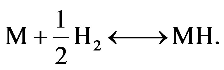 (1)
(1)
A chemical equilibrium exists between hydrogen stored in the solid and that present in the gas phase, which is generally characterized by pressure-composition isotherms, see e.g. [3]. A typical pressure-composition absorption isotherm and accompanying phase diagram are schematically shown in curve (a) and (b) of Figure 2,
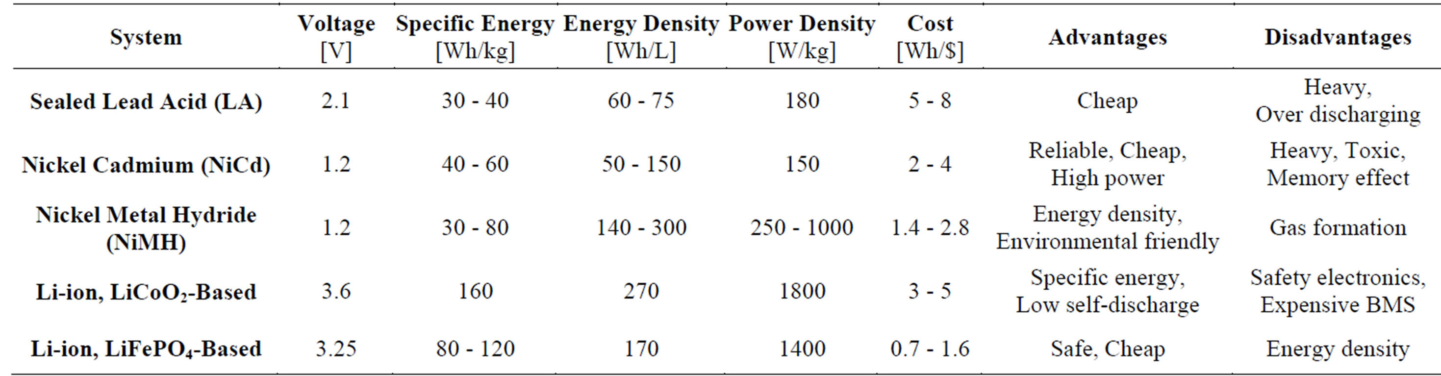
Table 1. Characteristics of various battery chemistries.
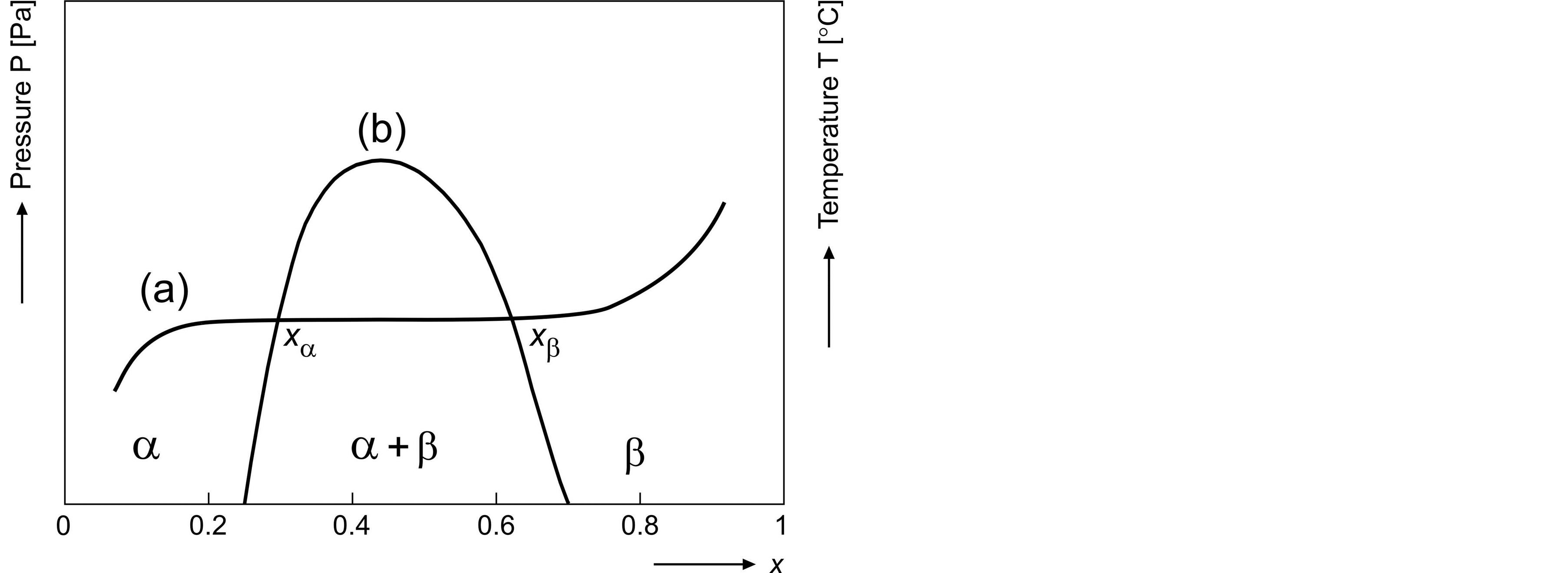
Figure 2. General representation of a pressure-composition isotherm (a) and accompanying phase diagram (b) for a typical hydrogen storage material. The solid solutions for the α and β phases are indicated together with the temperaturedependent two-phase (α + β) miscibility gap.
respectively.
During hydrogen absorption at low concentrations, a solid solution is formed, which is generally denoted as the a-phase. In this concentration region the partial hydrogen pressure  is clearly dependent on the amount of stored hydrogen. After the hydrogen concentration has reached a certain critical value (xa), phase transition occurs and the a-phase is continuously transformed into the b-phase. The pressure dependence in this two-phase coexistence region is generally characterized by a (sloping) plateau. Phase transition is completed at xb and a solid solution is subsequently formed by the bphase only. This typical three-step process will play an important role in the present paper with respect to electrochemical energy storage in the case of rechargeable NiMH batteries.
Hydrogen storage can also be induced electrochemically in strong alkaline electrolyte, according to
 (2)
(2)
The operation principle of NiMH batteries is based on the latter reversible electrochemical process and hydrogen storage is induced by a current-driven charge transfer reactions. A layout of a NiMH battery, containing a hydride-forming MH electrode and a Ni electrode is shown in Figure 3. A porous polymer separator electrically insulates the electrodes. Both separator and electrodes are impregnated with a strong alkaline solution (usually of the order of 7 mol·l−1 KOH) that provides the ionic conductivity between the two electrodes. The overall electrochemical reactions, occurring at both electrodes during charging (ch) and discharging (d) can, in their most simplified form, be represented by
 (3)
(3)

Figure 3. Concept of a sealed rechargeable NiMH battery.
and
 (4)
(4)
During charging divalent NiII is oxidized into the trivalent NiIII state and a proton and electron are released from the Ni electrode. The proton reacts with  in the electrolyte to give water. The electrons are transported via the charger to the other, metal (M), electrode where water is reduced to atomic hydrogen atoms which are, subsequently, absorbed by the hydride-forming compound to give MH. The reverse reactions take place during discharging. The net effect of this reaction sequence is that hydrogen is transported from one electrode to the other.
In general, exponential dependences between the partial anodic/cathodic currents and the applied electrode potential are observed under kinetically controlled conditions, as is schematically depicted in Figure 4 (dashed curves). The potential scale is given with respect to an Hg/HgO reference electrode. The equilibrium potential of the Ni electrode under standard conditions is more positive ( mV) than that of the MH electrode. The equilibrium potential of the MH electrode
  depends on the partial hydrogen pressure of the hydrideforming materials, according to
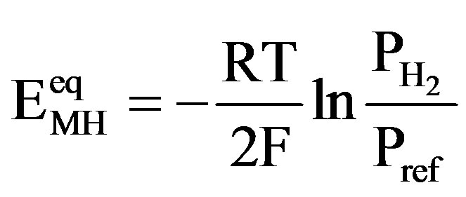 , (5)
, (5)
where  is the Faraday constant,
  the gas constant,
  the temperature [K],
  the equilibrium hydrogen pressure [Pa] and
  is the reference pressure of 1 bar @ 105 Pa. Because the preferred partial hydrogen pressure of MH electrode materials is of the order of up to a few 0.01 bars,
  ranges generally between –930 and –860 mV. This implies that the theoretical open-circuit potential of a NiMH battery is approximately 1.3 V
 . During galvanostatic charging with
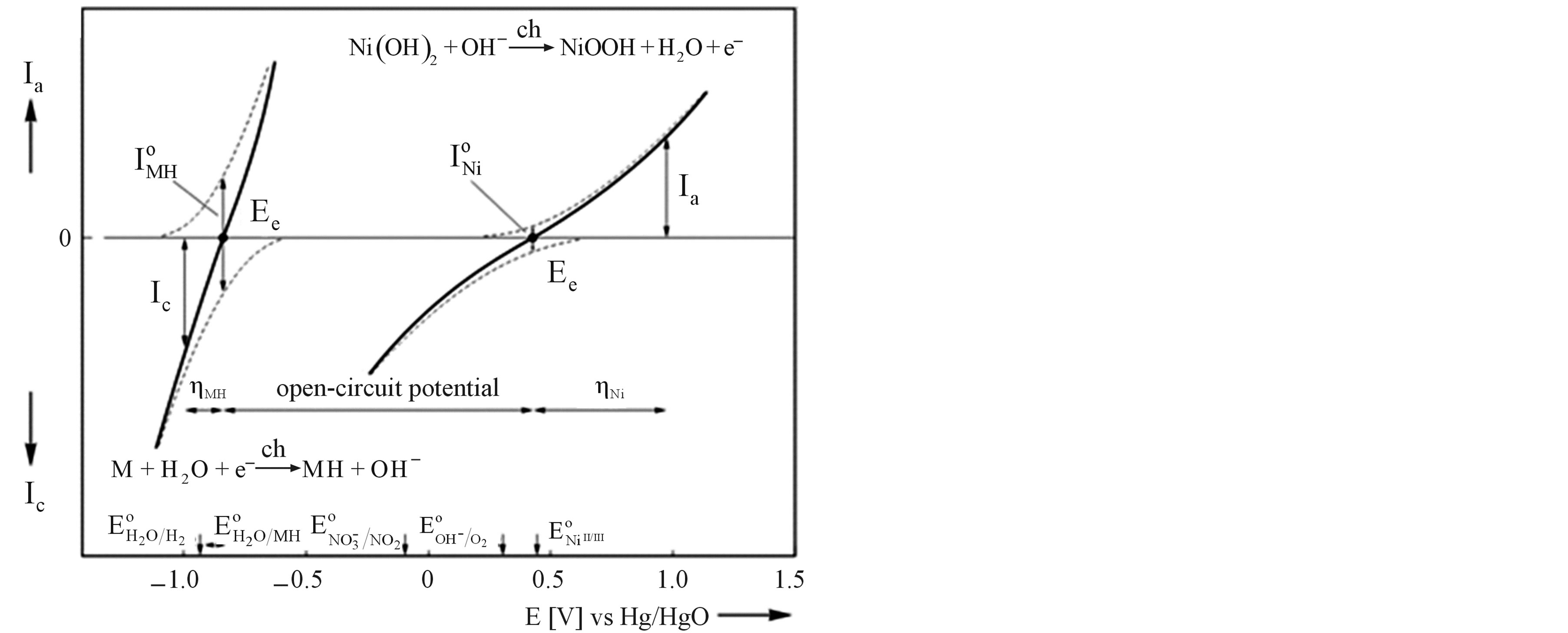
Figure 4. Schematic representation of the current-potential curves for a Ni and MH electrode (solid lines), assuming kinetically controlled charge transfer reactions. The partial anodic and cathodic reactions are indicated as dashed lines. The exchange currents ( ) are defined at the equilibrium potentials (
 ). Potentials are given with respect to an Hg/ HgO reference electrode. Besides the redox potentials (
 ) of the main electrode reactions those of some side reactions are also indicated.
a constant current an overpotential  will be established at both electrodes. The magnitude of each overpotential component (
 and
and  in Figure 4) is determined by the kinetics of the charge transfer reactions. An electrochemical measure for the kinetics of a charge transfer reaction is generally considered to be the exchange current
 , which is defined at the equilibrium potential
  at which the partial anodic current equals the partial cathodic current (see Figure 4). In case of the Ni electrode,
  is reported to be relatively low, which implies that at a given constant anodic current
  the established overpotential at the Ni electrode is relatively high (Figure 4). In contrast, the kinetics of the MH electrode is reported to be strongly dependent on the materials composition. Assuming a highly electro-catalytic hydride-forming compound, this implies that the current-potential curves for the MH electrode are very steep in comparison to those for the Ni electrode, resulting in a much smaller value for
  at the same cathodic current
 , as is schematically shown in Figure 4. It is evident that the battery voltage under current flow is a summation of the open-circuit potential and the various overpotential contributions, including the ohmic potential drop
  caused by the electrical resistance of the electrolyte (Re). The reverse processes occur during discharging, resulting in cell voltage lower than 1.3 V.
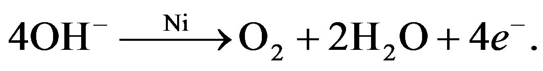
To ensure proper functioning of sealed rechargeable NiMH batteries under a wide variety of operating conditions, the Ni electrode is designed to be the capacitydetermining electrode, as is schematically depicted in Figure 3. Such a configuration forces side reactions to occur at the Ni electrode both during overcharging and overdischarging. During overcharging  ions are oxidized at potentials more positive with respect to the standard redox potential of the
  redox couple (about 0.3 V with respect to Hg/HgO reference in Figure 4) and oxygen evolution is induced at the Ni electrode, according to
 (6)
(6)
As a result, the partial oxygen pressure inside the sealed cell starts to rise. Advantageously, oxygen can be transported to the MH electrode, where it can be reduced at the MH/electrolyte interface at the expense of the hydride-formation reaction (4), according to
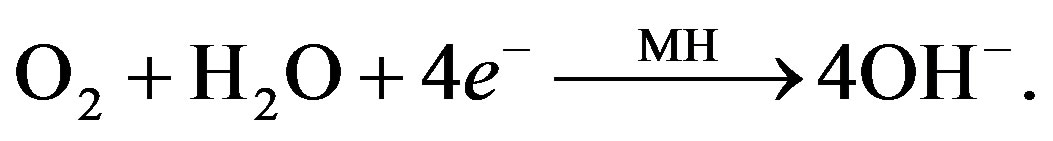 (7)
(7)
Both the oxygen evolution and the so-called oxygen recombination reaction are schematically represented in Figure 3 by the curved arrows. Because the overpotential for the recombination reaction at the MH electrode is relatively high it has been argued that its rate is most probably transport-controlled by the oxygen supply through the electrolyte [4]. The oxygen recombination mechanism ensures that the partial oxygen pressure inside the NiMH battery will be kept low. It should be noted that both oxygen and hydrogen gas are present during overcharging as has recently been analyzed and simulated [5,6]. Explanation of the layout and the basic principles of a NiMH battery can be found in [7,8].
4. Li-Ion Batteries
Figure 5 illustrates the general concept of a lithium-ion battery. The Li-ion battery consists of two electrodes, a porous separator impregnated with a non-aqueous elec-
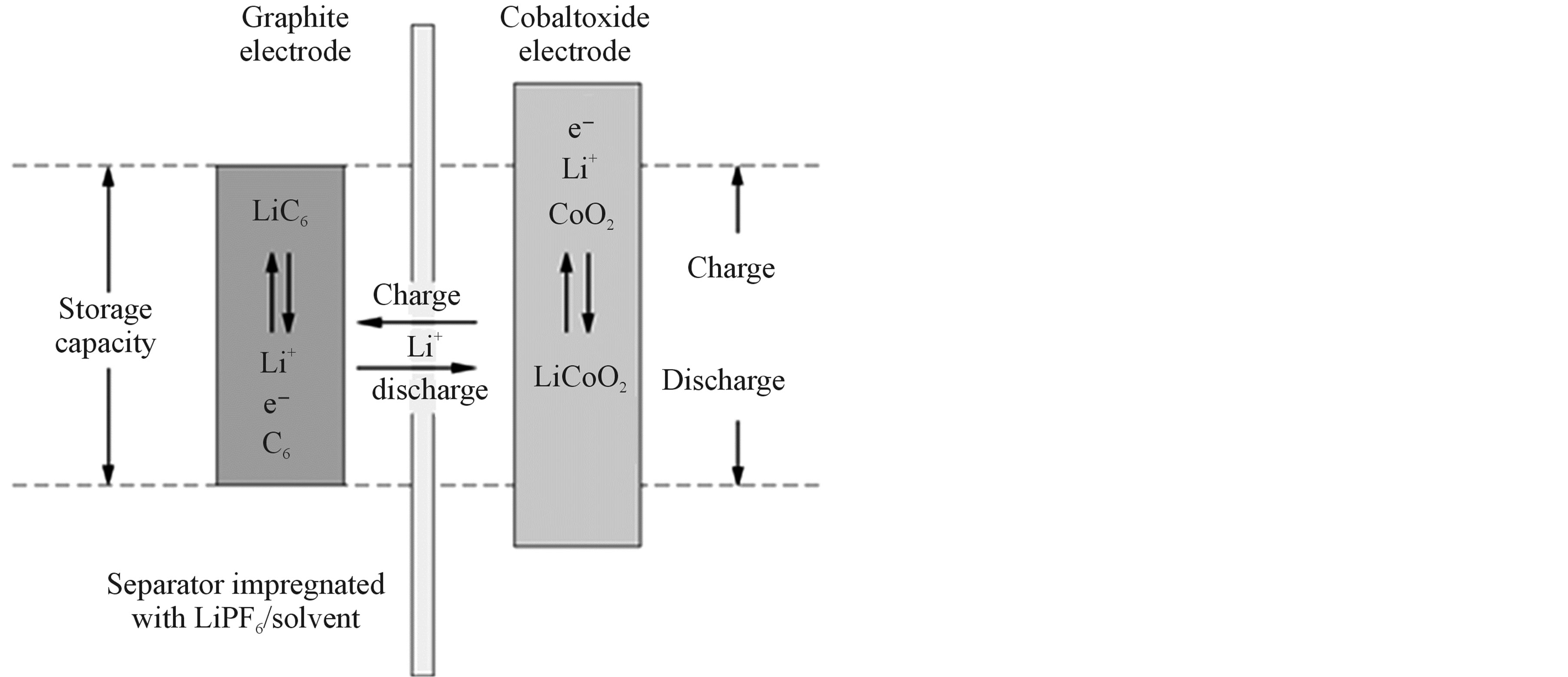
Figure 5. Concept of a sealed rechargeable Li-ion battery based on the lithium cobalt-oxide/graphite chemistry.
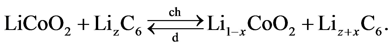
trolyte, and two current collectors (not shown). Lithium cobalt oxide (LiCoO2) typically serves as active electrode material for the positive electrode. The negative electrode is usually made of lithiated carbon or graphite (LiC6). Electrodes are electrically isolated by means of a porous polymer separator impregnated with an organic electrolyte containing lithium salt. Copper foil is used as current collector for the negative electrode and aluminum as collector for the positive electrode.
The corresponding electrochemical reactions, leading to reversible energy storage are also schematically shown in Figure 5. The main electrochemical storage reaction at the lithium cobalt oxide electrode can be represented by
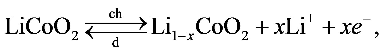 (8)
(8)
where , describing the extraction of
  ions from the positive electrode during charging and the insertion of
  ions during discharging, where
  represents the mol-fraction of lithium inside the positive electrode. Note that for a proper reversible functioning of a lithium-ion battery not all lithium can be removed from the positive electrode. This implies that
  can, in practice, not become higher than 0.5 in
 .
.
The corresponding reaction at the negative electrode can be described by
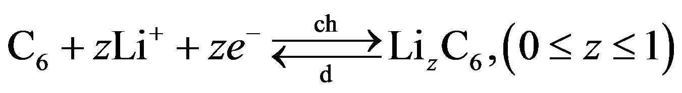 (9)
(9)
where z gives the mol-fraction of  ions inside the negative electrode. As a result of these electrochemical charge-transfer reactions,
  ions must cross the electrolyte under current-flowing conditions (see Figure 5). The electrolyte in lithium-ion batteries is based on a dissociated lithium-containing salt, for example, lithium hexafluorophosphate (LiPF6) or lithium perchlorate (LiClO4), which is an ionic-conductive medium. Various mixtures of ethylene carbonate (EC), diethyl carbonate (DEC), and dimethylcarbonate (DMC) are used as nonaqueous solvents. The ions in the electrolyte are transported by both diffusion and migration, the latter process being induced by the electric field between the electrodes across the electrolyte. The overall main electrochemical storage reaction can then be represented as
 (10)
(10)
Interestingly, it can be concluded that the fundamental energy storage mechanism in both NiMH and Li-ion batteries is exactly the same, by making use of host materials in which either hydrogen or lithium are stored in a safe way.
5. Modeling NiMH Batteries
Equivalent electronic network models have been developed for various types of rechargeable batteries [4,7-10]. These models are all based on the macroscopic description of the fundamental (electro) chemical and physical processes occurring inside these battery systems, enabling quantification of these processes. Reported simulation results are in good agreement with experiments [4,7-10]. Figure 6 represents the electronic network model for a NiMH battery, in which the two electrodes and, in between, the electrolyte can be recognized (see Figure 3). Three parallel reaction pathways can be distinguished at the nickel electrode: the main electrochemical storage reaction (3); the oxygen evolution overcharge reaction (6) and the hydrogen evolution overdischarge reaction. Similarly, three reaction pathways can be discerned at the MH electrode, including the main electrochemical hydride formation reaction (4); the oxygen recombination reaction induced during overcharging (7) and the hydrogen recombination reaction induced during overdischarging. Furthermore, two domains can be distinguished in Figure 6, the electrical and the chemical domain, separated by an ideal transformer. Energy storage in the electrical domain is modeled by electrical double-layer capacitances Cdl, which is physically caused by electrical charging of solid electrodes in contact with ionic electrolytes. The coupling between the electrical and chemical domains is represented by ideal transformers [8]. Each electrochemical-to-chemical transition pathway j is modeled by an ideal transformer in series with two antiparallel diodes Dj, with one diode representing the kinetics of the oxidation (Ox) reaction and the other that of the reversed, reduction (Red), reaction.
In the chemical domain,  represents the thermodynamically determined standard redox potential of the Ni(OH)2/NiOOH redox system. The chemical capacitances
  and
and  represent the concentra-
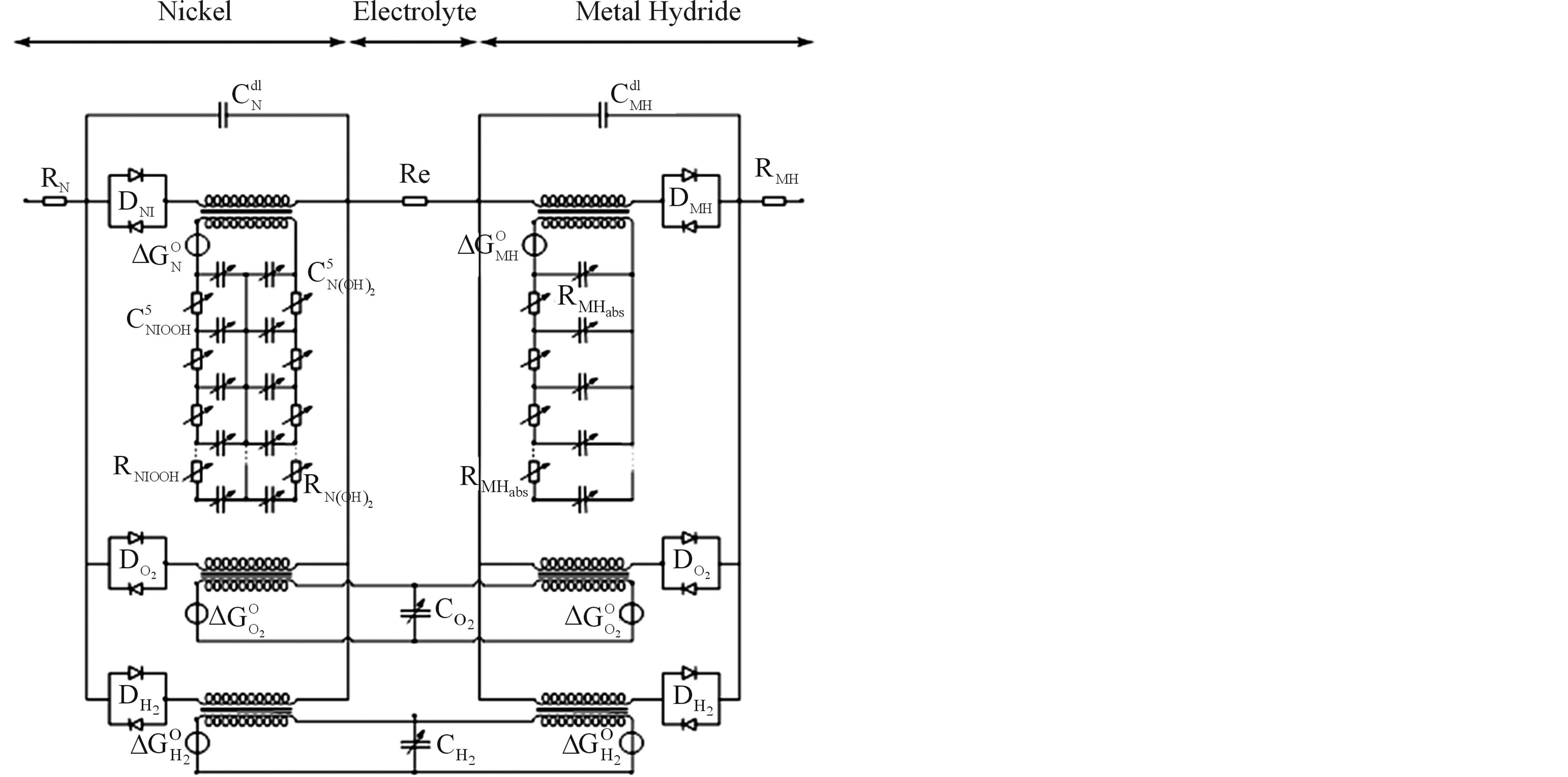
Figure 6. Electronic network model for a NiMH battery.
tion of the oxidized and reduced Nickel species. The diffusion process of protons inside the Nickel electrode is modeled by an RC-ladder network. The electrode has therefore been divided into spatial elements. The capacitances on the left-hand side consider the molar amounts of the NiOOH species in each spatial element i and the capacitances on the right-hand side represent the molar amounts of the Ni(OH)2. The top of the RC-ladder network at x = 0 gives the surface concentrations at the electrode/electrolyte interface, at which the electrochemical charge transfer reaction takes place. The bottom of the ladder network represents the electrode/current collector interface at x = l. The diffusing H+ ions (protons) can only cross the electrode/electrolyte interface as a result of the electrochemical charge transfer reaction, whereas they cannot cross the electrode/current collector. Resistances  and
and  represent the diffusion coefficient of H+ ions inside the nickel electrode (DH+). A concentration profile of Ni(OH)2 and NiOOH species developed during the (dis) charging process inside the electrode induces changes in chemical potentials of both species.
Apart from the main electrochemical storage reaction, the oxygen evolution reaction will take place during overcharging in aqueous battery systems. Similar as in the case of the Ni reaction this charge transfer reaction can be modeled by two anti-diodes ( ) in series with a transformer, again representing the transfer from the electrical to the chemical domain. Similarly, the hydrogen evolution reaction, taking place during overdischarging, can be represented by two diodes (
 ).
).
As the present network modeling approach is generic, the same structure and terminology can be adopted for the MH electrode, including the various charge transfer reactions at the MH electrode and hydrogen diffusion inside the MH electrode. Again three reaction pathways can be distinguished. From Figure 6 it is clear that oxygen is evolved at the Ni electrode during overcharging, which can recombine at the MH electrode. From conventional reaction kinetics it is obvious that an oxygen pressure will be build-up inside the NiMH battery during overcharging. This pressure can be modeled by a capacitance  and represents the total molar amount of oxygen present inside the battery (Figure 6). Similarly, the hydrogen pressure is modeled by
 .
.
Based on the electronic network model presented in Figure 6, the operation of a NiMH battery has been simulated under constant current charging conditions. After giving each parameter a physically realistic starting value and defining an appropriate cost function, an optimization algorithm has led to the result shown in Figure 7. It is clear that initially the NiMH battery voltage increases slowly as a function of time, i.e. as a function of State-of-Charge, to increase more steeply when the battery is approaching the fully charged state. The internal gas pressure is initially very low but starts to compete with the main electrochemical storage reaction at about 25% SoC. The pressure can become as high as 5 bar in this simulation which agrees well with our experiments. Resulting from the high partial oxygen pressure inside the gas phase the recombination reaction at the MH electrode is started. It has been analyzed that especially this recombination reaction is responsible the heating up of Ni-based battery batteries as can be seen on the temperature curve which increases steeply close to 100% SoC up to 60˚C in this example. In turn, this temperature increase reduces the overpotentials of all electrochemical charge transfer reactions, resulting in a decrease of the battery voltage at the end of the charging process. Advantageously, this voltage decrease is often used as simple cutoff criteria to terminate the charging process of Ni-based battery systems.
One interesting example of our network model is to visualize the self-discharge behavior of Ni-based battery systems. Figure 8 shows the self-discharge behavior as a function of time at various ambient temperatures after the
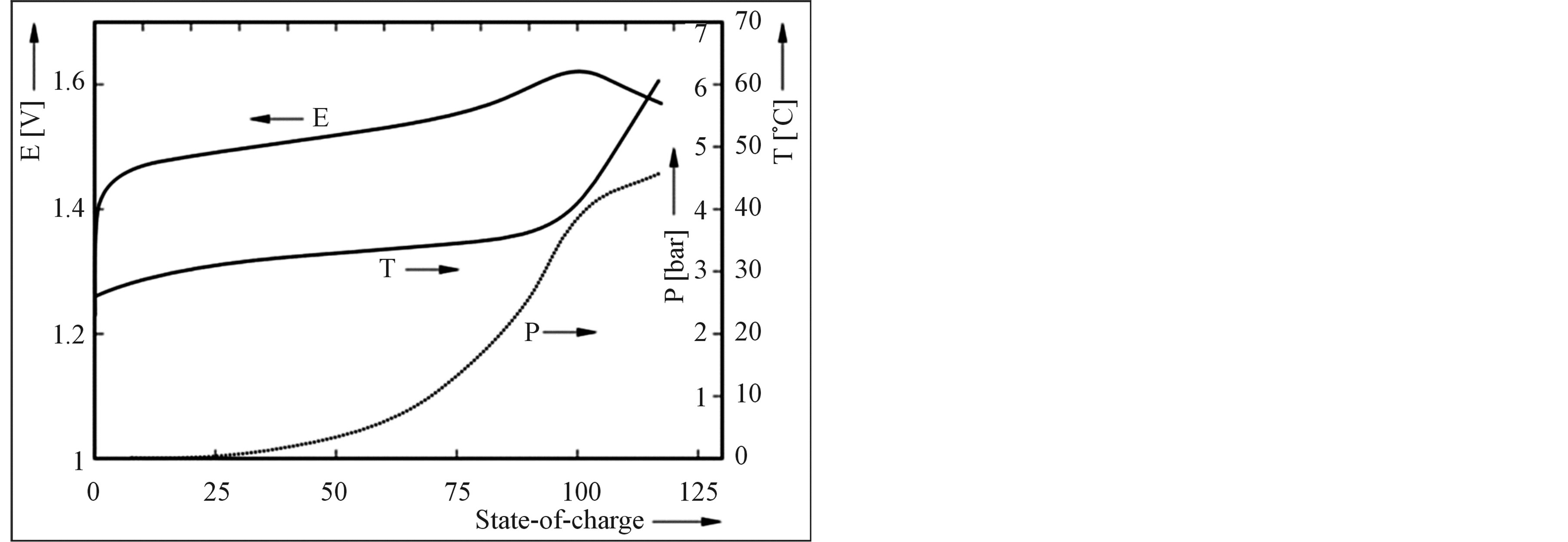
Figure 7. Simulated V, P, T-curves of NiMH upon constant current charging.
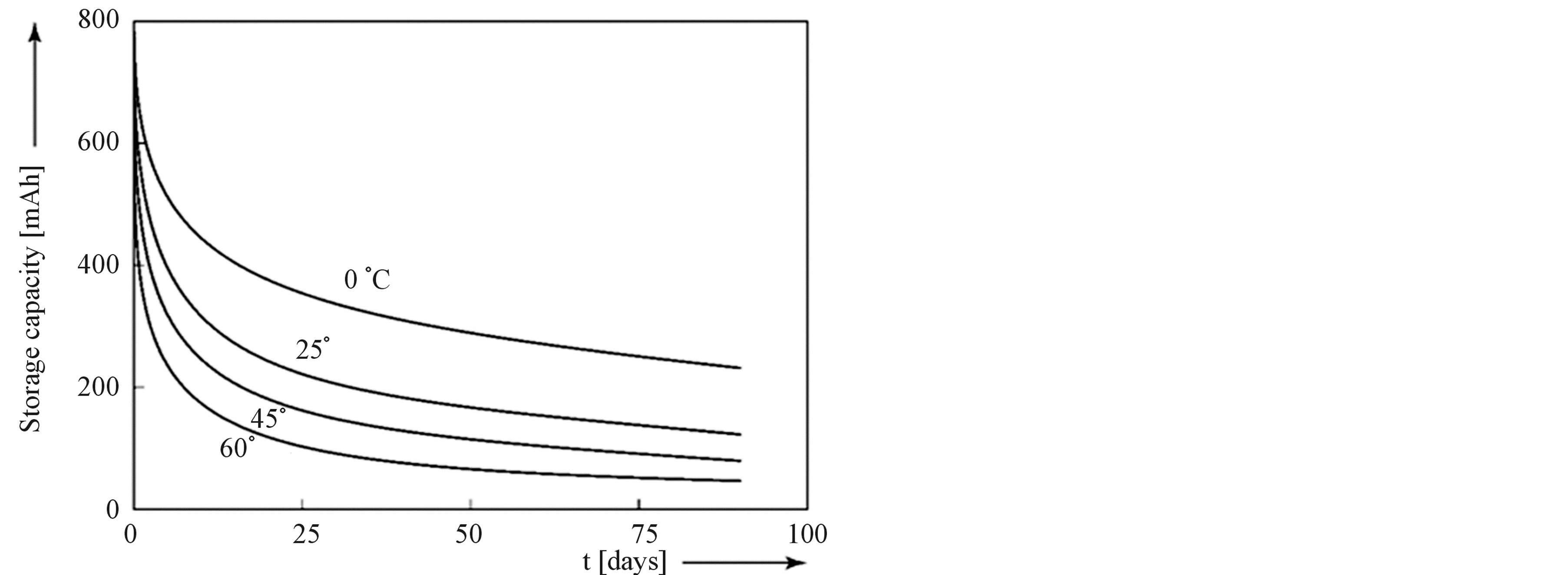
Figure 8. Calculated self-discharge behavior of Ni-based aqueous battery systems at various ambient temperatures.
battery was fully charged in the simulations up to 100% SoC. Clearly the self-discharge follows an exponential decay and is more pronounced at higher temperatures, which can be well explained by conventional reaction kinetics. Interestingly, by considering the electronic network model the phenomenon of self-discharge can be nicely explained: after switching off the charging current in the external circuit most of the electricity has been converted into chemical energy by letting the current flow through the oxidation diode into the transformer towards the chemical domain. However, from Figure 6 it is also clear that current can flow back from the chemical domain, via the backward diode towards the oxygen side reaction part, forming oxygen gas at the expense of the stored charge in the Nickel electrode. The origin of the self-discharge process must therefore be sought in the thermodynamics of the Ni electrode making it thermodynamically unstable in aqueous solutions. Fortunately the kinetics of the oxygen reaction is relatively poor so that these systems still are very attractive as electricity storage devices in many applications such as in, for example, hybrid electrical vehicles.
6. Modeling Li-Ion Batteries
The electronic network model for Li-ion batteries is shown in Figure 9 and is essentially very similar to that of NiMH. The LiCoO2 electrode model is shown on the left-hand side in Figure 9 and the LiC6 electrode model on the right-hand side. The electrolyte is shown in between the two electrodes and facilitates ionic conductivity. Two double layer capacitances (Cdl) representing the two electrodes can be recognized in the chemical domain together with the diodes (Di) representing the charge transfer reactions and the ohmic resistances (Ri) inside both electrodes. As hardly any side-reactions occur when (dis) charging is controlled in a proper way, only a single charge transfer reaction has to be included in the electronic network model. After the charge transfer reaction has taken place, electricity is converted into the chemical species in the chemical domain, which is again schematically indicated by transformers. The diffusion processes inside both electrodes are also modeled by ladder networks, including capacitors and resistances and representing the concentration and the diffusion of Li-ions within both intercalation electrodes, respectively.
As far as the electrical and chemical domains of both electrodes are concerned the similarity with Ni-based systems is very close. In the case of aqueous battery systems, the electrolyte can be modeled by a simple resistance Re (see Figure 6) as the ionic concentration in the electrolyte is very high, i.e. more than 8 molar KOH [8,10]. In the case of organic Li-ion batteries the ionic concentration is, however, much lower, of the order of 1.5 molar and, consequently, the mathematical descripttion of the transportation process becomes much more complicated [11,12]. Due to these low concentrations
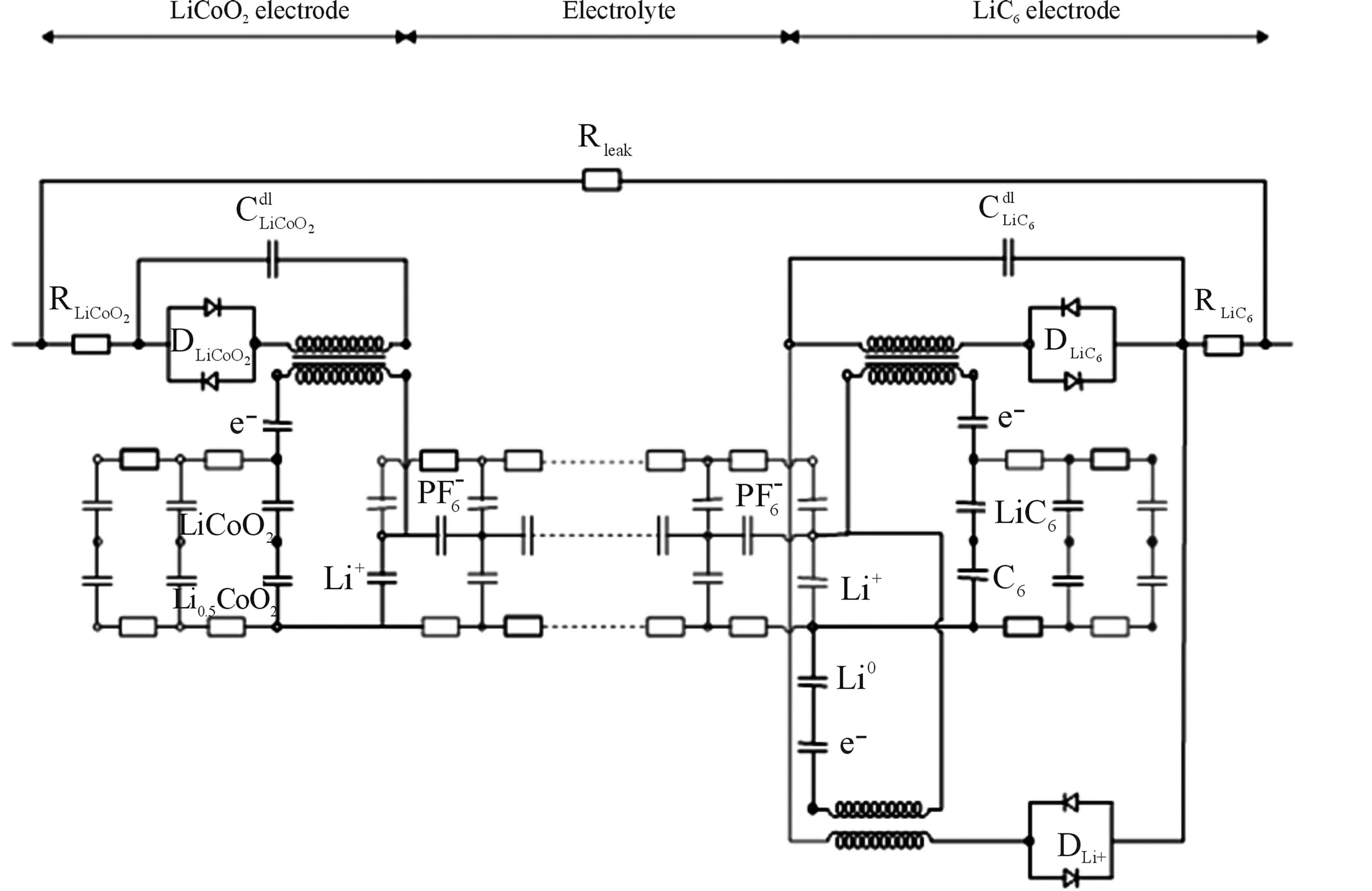
Figure 9. Electronic network model of Li-ion battery.
both diffusion and migration has to be included. These complex processes have been mathematically derived in [8,12] and can be represented by a complex ladder network in Figure 9 in which both the  and
and  ions, in the present example, play an important role. The selfdischarge of Li-ion takes place at a much lower magnitude and the mechanism is therefore quite deviating from that of Ni-based battery systems. Assuming that the selfdischarge within Li-ion batteries is due to the electronic conductivity of the electrodes and electrolyte this can be modeled by a temperature-dependent resistor Rleak across the electrodes. The temperature-dependence has been described by an Arrhenius type of representation [8,13].
Application of mathematical modeling of Li-ion batteries is successful in the prediction of the voltage and current evolution during (dis) charging, as an example shows in Figure 10. Here a constant-current-constantvoltage (CCCV) charging regime is applied to a Li-ion battery, followed by a 30 minutes resting period and the cycle is completed by constant current discharging until the cut-off voltage of 3.0 V is reached. Good agreement between the model (red line) and experimental result (blue dots) is obtained. One of the advantages of electronic network modelling is that the battery operation becomes completely transparent implying, for example, that the thermodynamically-determined open-circuit voltage of the battery can be visualized as a function of SoC, i.e. EMF dependence on SoC, together with the individual kinetic overpotential contributions. The EMF curve is represented by the green curve in Figure 10. On top of this curve the individual overpotential contributions are added. The difference between the EMF curve and the pink curve shows the charge transfer kinetics, the subsequent cyan curve represents the Li-diffusion contributions inside the electrodes and the yellow curve corresponds to the overpotential across the electrolyte. Finally, after adding ohmic losses, the total battery voltage is represented by the red line. From this simulation it be-
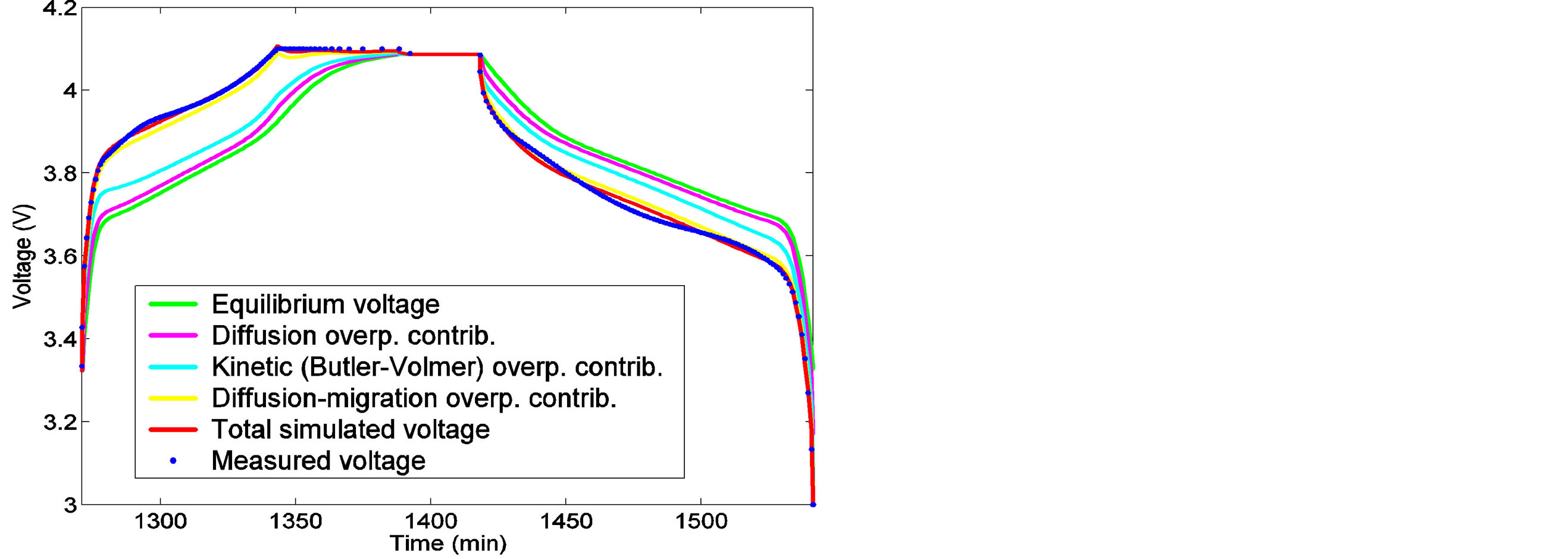
Figure 10. Voltage modeling of Li-ion battery and various contributions.
comes clear that the overpotential losses across the electrolyte seems to be most dominant (see voltage difference between the cyan and yellow curves). A more detailed analysis of the concentration profiles of Li+ ions inside the electrolyte during the CCCV charging process can be found in Figure 11, (see complete derivations in [12]). Starting with the equilibrium situation a steep concentration gradient is initially built up when the current is switched on at t = 0, to quickly reach the steady-state situation in the CC-mode. Steady-state is characterized by a linear concentration gradient. It is worthwhile to note that the Li+ concentration becomes very low at the LiC6 electrode/electrolyte interface. When the charging process is changed from the CC-mode into the CV-mode the current obviously decreases. Consequently, the concentration profile level off to the equilibrium state when the current reaches very low levels at the end of the charging process.
7. BMS and Modeling
Proper functioning of rechargeable batteries is of primary importance for any electrical appliance but especially for electrical vehicles. Modern BMS provides the user a number of important diagnostics, such as the remaining operation time, remaining charge and power capability. Therefore, BMS is a key element of any battery-powered device. The mathematical battery models developed can form the core of such BMS. However, it has become clear that the performance of batteries may deteriorate during its cycle life, in particular the capacity fades and impedance grows, leading to a reduced storage capacity and battery power.
A Solid Electrolyte Interface (SEI) is known to be present at the surface of the negative electrode of Li-ion batteries. It is ionic conductive, but electronic resistive. Still, electrons can cross the SEI layer due to electron
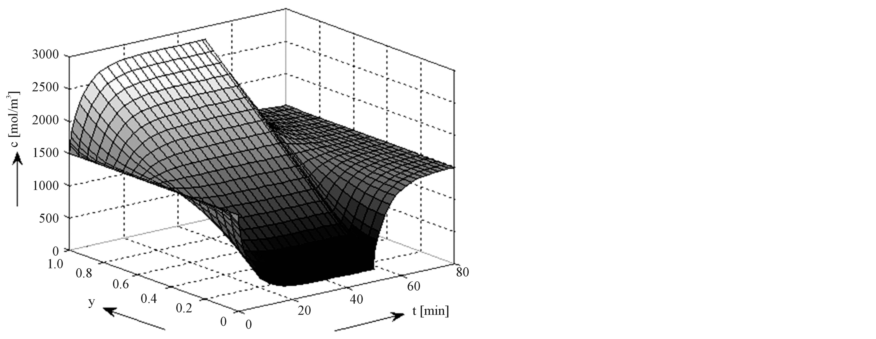
Figure 11. Development of Li+ ions concentration profile in the electrolyte during CCCV charging.
tunneling and reduce the solvent, producing insoluble lithium salts. The SEI protects the negative electrode from aggressive solvents, however, it captures some amount of electrochemically active lithium, thus reducing the battery storage capacity and increasing the impedance. The SEI formation is generally accepted as one of the main processes responsible for battery degradation. Simultaneously, a decomposition process may also develop at the surface of the positive electrode when the Lithium content becomes lower than 0.5 in Equation (8). As a result, part of the active electrode material becomes inactive. These two competing processes result in experimental capacity degradation curves of complex shape (see Figure 12, [9]). Two intervals can be discerned where the capacity fade occurs at different rates. The left-hand side of the plots corresponds to the case when SEI formation dominates the overall capacity loss. At some cycle numbers the capacity loss of positive electrode becomes more dominant limiting the overall battery storage capacity. A more theoretical explanation of these degradation processes can be found in [14-17]. The model is successful in describing the complex shape of capacity degradation curves. Particularly, Figure 12 reveals that the model simulates the capacity degradation of a cylindrical Li-ion batteries under a wide variety of operating conditions, including charging C-rate, maximum cut-off voltage and temperature. All these parameters have a clear influence on the cycling stability. The agreement between the simulation (red lines) and experiment (blue dots) is excellent in all cases. Figure 12 illustrates that ageing is accelerated at higher C-rates, higher cut-off voltages and remarkably lower temperatures.
Based on the knowledge of the ageing processes and taking into account these negatively induced side effects, sophisticated BMS have been proposed [18]. These algorithms include very accurate adaptive State-of-Charge (SoC) determination and Boostcharging. These results are especially interesting for application in Plug-in Electrical Vehicles, since these vehicles, without a doubt, will use Li-based batteries. It is known that Li-ion batteries usually are charged according to CCCV charging regime. Boostcharging [19] is characterized by a short boostcharge period (tboost), during which a high current (Imax) or a maximum voltage (Vmax) is attained, followed by a conventional CCCV period (Figure 13). Charging can be very fast (Figure 14). Fully discharged batteries, at 0% Depth-of-Charge (DoC), can be quickly recharged within 5 and 10 minutes to approximately 35% and 60% of its nominal capacity, respectively. Figure 15 shows that 5 min. boostcharging with additional standard CCCV charging does not have any negative effect on the cyclelife compared to standard CCCV charging, implying that degradation is initiated at high levels of States-of-
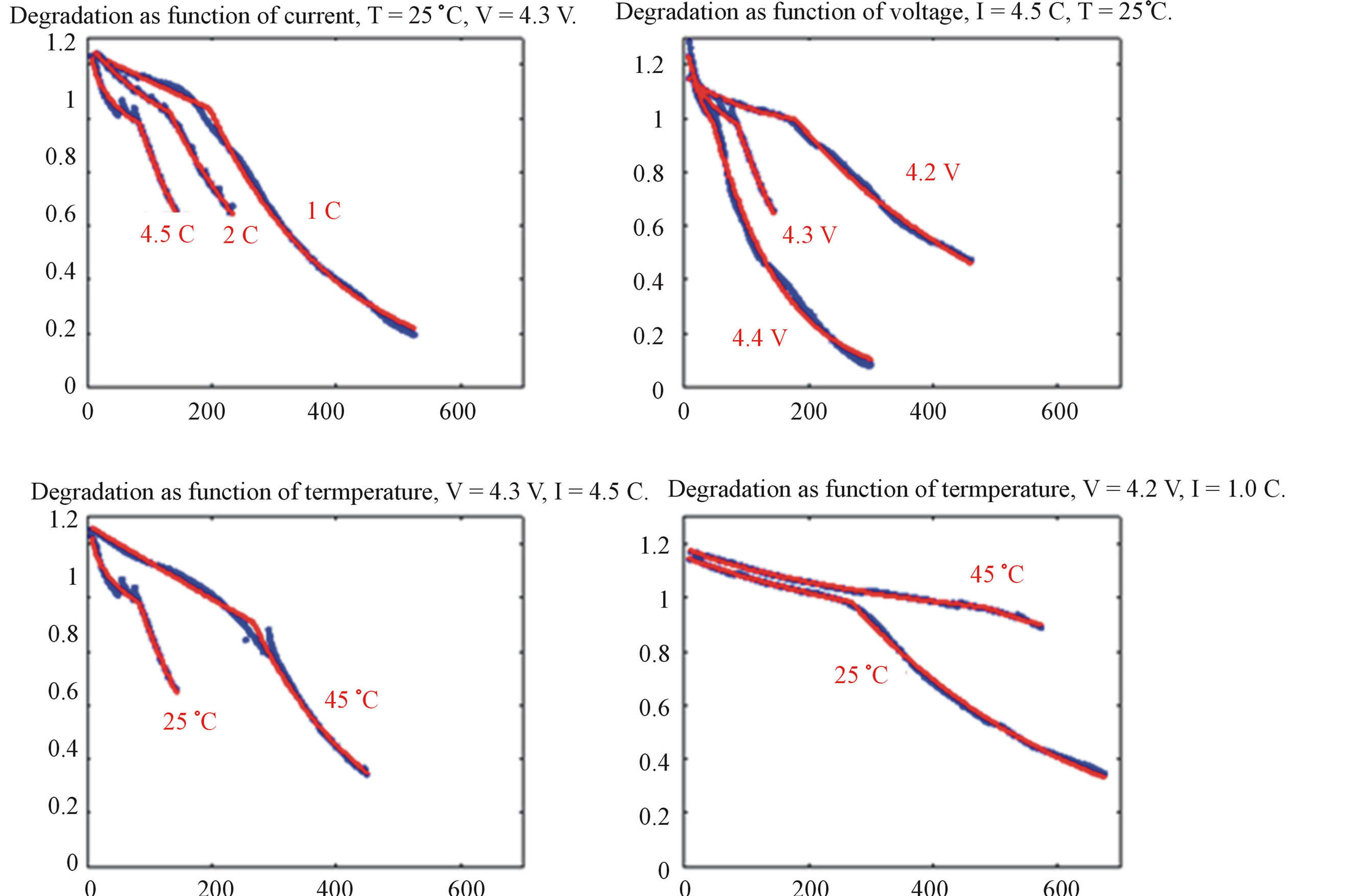
Figure 12. Influence of operation regime on capacity degradation. Experimental capacity degradation represented by blue dots, modeled by the red lines.
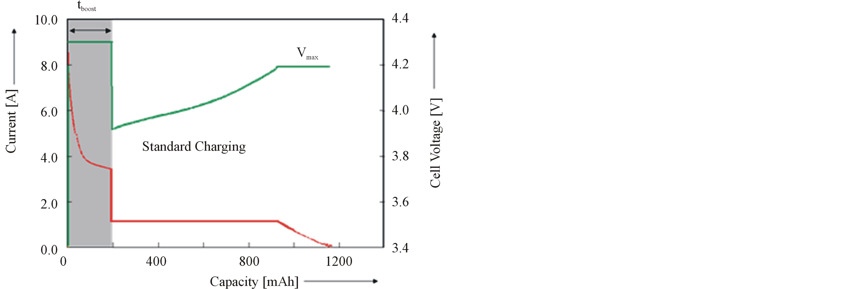
Figure 13. Basic principles of boostcharging.
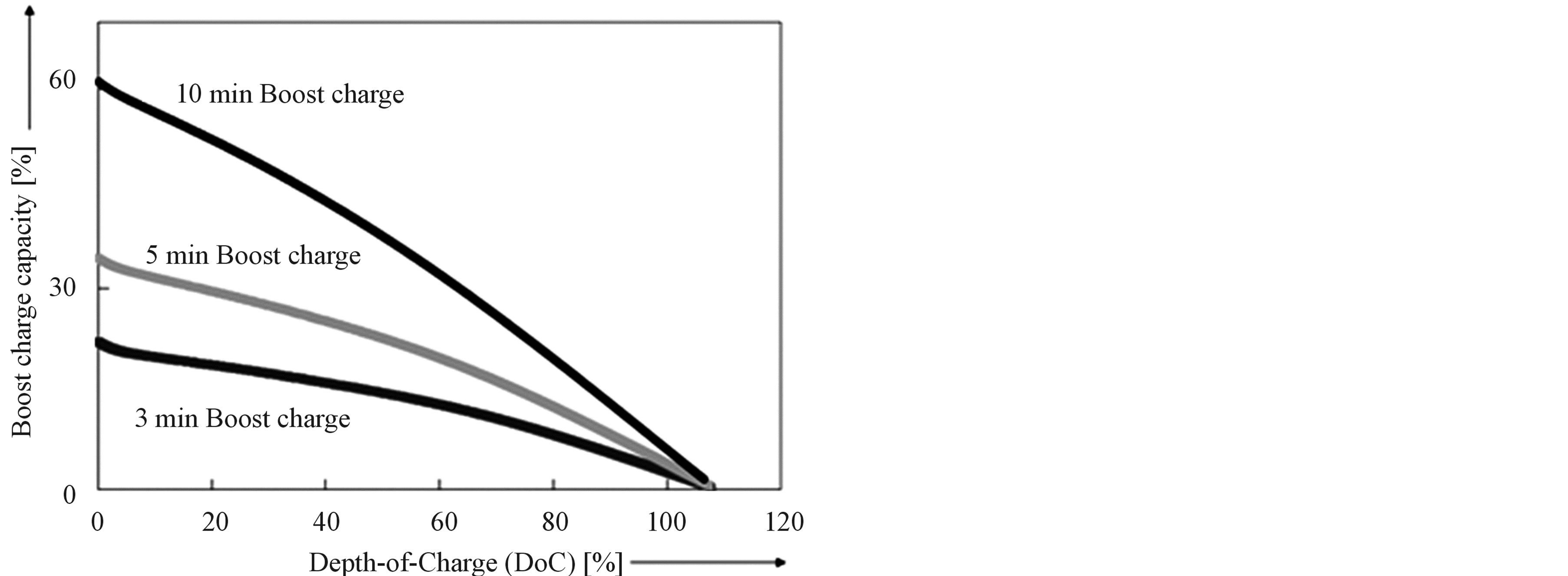
Figure 14. Impact of boostcharging as a function of initial Depth-of-Charge (DoC) for cylindrical Li-ion (Sony) batteries. The different lines give the amount of charge, which can be gained after 3, 5 and 10 min of boostcharging at 4.3 V.
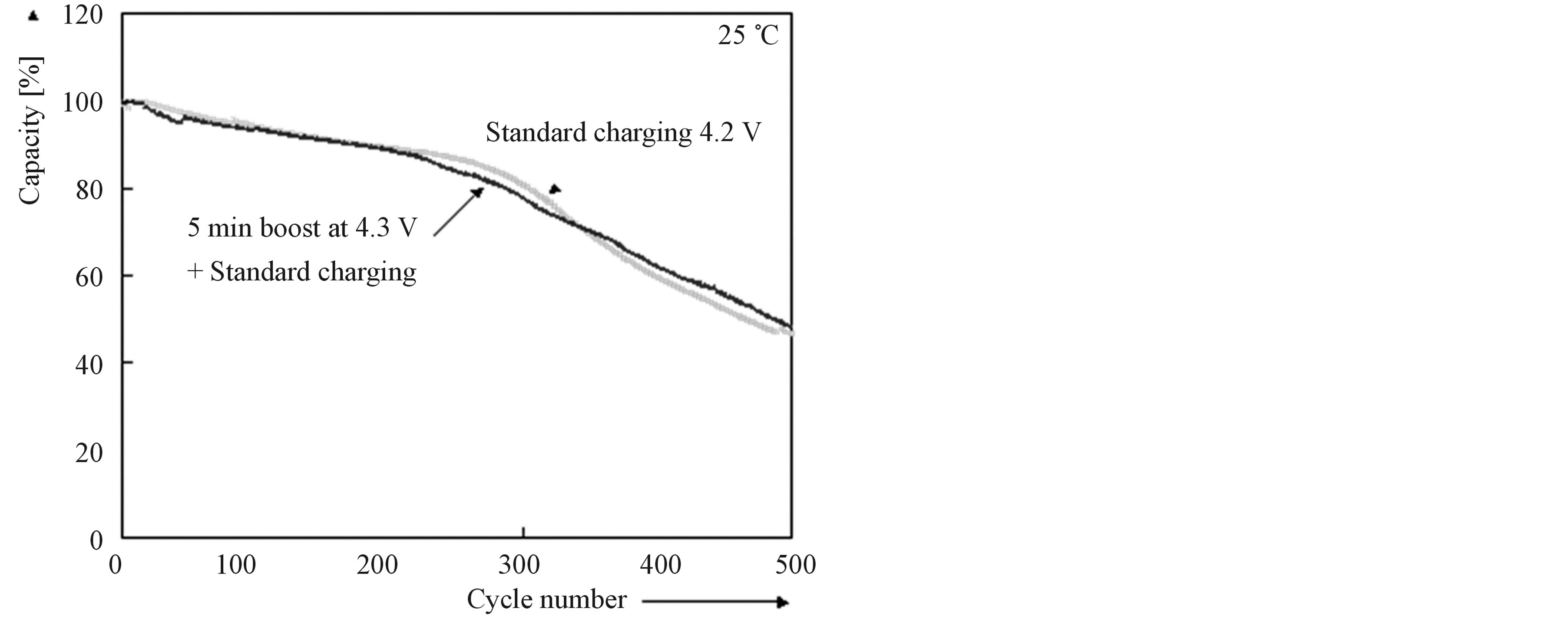
Figure 15. Effect of boostcharging on cycle-life for cylindrical (Sony) Li-ion batteries.
Charge. At low State-of-Charge even very high C-rates (8 - 10) are harmless for modern Li-ion batteries which makes “boostcharging” very attractive for application in PEV.
8. Conclusion
Advanced Battery Management Systems (BMS) can significantly improve the performance of many battery powered applications such as PEV and HEV. It has been shown that mathematical modeling is an efficient tool to understand the performance of rechargeable batteries and this insight subsequently can be used to improve BMS. An example related to boostcharging has been shown to be feasible, which facilitates ultra-fast and safe charging algorithm. It has been shown that a significant gain in charging rate can be obtained without imposing significant deterioration of the battery cycle life. The combination of advanced charging algorithms and adaptive BMS improves the battery performance and safety for many portable applications including electrical vehicles.
Acknowledgements
The authors appreciate the financial support from the ENIAC and EU Commission BattMan (contract 834720) and Dutch Powertrain (AutomotiveNL) projects.
REFERENCES
- M. Armand and J.-M. Tarascon, “Building Better Batteries,” Nature, Vol. 451, 2008, pp. 652-657. http://dx.doi.org/10.1038/451652a
- P. H. L. Notten, F. Roozeboom, R. A. H. Niessen and L. Baggetto, “3-D Integrated All-Solid-State Rechargeable Batteries,” Advanced Materials, Vol. 19, No. 24, 2007, pp. 4564-4567. http://dx.doi.org/10.1002/adma.200702398
- A. Ledovskikh, D. Danilov, W. J. J. Rey and P. H. L. Notten, “Modeling of Hydrogen Storage in Hydride-Forming Materials: Statistical Thermodynamics,” Physical Review B, Vol. 73, Article ID: 014106. http://dx.doi.org/10.1103/PhysRevB.73.014106
- P. H. L. Notten, W. S. Kruijt and H. J. Bergveld, “Electronic Network Modeling of Rechargeable Batteries II. The NiCd System,” Journal of The Electrochemical Society, Vol. 145, No. 11, 1998, pp. 3774-3783. http://dx.doi.org/10.1103/PhysRevB.73.014106
- A. Ayeb, W. M. Otten, A. J. G. Mank and P. H. L. Notten, “The Hydrogen Evolution and Oxidation Kinetics during Overdischarging of Sealed Nickel-Metal Hydride Batteries,” Journal of The Electrochemical Society, Vol. 153, No. 11, 2006, pp. A2055-A2065. http://dx.doi.org/10.1149/1.2336993
- A. Ayeb and P. H. L. Notten, “The Oxygen Evolution Kinetics in Sealed Rechargeable NiMH Batteries,” Electrochimica Acta, Vol. 53, No. 19, 2008, pp. 5836-5847. http://dx.doi.org/10.1016/j.electacta.2008.03.023
- H. J. Bergveld, W. S. Kruijt and P. H. L. Notten, “Electronic-Network Modelling of Rechargeable NiCd Cells and Its Application to the Design of Battery Management Systems,” Journal of Power Sources, Vol. 77, No. 2, 1999, pp. 143-158. http://dx.doi.org/10.1016/S0378-7753(98)00188-8
- H. J. Bergveld, W. S. Kruijt and P. H. L. Notten, “Battery Management Systems—Design by Modeling,” Vol. 1, Kluwer Academic Publishers, Boston, 2002. http://dx.doi.org/10.1007/978-94-017-0843-2
- D. Danilov and P. H. L. Notten, “Adaptive Battery Management Systems for the New Generation of Electrical Vehicles,” IEEE Vehicle Power and Propulsion Conference, Dearborn, 7-10 September 2009, pp. 317-320.
- A. Ledovskikh, E. Verbitski, A. Ayeb and P. H. L. Notten, “Modelling of Rechargeable NiMH Batteries,” Journal of Alloys and Compounds, Vol. 356-357, 2003, pp. 742-745. http://dx.doi.org/10.1016/S0925-8388(03)00082-3
- D. Danilov, R. Niessen and P. H. L. Notten, “Modeling All-Solid-State Li-Ion Batteries,” Journal of the Electrochemical Society, Vol. 158, No. 3, 2011, pp. A215-A222. http://dx.doi.org/10.1149/1.3521414
- D. Danilov and P. H. L. Notten, “Mathematical Modelling of Ionic Transport in the Electrolyte of Li-Ion Batteries,” Electrochimica Acta, Vol. 53, No. 17, 2008, pp. 5569- 5578. http://dx.doi.org/10.1016/j.electacta.2008.02.086
- V. Pop, H. J. Bergveld, D. Danilov, P. P. L. Regtien and P. H. L. Notten, “Battery Management Systems: Accurate State-of-Charge Indication for Battery-Powered Applications,” Springer, Dordrecht, 2008.
- D. Danilov and P. H. L. Notten, “Ageing of Li-Ion Batteries: Mathematical Description,” 2007th ECS Meetings, Quebeck, 15-20 May 2005.
- D. Danilov and P. H. L. Notten, “Theory and Simulation of Lithium-Ion Batteries: From Single Cycle Performance to Long-Term Aging Effects,” The 13th European Conference on Mathematics for Industry, Eindhoven, 21-25 June 2004.
- D. Danilov and P. H. L. Notten, “Variable-Rate Capacity Degradation Model for Li-Ion Batteries,” XII International Workshop on Lithium Batteries, Nara, 2004.
- V. Pop, H. J. Bergveld, P. P. L. Regtien, J. H. G. Op het Veld, D. Danilov and P. H. L. Notten, “Battery Aging and Its Influence on the Electromotive Force,” Journal of The Electrochemical Society, Vol. 154, No. 8, 2007, pp. A744- A750. http://dx.doi.org/10.1149/1.2742296
- P. H. L. Notten, D. Danilov and B. Op het Veld, “Adaptive Battery Modelling: A Challenging Route towards Sophisticated Battery Management Systems,” IMLB 2006 —International Meeting on Lithium Batteries, Biarritz, 19-23 June 2006.
- P. H. L. Notten, J. H. G. Op het Veld and J. R. G. van Beek, “Boostcharging Li-Ion Batteries: A Challenging New Charging Concept,” Journal of Power Sources, Vol. 145, No. 1, 2005, pp. 89-94. http://dx.doi.org/10.1016/j.jpowsour.2004.12.038
NOTES
*Corresponding author.