International Journal of Geosciences
Vol.4 No.1(2013), Article ID:27020,20 pages DOI:10.4236/ijg.2013.41009
A Review of Some Experimental Spray Methods for Marine Cloud Brightening
Fund for Innovative Climate and Energy Research (FICER), Sunnyvale, USA
Email: armandn@sbcglobal.net
Received September 21, 2012; revised October 24, 2012; accepted November 22, 2012
Keywords: Marine Cloud Brightening (MCB); Cloud Condensation Nuclei (CCN); Taylor Cone-Jet
ABSTRACT
Marine Cloud Brightening (MCB), should it ever need to be deployed, envisions the formation of 1017 salt Cloud Condensation Nuclei (CCN) per second coming from each of several thousand vessels deployed worldwide. The creation of this many nuclei on such a vast scale, from micronor submicron-sized seawater droplets, preferably mono-disperse, poses a considerable engineering challenge. Various existing or experimental spray methods were investigated for feasibility, resulting in the identification of a few with promising results. Electro-spraying from Taylor cone-jets, using either silicon micromachined long capillaries or short capillary polymer substrates attached to a porous substrate, appears to have the best potential for implementation of all the methods that have been investigated so far.
1. Introduction
This paper summarizes the results of a number of research experiments that we have carried out to produce a very fine spray of seawater that might be suitable for the Marine Cloud Brightening (MCB) geo-engineering method [1-3]. The technique proposes to counteract the thermal (and regrettably, only the thermal) effects of climate disruption by increasing the world-wide cloud albedo of marine boundary layer clouds by introducing artificially formed salt nuclei into these clouds.
The goal was to identify a spray system that could conceptually provide roughly 1017 Cloud Condensation Nuclei (CCN) per second from a single seafaring vessel. Assuming no coalescence, and no significant disintegration of droplets once formed, this would mean the initial creation of an equal number of droplets per second. The formation of such fine sprays implies, at its minimum, creation of the surface energy associated with the increase in surface area when the liquid is dispersed. Most methods require considerably more energy than this minimum, but because over its lifespan a cloud droplet reflects many million times the energy needed to create it, the MCB method remains very energy efficient. While we attempted to minimize the required energy in each approach, the primary research goal was to develop a working method suitable for scientific cloud experimentation, regardless of energy cost.
As envisioned by Salter et al. [3], this method would spray from each vessel about 30 L/s of sea water in droplets 0.8 µm in diameter, yielding 1017 nuclei per second. Worldwide, 4.5 × 10⁴ kg/s of seawater would need to be dispersed. Preferably, to be most effective, the nuclei formed should be monodisperse or of narrow size distribution [3].
It is not the amount of sprayed water that is important, but the number of suitable nuclei that are formed. Each suitable nucleus, above a certain minimal salt mass will create a droplet many times its original size when converted in the cloud. The critical requirement is that the salt mass, ms, be high enough that it can convert into cloud droplets at supersaturations S occurring in marine stratocumulus clouds. S depends on updraft speed, and the properties of the air mass. Cloud modeling has provided values of this critical mass for a variety of relevant scenarios. They show that significant droplet formation and its associated cloud albedo increase can occur for salt masses down to about 5 to 7 × 10-20 kg [4]. This would correspond to dry salt cubes 28 to 32 nm on edge (35 to 40 nm equivalent sphere diameter), and to sprayed seawater droplets on the order of 140 to 160 nm in diameter (a factor of four reduction in diameter occurs when seawater droplets of 3.6% salt concentration evaporate).
For maximum energy efficiency, it is of course advantageous to make the droplets as close as possible to this lower acceptable limit, thus limiting the amount of liquid that needs to be sprayed and the associated spray production energy.
There is believed to be a significant secondary benefit. The smaller the amount of liquid sprayed, the smaller the negative buoyancy created by the evaporation of sprayed droplets, which might possibly inhibit their vertical ascent. The intense concentrated spray, i.e. 30 L/s envisioned in some MCB implementations, and its associated concentrated cooling, may inhibit the buoyancy required for the nuclei to reach the marine boundary layer even when using a considerable forced air launch (10 m/s). Artificial cloud formation using water spray over land has been a commercial goal for a long time for various special effects in movies, TV commercials, etc., but it has never been achieved [5]. Even when substantial updrafts are used, invariably the result is a low-hanging fog, a consequence of the intense localized evaporative cooling. Simple engineering calculations confirm these effects. While the negative buoyancy created by evaporative cooling is not exactly proof that the approach will necessary fail over the ocean, where a different set of updraft and wind conditions exist, we have eventually concentrated on methods that do not suffer, or at least suffer much less, from this potential difficulty, mainly because in general we spray much less water to get the same number of particles.
For completeness we will describe all of the techniques that have been investigated, including those that failed to achieve the desired result. Currently we are investigating the spraying of saltwater at or near critical conditions, with initial results that are very promising. These results will be presented in a different publication.
2. Results and Discussion
2.1. Use of Commercial Nozzle Sprayers
At the outset of the investigation we investigated, as a starting point, the performance of a number of standard commercial nozzles (Mee Industries, Bete, Steinen) used in fogging systems. The purpose was to see if these nozzles and the particle size distributions they produced could be scaled down by micro-machining. A Malvern Spraytec model RTS5114 particle size analyzer (courtesy of Mee Industries, Inc.), calibrated using lithographically defined targets (courtesy of D. Hirleman, Purdue University), was used to analyze the spray. The nozzles were fed from a high pressure vessel (Parr Instruments 4601) pressurized with nitrogen. This pressurization produces a significant amount of dissolved gas at high pressure, with subsequent expansion upon spraying. However, it is believed that the nozzle operation was not significantly affected by these differences, although gaseous desolvation, if used properly, can reduce the particle size distribution of sprays (as observed with effervescent spray nozzles).
Impact spray nozzles supplied to us by Mee Industries, by far the best-documented fog nozzles, operated at 6.9 MPa (1000 psi), produced droplets with a Sauter Mean Diameter of 15 µm (somewhat larger than that reported by Chaker) [6]. The Sauter Mean Diameter (SMD, d32) is defined as the diameter of a drop having the same volume to surface ratio as the entire spray. These nozzles direct a high speed jet (150 µm diameter) toward an impact pin, where a conical spray cone is formed. Figure 1 shows the results for a Mee Industries nozzle measured with the Malvern Spraytec. It is typical of the results for all commercial nozzles tested. A further increase in pressure produces only a marginal decrease in the droplet size.
These nozzles form rapidly moving, thin, conical liquid sheets, whose interaction with air leads to a pressure-driven radial instability creating broken up flat rings [7,8]. The breakup mechanism described is as follows: any perpendicular perturbation on the sheet creates a
Figure 1. Particle size distribution from a Mee Industries nozzle as measured with the Malvern Spraytec showing both particle size and the cumulative mass distribution.
pressure excursion (as in an airplane wing), thereby amplifying itself and creating breakup into flat rings at some optimum wavelength. Surface tension then contracts these flat rings into thin toroids. The toroid subsequently breaks up longitudinally according to the Rayleigh jet criterion [9]. In contrast to Rayleigh jet breakup, the size distributions formed are far from monodisperse, so that the theory is at best a rough approximation. Further drop breakup may occur through turbulent air interaction, depending on the velocity of the spray.
If the liquid sheet was as thin as 1 µm, one would end up with droplets as large as 10 µm if no further turbulent breakup occurs [7]. In order to produce the desired droplet size, extreme miniaturization would be needed.
More elaborate nozzles, such as the effervescent spray nozzle [10], which use a mixture of fluid and compressed air, are capable of producing sprays with 2.5 µm diameter droplets. This would require the spraying of almost 900 kg of water per second to achieve the required nuclei count and would produce significant air cooling.
2.2. Toroidal Cone Sprayer with Electrical Charging
Inspired by a design for a very high power water-cooled X-ray lithography tube [11], a special conical nozzle with a toroidal cone (see Figure 2) was designed. The purpose was to create a liquid sheet in a form that can be highly charged so that additional disintegration of the droplets may be accomplished electrically by Coulombic fission (the electrodes, not shown in Figure 2, surround the cone exit).
In this device a jet is projected onto a curved conical cusp. The curved cusp produces very high centripetal acceleration (approaching 400,000 g), pinning and thinning the liquid along the cone surface. Because of this guiding the liquid can thin without premature break-up. At the cone exit, electrical charging can be applied to the emerging liquid sheet, with the aim of producing further
Figure 2. Toroidal Sprayer before assembly of the electrodes. The liquid thins along the cone, pinned by centrifugal forces, producing a very thin exit sheet.
droplet disintegration during evaporation. In principle the emerging thin flat liquid sheet lends itself very effecttively to induction charging from planar conical electrodes.
The toroid was designed to gradually thin an initial liquid annulus 100 µm in thickness to 1 µm thickness at the cone exit. Experiments showed that the sheet slowed down significantly before reaching the cone exit. Modeling the flow along the toroid showed that as the liquid sheet thickness approached the boundary layer thickness, excessive friction losses would overtake and slow the flow down.
The use of graphite air bearing technology for the cone, to reduce friction, was considered. But because uncharged liquid sheets even at 1 µm thickness will produce 10 µm droplets, redesign for exit thickness greater than the boundary layer, or using boundary layer thinning techniques was not pursued. As will be shown, even charging would not produce the desired result.
If the emerging droplets are highly charged and evaporate, they could potentially reach the Rayleigh droplet stability limit where electrical pressure overcomes surface tension [12,13]. Mother droplets will then eject charged daughter droplets through the emergence of two opposing Taylor cone-jets, until the electrical pressure is significantly less than the surface tension for the parent droplet [14]. The ejection carries a relatively large amount of charge, but relatively little mass, and is self extinguishing [15,16]. By a fortuitous coincidence, given the high conductivity of seawater, these daughter droplets are very small, close to the desired range, with a size independent of that of the generating droplet [17]. The process repeats itself as the evaporation of the parent droplet proceeds. In principle this would go on until all droplets are completely dispersed (or solidified).
Unfortunately, the amount of charging that can be produced is not sufficient to create instant Rayleigh disintegration of the droplets and produce daughter nuclei by droplet fission. Hence, we expect that we would need to rely on substantial evaporation before this could happen. Analysis shows that charging a 1-µm thick liquid seawater sheet (on both sides) with fields approaching electrical breakdown in air at the electrodes, does not produce enough charge to ever produce droplet fission. At the level of charge that can be imposed, and as the droplets contain 3.6% salt, droplets would crystallize after shrinking by a factor of four in radius before ever reaching the Rayleigh limit. Hence splitting could not occur unless some other process took place.
2.3. Colliding-Jets Spraying
Suggestions have been made by various authors [3,18] that the head-on collision of two jets might produce more intense and finer atomization. Intuitively, a symmetric collision might be expected to channel more of the energy of the incoming jets into disruptive energy (being a center of mass system) and might produce droplets of smaller diameter.
What is observed experimentally is that if the two identical emerging jets have not broken up before collision, they fuse to form a perpendicular moving radial liquid sheet, just as if each one of them were to hit a solid surface [19]. This free-standing radial moving liquid sheet itself then breaks up as described previously for the liquid sheets from fogging nozzles, but as it has twice the sheet thickness, it actually ends up producing larger droplets. Figure 3 shows a picture of the colliding jet experiment. It was found that the jets need to be slightly angled to each other to produce a stable intersection, as the intersection is otherwise indeterminate.
It might be surmised that if the jets were fully broken up before collision, individual droplets might be ex-
Figure 3. Colliding Jet Experiment. Under a pressure of 70 bar the jets are emanating at a velocity of 60 m/s, and are 1.4 mm in diameter. The radially moving sheet can (barely) be seen at the intersection of the jets.
pected to collide with the desired effect. However the jets do not disperse rapidly, in spite of the fact that they are saturated with dissolved nitrogen at 6.9 MPa from the driving pressure. In an attempt to produce explosive desolvation of the absorbed gases in the jets, high intensity ultrasonic energy at 30 kHz from the horn of a cell disrupter (Branson Sonifier 450) was applied to the exit nozzles. This created a marked change in the exit appearance of the jets, but the sprayed droplet distribution of the colliding jets was not measurably improved. Figure 4 shows a typical Spraytec result for the droplet distribution of the colliding jets of Figure 3. These distributions are unsuitable for MCB work.
2.4. Ultra-High Pressure Jet Spraying
Increasing the driving pressure of a jet and decreasing surface tension can in principle decrease the droplet distribution size. Experimentally it is well established that some diesel injectors operating at 13.8 MPa (2000 psi) produce 2-µm droplets [20].
The average particle size emerging from a diesel injector nozzle follows the following scaling laws of Equations (1) and (2) [20]:
 (1)
(1)
where:
 (2)
(2)
SMD = Sauter mean diameter
σl = surface tension of the liquid
μl = dynamic liquid viscosity
ρl = liquid density Vl = injection velocity
Figure 4. Spraytec results from colliding jets: pressure 6.9 MPa (1000 psi), 1.4 mm jet diameter, jet velocity 60 m/s.
ρg = gas density Pl = liquid pressure Pg = gas pressure Cv = orifice flow coefficient Briefly, reducing the liquid’s surface tension, increasing the driving pressure and, to a smaller degree, reducing the liquid’s viscosity and density all reduce the droplet size. The exponents for density and viscosity dependence are small (0.1, 0.5). The formula suggests an almost inverse linear dependence on the driving pressure.
Compact, mass-produced and relatively inexpensive pumps for water-jet cutting machines can now achieve over 600 MPa, and have flow rates on the order of 90 mL/s. Thus, if the sprayed droplet size distribution were to be well into the submicron range, only a modest number of jets per ship would be required.
We tested the plume of a jet emanating from a waterjet cutting machine, operating at 344.7 MPa (50,000 psi) without the cutting grit present, at the Monterey Bay Aquarium Research Institute (MBARI) [21]. Because the jet is oriented vertically for cutting purposes and could not be reoriented horizontally for the experiment, it was deflected off a flat carbide tool oriented at 45˚. The carbide tool was positioned close enough to the jet so that there was no visible jet breakup before bouncing off the tool.
Experimentally, very broad distributions (10 to 250 µm) were observed in the plume of the jet, rather than the small particles that had been hoped for. Figure 5 shows the MBARI experiment in operation and Figure 6 shows the Spraytec results. It can be seen that the plume, given its 45˚ launching rises inside the warehouse, but levels off and stops rising before full evaporation.
There are very few, if any, submicron particles to be seen in the measured distribution. (It should be noted that even if they had been present, such particles could not be measured with the instrument in use.) However, if they had been present in copious amounts one might have expected a bulge in the lower end of the spectrum. Such a signal was, however, not observed in any of the histograms.
No surfactant was used. It would have been advantageous to introduce the surfactant in the port where cutting grit is normally supplied thereby surrounding the surface of the emerging jet, but this was not performed.
The nozzle for this water jet cutting device is, of course, specifically designed for jet formation, not dispersion. A more appropriate design might have produced results more in line with expectations from the theory.
2.5. Rayleigh-Jet Spraying through Small Apertures
In terms of droplet uniformity, and also from an energy view point, the most efficient way to produce narrow

Figure 5. MBARI jet experiment with a 344.7-MPa jet.
Figure 6. Spraytec results obtained at MBARI from a 344.7-MPa (50,000 psi) jet.
particle size distributions is to create an array of sprays using acoustically controlled Rayleigh-mode jet breakup [9]. Provided all the jets are of the same size, and with suitable precautions such as perpendicular airflow and appropriate charging to inhibit the coalescence of the resulting drops, very narrow distributions with only a few percent droplet coalescence can be obtained [22].
To generate the 0.8-µm diameter droplets as proposed by Salter et al. [3] would require apertures on the order of 0.5 µm in diameter. Historically, suitable small holemaking was the difficult part of the technology. In the last decade there has been great technological progress in the fabrication of small holes in silicon using the Bosch etching process, achieving spectacular hole aspect ratios (>50). Because of the need for through-silicon wafer “vias” (TSV), even standard etchers have lately achieved remarkable results, and this technology has entered not just micromachining, but mainstream silicon manufacturing.
The main problem with this approach is therefore no longer the formation of small holes, but keeping them open while spraying over extended periods without clogging. Clogging is a poorly understood process and may have both chemical (reactive film deposition) and physiccal (particulate obstruction) components to it. A generally accepted rule of thumb in spraying is that no particles larger than one tenth of the spray aperture diameter should be present in the fluid to be sprayed. Techniques such as periodic backflow may be used to flush out debris and extend the lifetime [3].
The holes should have minimum flow impedance for minimum clogging and low power requirements. Optimum holes have a roughly conical shape, with the apex at the exit, so as to produce a significant vena contracta, further reducing the exit jet diameter and requiring minimal pressure across the aperture for a given jet diameter.
To produce flow through small holes over an extended period, we have found it strictly necessary to employ the fluid filtering system shown in Figure 7.
The fluid to be sprayed is first circulated and filtered continuously in its closed loop for an extended period of time (12 - 24 h) before spraying.
We were able to spray continuously for 140 h (20 L) through square, 5-µm, anisotropically etched holes in silicon, using a 0.5-µm filter followed by a 0.2-µm final filter just in front the apertures. Without the pre-filtering operation, clogging was disappointingly fast (a matter of seconds). No back flushing (to remove accumulated debris) of the aperture was used in this experiment. While the target 0.5-µm hole is 10 times smaller in diameter (100 times in cross-section), this result encouraged us to attempt the fabrication of much smaller holes.
An ideal substrate for spray aperture fabrication would
Figure 7. Saltwater filtering system using continuous recirculation before spray.
be a titanium foil, 12 µm thick. Nearly corrosion-free and not brittle, Ti lends itself both to wet and dry etching. The foil can be formed into a spherical shape, thereby providing angularly divergent jets, which should help to avoid coalescence of the sprayed particles. Entrainment and pumping of air causes collinear jets in dense arrays to collapse towards each other, resulting in significant coalescence.
Through cooperation with, and a grant from, the Stanford Nanofabrication Facility the fabrication of 0.5-µm holes in 12-µm thick titanium membranes was undertaken. Ti membranes supported by silicon wafers were patterned both with e-beam and contact projection lithography. However, wet etching (producing hemispherical etch pits) could not achieve the desired resolution. Although dry etching could very likely achieve the desired geometries, the Si etching equipment at the facility could not be used with Ti because of the ensuing silicon contamination issues in the etcher. The fabrication of these Ti holes was therefore given lower priority until the issue of 0.5-µm hole-clogging could be resolved.
Hence it was decided to use as a substitute the holes in commercial radiation-track filters, well known in biological research. These filters have holes in polycarbonate membranes, created by alpha particle tracks that are subsequently chemically etched, are remarkably uniform and well controlled and are therefore used as absolute filters (see Figure 8). They are inexpensive and commercially available from a variety of manufacturers (e.g., Whatman Corp.).
The cylindrical hole shape provides for a large viscous resistance, and over 3 MPa of pressure would be required to produce the jet velocity required for Rayleigh spraying. This is well outside the operating parameter region of our present filter system. Because of the thinness of these unsupported flexible membranes (8 - 10 µm), and the high pressure required by the cylindrical holes, fully formed free jets could not be drawn out of this arrangement.
Therefore we could only operate the system near its maximum pressure, producing only a seeping flow through the holes, which was measured over time, presumably giving an estimate of the clogging rate of the holes. The seepage rate decreased by an order of magnitude over 350 h, indicating prompt clogging of the 0.6-µm holes at low flow rates.
Figure 9 illustrates the measured inverse flow rate (right) and total flow (left) as a function of operating time. The seawater had first been circulation-filtered for 8 h through a 0.05-µm filter to remove all possible debris before actual “spraying” was started.
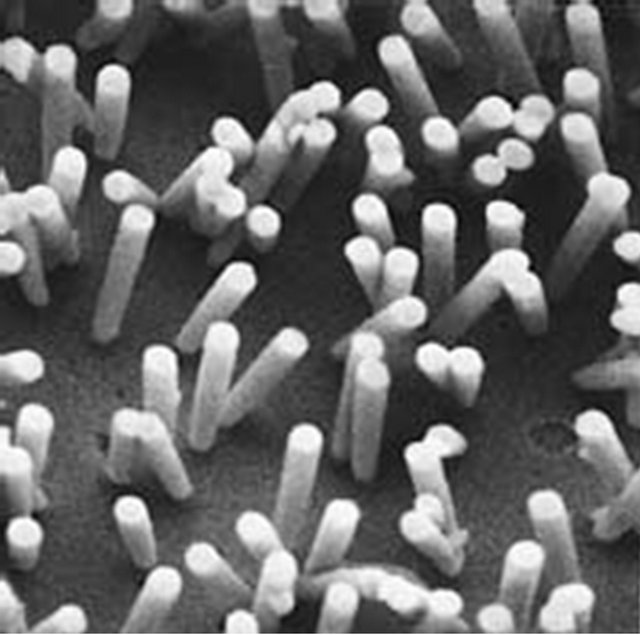
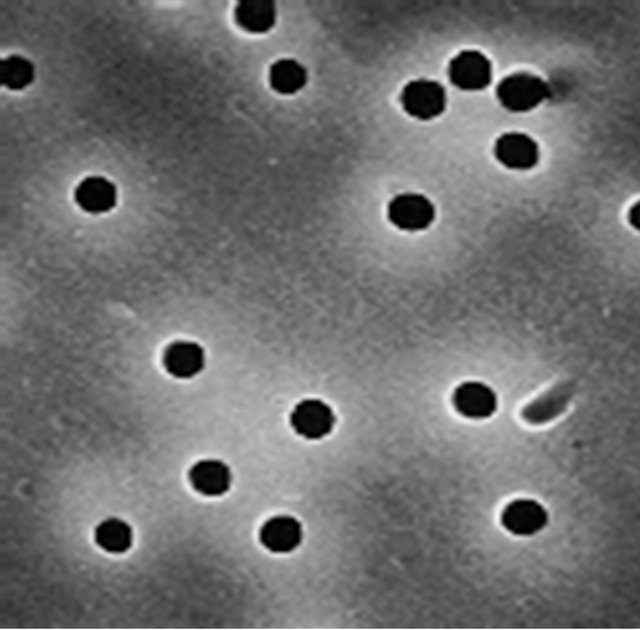
Figure 8. SEM pictures of 0.6-µm diameter holes in a 10-µm thick polycarbonate membrane (Whatman Corp.). Hole location is random and hole density is controlled by radiation dose. The uniform profile of the hole in the film can be inferred from the microcasts, seen on the right.
The discontinuities and flow improvements observed at 400 h occurred when the final filter (0.05 µm) in front of the spraying holes was replaced. The gradual decrease in flow rate indicates hole clogging, even at the much reduced flow rates that were employed. We briefly evaluated improved filtration arrangements and components in an attempt to remedy this situation, but results were not encouraging.
The holes that were used here are of very high aspect ratio, made of one particular material (polycarbonate), and operated at a very low flow rate. The clogging behavior may possibly be characteristic of this particular set of experimental details. In fact, the clogging may be partially chemical in nature, rather than caused by physical obstruction by particulates. Since, in addition, backflow (reversing the flow to remove debris) was not used in any of these experiments, the results are not definitive. However, this approach looks difficult to implement.
It should be kept in mind that spraying from many jets simultaneously is a somewhat “brittle” solution. The creeping flow from a partially clogged jet (and the associated salt deposition) usually spreads and affects the operation of the other jets around it, often bringing the assembly to failure.
2.6. Electro-Spraying from Cone-Jets with Air-Assist
2.6.1. General Description
The phenomenon of electrospray, first observed by Zeleny [23] and described in detail by Taylor [24] is now extensively used in mass spectroscopy. Arrays of Taylor cone-jet capillaries are also used as micro-thrusters for satellites [25,26]. The most interesting electrospray mode is the cone-jet, i.e., a liquid cone ending in a continuously emerging jet. This outcome is usually obtained by imposing a fixed flow rate to a capillary containing a fluid (either conductive or insulating) with simultaneous
Figure 9. Total flow volume (left) and inverse flow rate (right) as a function of time.
application of an electric field to the capillary tip. Under the right experimental conditions, the size of the jet that emerges from the cone is independent of the capillary size, and its diameter is defined mostly by the properties, such as conductivity and surface tension, of the sprayed fluid. The more conductive the fluid, the smaller the jet, as illustrated by the fact that liquid metals give rise to single-ion sprays.
Fortuitously, the conductivity of seawater (~4 S/m) is such that the spraying of seawater from cone jets (emanating either from droplets or capillaries) produces droplets in the right range for application to cloud brightening. The size of the droplets sprayed would be so small (100 - 200 nm diameter) that only a few tenths of a liter of seawater would need to be dispersed per second in order to meet the 1017 particles/s requirement.
The cone shape first described by Taylor [24] defines a region where the electric field and the surface tension are in quasi-equilibrium. Hence, knowing the radius of curvature of the cone allows the determination of the electric field at the surface. The description of the emerging jet itself is much more complex, particularly for high-conductivity liquids such as seawater. Analysis by De la Mora [27] and Gañán-Calvo et al. [28] suggests that the conductivity of the liquid determines a critical cone radius (ri), defined such that the ratio of the volume of the cone, from this radius to the apex, divided by the imposed flow rate, is equal to the dielectric relaxation constant of the fluid. A highly charged jet of approximate radius 0.2 ri (depending on the theory) emanates from the cone and breaks up in a tight fashion similar to that of an uncharged Rayleigh jet. It is this phenomenon that gives rise to the remarkably narrow droplet size distributions that may be achieved by this technique. For such highly charged jets, each drop is often accompanied by a satellite drop having a radius one half to one third of that of its parent drop, resulting in a bimodal spray distribution. As the volume of the satellites is much smaller, their contribution is insignificant, particularly for CCN formation as these would probably not convert into droplets under the observed cloud supersaturation values.
Figure 10 shows a Taylor cone in operation, spraying 3.5% saltwater from a porous pen tip, rather than the usual solid tubular capillary. The use of a porous cone support, rather than the classic capillary, experimentally appeared to facilitate the stability and ease of formation of the cone. The liquid cone is the small transparent section visible at the end of the pen. The jet emanating from the cone, and the resultant droplet spray, are invisible, being of sub-micron dimension (approx. 150 nm in diameter). However, illumination with a green laser-pointer can make the spray visible, a situation that was found to be helpful in establishing the optimal spraying conditions.
Figure 10. A single Taylor cone drawn from a porous pen tip. The cone is the transparent liquid at the tip; the jet and resulting spray are invisible, the jet being about 150 nm in diameter.
The droplet spray is directed towards the anode, typically a silicon wafer that can later be inserted into a Scanning Electron Microscope (SEM) for examination of the spray residue. Upon drying, a 3.5% salt solution droplet will give rise to a salt crystal that is approximately four times smaller in size. For reference, the desired minimum salt-mass of 7 × 10⁻²⁰ kg corresponds to a salt cube 32 nm on an edge.
Figure 11 shows SEM images, at different magnifications, of salt particles produced by a Taylor cone emanating from a porous tip as in Figure 10 (3.5% salt concentration), collected on a silicon wafer 2 cm away at a 5.4-kV potential, a current of 0.2 µA, a flow rate of 5.6 nL/s, using 540 ppm of surfactant (Triton X-100; the role of the surfactant will be explained below). The average size of these (approximately) cubic crystals is on the order of 60 nm, well above the desired threshold, but satisfactory for the intended purpose.
Figure 12 shows a histogram of salt particles deposited under similar conditions, in this case with an average size of 82.6 nm (equivalent sphere diameter). The tight distribution is characteristic of the Rayleigh jet breakup method of production.
Salt crystals similar to those of Figure 11, positioned on a silicon wafer, were readily activated at a supersaturation of 0.5%, achieved by cooling the wafer with a thermo-electric chuck in a controlled saturated vapor environment. Since the surfactant surface concentration is extremely low after dispersal, no noticeable effect on conversion was expected or observed.
The droplets appear to have evaporated completely before they reached the silicon wafer two cm away. This conclusion of near instantaneous evaporation is based on the experimental observation that dense spraying results
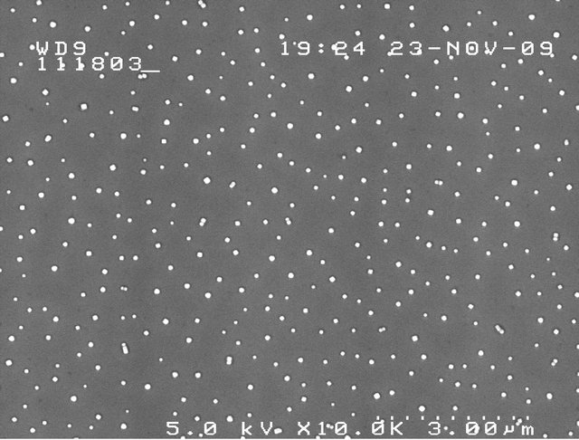
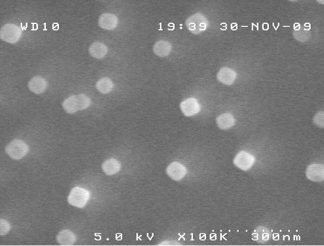
Figure 11. SEM images of salt particles sprayed from 3.5 wt% saltwater cone-jets at different magnifications (10 K and 100 K). The average size of the particles is 59.8 nm.
Figure 12. Particle size distribution from a felt tip Taylor cone, fitted to a log-normal distribution. The mean particle size is 82.6 nm (equivalent sphere diameter), with a Geometric Standard Deviation (GSD) of 1.19.
in clusters of individual salt crystals, as illustrated in Figure 13, rather than the larger single crystals that would result from coalescence before evaporation.
Given a separation of 2 cm between the cone and the electrode, and droplet velocities of several hundred meters per second, the evaporation time would seem to be less than 10−4 s. This almost instantaneous evaporation of the droplets is due to their small size, their emergence from the jet with velocities approaching the speed of sound, and perhaps the heating that takes place in the cone itself [29].
Cone-jet heating occurs mainly with very conductive liquids (such as seawater) and can affect fluid properties such as surface tension, and can increase evaporation from the cone (which would affect the accuracy of cone flow measurements). The Crowley model predicts near boiling temperatures for the conditions that were used, but this static model does not include circulation and convection at the tip [30], and hence probably overestimates the temperature rise. Experimentally, it is easy to observe the formation and circulation of gas bubbles at
Figure 13. Observation of superposed salt crystals on dense spraying. The fact that distinct crystals can be seen indicates that salt particles are mostly dry upon arrival.
the tip end at high currents, indicative of the onset of boiling.
Rapid droplet evaporation may provide a somewhat unexpected, but perhaps crucial, benefit to Taylor conejet spraying. As the droplet is almost instantly fully evaporated, no further evaporation with its associated air cooling needs to take place. This, together with the low required volume of liquid sprayed (200 - 600 mL/s) minimizes the air cooling. It might be expected that these crystals would rise rapidly with the prevailing updraft over the ocean without affecting the existing atmospheric conditions.
The experiments described above were performed repeatedly, with repeatable outcomes. However, our experimental results are not in agreement with what would be expected according to the current theories for very conductive liquids. In fact, according to these theories, spraying of a high conductivity liquid such as seawater (K ~4 S/m) at the rate 5.56 nL/sec would result in a current of 2.3 µA with borderline stability, producing 1.6 × 10¹⁰ droplets per second comprising salt masses of 1.2 × 10⁻²⁰ kg—too small for application to cloud whitening.
A critical re-examination of the data showed that the felt pen tips, while easy to set up, exhibited some severe deficiencies in operation. As the liquid area exposed is large, as compared to the minute cone-jet itself, the evaporative flow from the wetted surface under normal lab humidity conditions may very much exceed the jet flow from the tip itself. Upon examination, during extended operation, deposits of crystallized salt were found at the periphery of the wetted porous tip surface. Hence the salt concentration in the liquid may have reached a much larger concentration than the initial 3.5%, thereby completely changing the spray parameters. To prove this point, the salt mass sprayed over an extended period to a thin Al foil electrode was measured, and found to be only 1% - 2% of that expected based on the total salt flow imposed on the tip by the syringe pump. This very small flow rate at the cone itself was then roughly reconciled with the observed current predicted by the theory, but the theory would still predict salt masses of less than 10−20 kg, clearly not in agreement with the observations. In all these experiments, surfactant was added to lower the surface tension so that the applied voltage could be kept below the breakdown voltage of air, thus preventing corona discharge.
To gain further understanding, the experiments were repeated using very small glass capillaries, supplied by Eppendorf. These extremely thin glass capillaries, used in the manipulation of individual cell contents, have an outside diameter of 20 µm, an inside diameter of 16 µm, and 2 µm wall thickness. This arrangement completely minimizes the cone evaporation surface. Both squareand beveled-end capillaries were investigated. The same surfactant (500 ppm of Triton X-100) was used as above. No corona emission was observed.
The results of spraying from these capillaries are illustrated in Figure 14. In spite of different conditions, these results indicate a mean particle size very similar to those illustrated in Figure 11 obtained using pen tip cones.
The mean distribution diameters observed ranged from 47.6 nm to 67.6 nm except for one sample that measured 105.4 nm, while GSD ranged from 1.54 to 1.86.
The experiments were repeated without surfactant for the same 3.5% salt solution. No corona discharge was observed in positive mode spray (capillary positive relative to target) from these fine capillaries. On a couple of occasions, distributions around 25 nm were obtained, but in general the sizes obtained were in the 50 nm range, with GSDs roughly similar to those obtained in the presence of surfactant.
Here again, the observed results are not what would be expected based on theory. Lopez-Herrera et al. [31] sprayed water from a 36-µm diameter (beveled) tip capillary. The sprayed fluids comprised deionized water, and the same doped with HCl to increase conductivity, including samples with conductivities of 1.8 S/m (the latter requiring a guard sheet of carbon dioxide to deter corona discharge). Their observed current flow measurements are in agreement with the theory of Gañán-Calvo, but droplet size was, unfortunately, not measured.
Our observed deviations from theory for saltwater, with or without surfactant, cannot be reconciled for the moment, but visual observation makes it clear that the
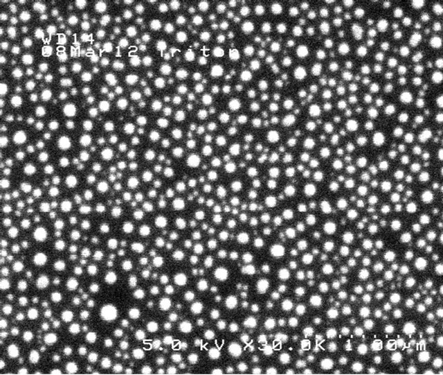
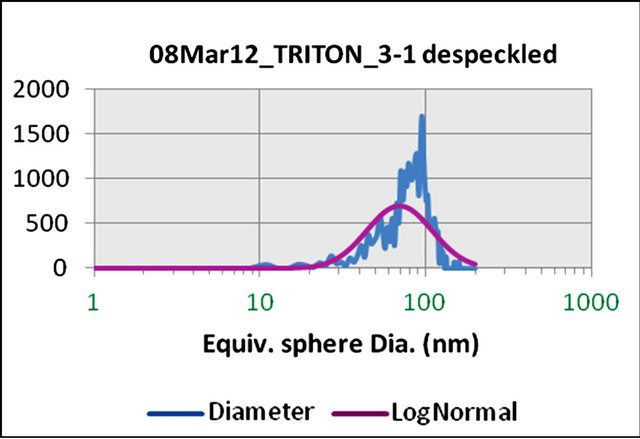
Figure 14. SEM image of salt particles, and their size distribution histogram, obtained by Taylor cone-jet spraying from glass capillaries at 3.4 kV and 1.8 µA and a flow rate of 3.3 nL/sec. The equivalent sphere mean diameter is 69.6 nm, with a GSD of 1.57.
precipitation of some salt around the cone has a dramatic effect on spraying and its behavior in general.
2.6.2. Air Breakdown-Free Operation
Historically, with high conductivity liquids having surface tensions greater than 50 mN/m, such as water, conejet spraying is, with few exceptions, very negatively affected by the presence of corona discharge. This not only increases the current (and power requirement) significantly, but the mono-dispersivity of the droplet distribution is dramatically compromised [32,33]. The addition of surfactant to water is found to eliminate corona discharge [34]. This follows readily as the threshold field for instability  is directly set by the surface tension
  for a given capillary diameter D. At the same time, surfactant lowers the emitted current [27]. Both of these effects reduce the power needed to spray. From an environmental point of view, the use of surfactants is undesirable, even though only about 1 L would be used in a 24-hour continuous spraying period. Conceptually at least, natural surfactants present in the ocean might be used.
However, in at least one of the physical implementations considered for scale-up (see below), any surfactant that has been added and tested so far has negative consequences, as nearly as can be determined. A corona-free operation without surfactant is highly desirable.
While the breakdown field of air is often listed as 3 V/µm for large objects, in fact it can be several orders of magnitude higher for submicron-sized electrodes [35]. Breakdown is mostly determined by the field strength and the path length needed for electrons to reach enough energy to ionize a gas molecule and start an avalanche. If the spatial extent of the energizing field is very small (such as around a thin wire) the total momentum and energy that can be obtained by the electron is very limited, and the breakdown field can approach 1 V/nm in air, i.e., an increase of almost three orders of magnitude.
For reference, Figure 15 shows the normal field of a Taylor cone-jet of water as a function of the cone radius, and the breakdown field in air for a cylindrical wire (or jet) as a function of its radius. The values for air breakdown are those listed by Cloupeau [32], after Rousse [35]. On a Taylor cone surface, the surface tension and electric field are in equilibrium, and knowing the radius simply defines the electric field from , i.e., the ratio of surface tension to the local radius of curvature.
This figure shows that a Taylor cone jet from seawater, if it has a radius anywhere larger than 10 - 12 µm (where crossover is seen to occur) will exhibit breakdown in air, which is indeed what is observed (there is some polarity dependence). This is also in accordance with the experimental observation that very small capillaries (20 µm inside diameter) can, on occasion, be used to spray pure water without corona discharge [31]. Capillaries smaller than 10 µm in radius should in principle produce no discharge in all conditions. Experimentally, dielectric capillaries work better than metal ones. The beneficial effect
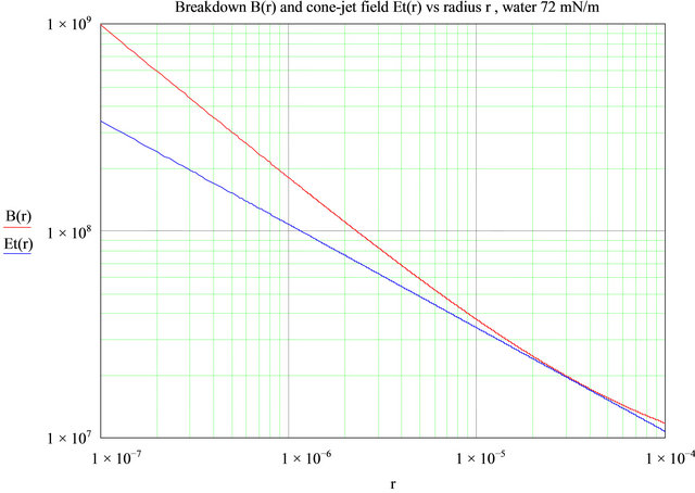
Figure 15. The field along a Taylor cone of seawater Et(r) (blue line), and the breakdown field in air B(r) (red line) for a conductive jet, versus its radius r. Where the red curve is above the blue curve, there is no breakdown or corona discharge. Field units are V/m.
of a surfactant can be seen in the next figure. Even at dilutions of 50 to 100 ppm, modern surfactants such as Triton X-100 or Tween 20 can drop the surface tension of water by a factor of two. This lowers the Taylor cone field proportionally and the net result is as shown in Figure 16. As can be seen, the air breakdown field limit is everywhere above the field on the cone, and no breakdown occurs, as is experimentally observed.
This simple analysis is not the whole story during dynamic operation—for a surfactant to be useful its must reach the free surface and disperse itself there.
Depending on concentration, this may take a millisecond. In the cone area of a cone-jet, where the surfactant is needed in order to be effective, the surfactant has plenty of time to diffuse to the surface and exercise its function. At the formation and breakup of the jet however, events probably occur so quickly as to make the surfactant ineffective.
Adding surfactant is one way by which the relative positions of the two curves can be affected. As seen in Figure 15, the two curves are quite close to each other, and minor changes to parameters that affect either one of them should prevent the onset of corona. Some of these changes will now be described.
Heating water to 90˚C, which requires little energy since little water is used here, reduces surface tension from 75 to 60 mN/m, which, as shown above, is beneficial. Another way to increase the breakdown field is to raise the ambient pressure, since breakdown voltage is proportional to pressure. Conducting the spraying in a chamber with an overpressure of 0.02 MPa in air is enough to stop the onset of corona discharge. The increase in pressure carries with it a considerable amount of flow, and does require a large amount of energy, but is very beneficial in many other ways, as will be discussed later.
While the operating margin of error is not large, operating with jets a maximum 20 µm in diameter at 0.12 MPa (1.2 atm), would allow corona-free spraying, as indicated by Figure 17.
This was experimentally confirmed on single Taylor cones, operated in a small pressurized vessel (Figure 18). At 20% - 25% overpressure of air, no corona discharge was observed on Taylor cones of seawater.
2.6.3. Scale-Up
Although each cone-jet produces a large number of droplets (on the order of 108 - 109/s), scale-up would require roughly 108 jets to reach 1017 CCN/s per sprayer, the number suggested by Salter [3]. Hence a very significant scale-up effort would need to be undertaken. We explored scale-up in a variety of ways, using both arrays of mechanical tip assemblies and micro-machined and laserdrilled capillaries. These will be described in some detail.
2.6.3.1. Macro-Mechanical Tip Assemblies We have operated, with considerable success, small arrays of Taylor cone-jets, drawn from porous tips. But
Figure 16. Addition of 50 ppm of surfactant to seawater. No corona occurs because the breakdown field B(r) (red line) is everywhere larger than the field on the cone Et(r) (blue line). Field units are V/m.
Figure 17. No corona takes place when water is sprayed 90˚C and the ambient pressure is increased by 20%. The breakdown field B(r) is always in excess of the electric field on the cone Et(r). Field units are V/m.
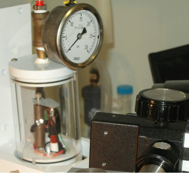
Figure 18. Pressure chamber used to test the effect of pressure on corona discharge.
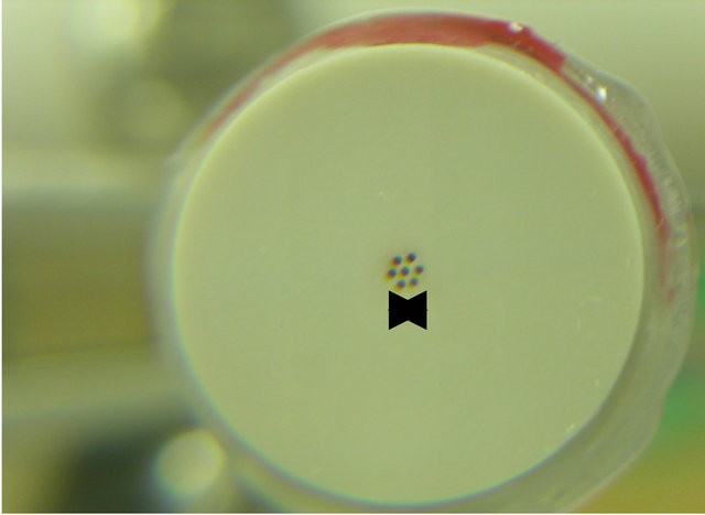
given a 1 mm tip size, the overall size for a 108 array seems prohibitive (100 m2). Figure 19 shows a linear array of four operating Taylor cone-jets, drawn from porous pen tips (costing $0.01 per tip) operating against a wire mesh counter electrode. They formed cone-jets and sprayed in synchrony with remarkable ease.
We also machined 2D arrays of pyramids in porous plastic and carbon as shown in Figure 20. The size of these arrays was smaller (0.3-mm pitch, 10 m2 minimum
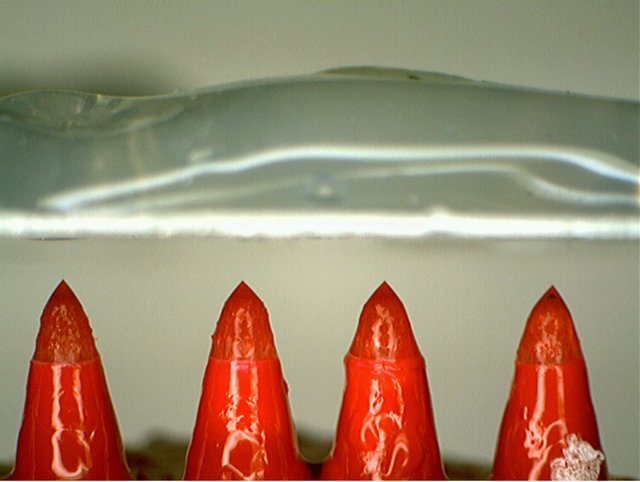
Figure 19. 1 × 4 array of Taylor cones emitting simultaneously.
Figure 20. An array of machined porous plastic pyramid tips for Taylor cone formation, and a porous carbon tip supporting a Taylor cone.
total) but still a bit prohibitive for scale-up to the required number. Porous carbon tips turned out to be the best material for this application. But even these arrays had very limited operational success due to water accumulation in other areas away from the tips. Porous surfaces would thus need to be sealed everywhere, except for the very tip.
2.6.3.2. Micromachined Silicon Spray Assemblies Recently, there has been substantial work and progress in the application of micro-machining for multiple Taylor cone spraying. Work in this area has been carried out for almost a decade at MIT, Yale, and EPL, directed towards the development of micro-thrusters for satellite positioning. Such thrusters have typically only a couple dozen capillaries spaced about 0.3 mm apart and have very limited spray capacity, but can in principle bescaled up without problem. A recent example of this can be seen in the remarkable work of Kproun [26], who describes a hexagonal array of etched silicon capillaries, formed by deep RIE (Reactive Ion Etching) with orifice diameter ranging from 24 to 32 µm. To increase the flow impedance of the capillaries, they are filled with 4.7-µm diameter silica spheres. A separate micro-machined silicon extraction plate, with holes corresponding to each nozzle, provides the required high extraction field.
Perhaps most relevant for silicon micromachining is the recent work by the Yale group of Deng et al. [36], which is more geared towards mono-disperse spraying for commercial applications such as pharmaceuticals or other high value materials. As in the work described above, there is a nozzle plate with micromachined capillaries and an extractor plate, both aligned and keyed-in together kinematically with etched V-grooves and alignment fibers. Both plates are made by standard micromachining techniques. The droplets sprayed from these arrays are remarkably uniform in size (within 10% uniformity over the full array, neglecting satellites) using ethanol as the spray medium. With the low conductivity fluids used, droplets were approximately 5 µm in diameter, but this is mostly a function of the fluid conductivity. Arrays with 331 jets and jet densities over 11,000/cm2 were fabricated (approximately 100 µm emitter spacing). Assuming this jet density, an approximately 1-m2 nozzle array would be needed for our application.
With some adaptation, such arrays should work well for salt nuclei formation from seawater. Silicon etching allows the formation of long capillaries with holes having very high aspect ratios as required. While the fabrication technology of these devices is not trivial, they are well within the capabilities of most well equipped micromachining laboratories. However the capillaries are brittle and fragile and the fabrication process is expensive. For this reason, we explored alternative scale-up methods using polymeric materials.
2.6.3.3. Electro-Spray from Superhydrophobic Dielectric Films Considerable effort was put into investigating a different technique which, while unproven, seemed to offer the promise of a cheaper, rugged and more flexible device. This method, an adaptation of a method first suggested by Lozano [37] envisions using a thin polyimide sheet with drilled holes rather than capillary tubes for the nozzle plate and mostly inexpensive polymeric materials for the rest of the assembly. It needs to be emphasized that the nano-dimension of droplets obtained from Taylor cones is not a function of the diameter of the cone support, and the very precise dimensioning allowed by micromachining is not a strict requirement.
Lozano et al. at MIT were the first to demonstrate the low power advantages of spraying from a hole in a low dielectric constant sheet [37]. The Lozano arrangement, in the absence of a conducting capillary, concentrates the field at the liquid tip and allows for lower operating voltages and power requirements. Fabrication of a hole is in principle substantially easier than the construction of a long thin-walled capillary. Bocanegra et al. [38] successfully extended this work to small arrays of holes with a matching extractor plate for low conductivity liquids. Again each liquid cone is drawn out by the electric field from an extractor plate aperture, and each jet formed passes though its extractor hole. It is again envisioned that the spacing between holes in the array would be on the order of 100 µm, and hence the active area of a sprayer accommodating 108 holes might be on the order of 1 m2.
Attractive as this solution might seem in principle, there are two major technical hurdles for large-scale implementation in its original form. This method requires deep drilling in the dielectric material to form a thin tubular conduit behind each aperture. This long capillary is necessary to provide the required flow impedance to isolate the interactions between various apertures. While drilling a hole is much easier than forming a free-standing capillary, deep drilling of small holes remains a delicate operation, particularly for a very large number of them.
Secondly, the seawater needs to be contained by surface tension at the exit rim of each individual hole in the dielectric plate. Again, this becomes a challenging task for a very large number of apertures. As with the operation of Rayleigh jets, failure of containment at one orifice is likely to progress to adjacent holes and result eventually in catastrophic breakdown.
To overcome the deep drilling problem it is possible to use a combination of a porous substrate, intimately attached to a polyimide aperture sheet containing the drilled holes. This is schematically illustrated in Figure 21.
The porous block provides the required flow impedance and aperture flow isolation. The thin aperture sheet, which has a thickness of 3 to 4 times the diameter of the hole, requires only holes of relatively low aspect ratio, which are much easier to fabricate. An aspect ratio of 3 - 4 is enough to provide most of the desired field augmenttation with a low dielectric material. The porous block also acts simultaneously as a final filter to keep the spray holes from clogging.
The holes in the polyimide array can be made using a variety of methods including laser drilling and lithography. The desired aspect ratio is somewhat high for wet etching but is readily achievable with dry etching. Such arrays can also be made by fast and inexpensive laser drilling systems. We were able to use a Samurai UV marking system from DPSS Lasers [39], capable of drilling up to 50,000 holes/s. Given this capacity the drilling of 108 holes would seem a manageable task, requiring a 20- µm diameter hole every 100 µm over an area of 1 m². While single 20-µm holes can be readily drilled, for extended arrays, focus and quality control require a precision mechanical stage area that is not presently integrated with the instrument.
A small array of such holes in a polyimide film is illustrated in Figure 22. The extractor plate requires a congruent array of holes on the order of 60 µm in diameter. These can be made with advanced printed circuit board techniques, but thermal expansion coefficients need to be matched to maintain registration.
The second, and more taxing, condition is that the water emerging from the holes pulled by the electric field must be firmly pinned to the rim of the orifice to produce the desired Taylor cone. If not pinned at the orifice the fluid will coalesce into an uncontrolled blob. To this end the top surface of the polyimide sheet needs to be made superhydrophobic. A superhydrophobic surface is generally defined in the literature as having a contact angle (CA) for water greater than 150˚. This prevents the emerging liquid from spilling and propagating on the exit surface.
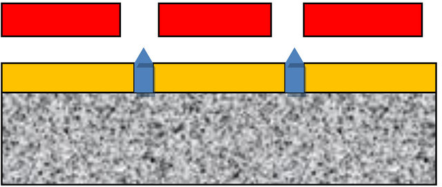
Figure 21. Proposed arrangement to replace a deep drilled block with a porous plastic substrate supporting a polyimide aperture plate, with extractor plate above. Relatively shallow holes are adequate, because the porous block provides adequate flow isolation.
The last few years have seen much progress in the production of superhydrophobic surfaces, and polyimide is well suited for this application [40]. In one of the ways to produce these surfaces, the smooth surface is first modified to obtain a micro-roughness on the order of 0.3 µm in an oxygen plasma-asher, and is then plasma coated with a few hundred angstroms of a fluorocarbon film. All of these are fairly routine processes for a semiconductor fab, and were executed at the Stanford Nanofabrication Facility.
Using this approach, Byun et al. [41] have demonstrated the successful formation of pinned Taylor cones from water emerging from a polytetrafluoroethylene (PTFE)- treated surface for a small number of apertures (<10). The surfaces showed little degradation over a two-month period. No details on the spray are available, and it is not known if corona discharge was observed. If proven robust enough, this method would seem in principle to provide a simple solution for mass fabrication.
In our own experiments, we were able to demonstrate the cone-jet pinning under some conditions. Figure 23 (left) shows a jet emerging from a 25-µm hole in an untreated PEEK (polyether ether ketone) capillary, using alcohol as the spray medium. In spite of the fact that the surface tension of alcohol is less than 1/3 that of water, which would significantly tend to enhance surface spreading, the cone is perfectly constrained to the central capil-
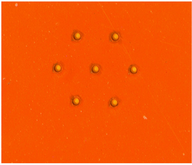
Figure 22. An array of UV-Laser-drilled holes, 25 µm in diameter, in a superhydrophobic Kapton film.
 (a)
(a) (b)
(b)
Figure 23. (a) Cone jet from a 25-µm PEEK capillary spraying alcohol, pinned at the hole periphery (illuminated by a green laser beam); (b) An emitter structure on treated superhydrophobic PEEK film.
lary in the PEEK tube. But water containing surfactant could not be sprayed successfully with this arrangement.
We constructed some deep drilled holes in PEEK to simulate the configuration of Bocanegra et al. [38]. Figure 23 (right) shows an array of seven deep-drilled (2.5- mm), close-packed holes, 250 µm in diameter, 375 µm apart drilled with an NC (numeric controlled) milling machine. The finished part was processed at the Stanford Nanofabrication Facility to make it superhydrophobic. An aluminum extractor electrode, with matching holes, separated by 250 µm was included.
Testing of the seven-hole array was not successful. These holes are big enough so that surfactant needs to be used to avoid corona discharge. Salt water would fill in between the extractor plate and exit holes, before cones could be made to spray. The surface of the PEEK film had a rough texture from the machining, and we believe that this together with surfactant use destroyed the desired pinning expected from superhydrophobic properties.
In spite of a substantial effort and the production of superhydrophobic surfaces of excellent quality for pure water (often in excess of 150˚ contact angle), in general none of these surfaces could reliably pin the liquid at the rim of the hole as desired if any surfactants were added to the water There is at least one reference in the literature [42] suggesting that certain classes of surfactant might not interfere, but this was not born out experimentally. A commercial superhydrophobic coating (Repellix™) [43] was also tried without success.
The holes were usually drilled after application of the superhydrophobic coating, which may have produced some slag or debris around the hole periphery, which might interfere with the operation of the coating. Coating after drilling was tried but this produced the same outcome. The optimal implementation, spraying in a 0.12 MPa atmosphere without surfactant, was not implemented because it became apparent over time that success with flat sheets would be a difficult proposition. The desired perfect cone operation with its associated preservation and maintenance of the required delicate surface properties appears to be a daunting undertaking, particularly in the taxing marine environment of sea-going ships.
2.6.3.4. Spraying from Shallow Photopolymer Capillaries As described above, Taylor cone spraying of seawater from drilled flat sheets is fraught with considerable experimental difficulties. In the flat sheet structure, there must be a perfect balance between the cone-jet flow, evaporation from the cone and the externally imposed liquid flow, or the hole may overflow and liquid will spread, as there is no alternate path for the liquid to follow. Failure of fluid retention at a single hole, even more so than in Rayleigh spraying, tends to propagate quickly and could result in catastrophic failure for the entire module subsection.
For all these reasons, we believe that a more promising approach is the fabrication of short aspect ratio capillaries in polymeric materials using a combination of photopolymers and polyimide. The suggested structure is illustrated in Figure 24. The capillary protrusions above the lower plate may be on the order of 60 µm, the outer nozzle diameter 40 µm, the inner diameter 20 µm, with the extractor plate of 50-µm holes placed 50 µm above the top of the nozzle protrusion.
Once again, by attaching a porous filter base plate as described above, the required length and flow impedance of the capillaries can be decreased, allowing for the use of short capillary structures. Air is envisioned to flow through the extraction holes, as will be described below.
Microscopic short aspect ratio capillaries may be fabricated by a number of methods, perhaps the easiest one being the use of photopolymers. The epoxy structures obtained from these are believed to be durable enough for the envisioned application.
High aspect ratio epoxy resist structures using Su-8 200 resist from MicroChem are illustrated in Figure 25. This is a near-UV epoxy resist, which becomes highly cross linked after exposure and baking, and is extremely durable. Here the resist structure is the end-product. The resist can be applied in coatings as thick as 200 µm in a single application.
Perhaps the premier industrial example of this fabrication method is the polymer inkjet head developed by Hewlett-Packard. HP’s scalable printing technology makes print heads with up to 1200 nozzles per inch, and modules are assembled into sections up to 30 inch wide for digital printing presses. In fact the HP thermal ink head fabrication, which includes a silicon resistor and multiple laminations requiring very careful alignment, is significantly more complex than what would be required for the
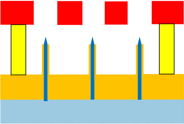
Figure 24. Cross-section of a spray device using short machined or molded micro-capillaries attached and supported by a filter/diffuser layer.
desired spray structures.
An example of thermal inkjet head fabrication of 2002 vintage is illustrated in Figure 26. The droplet jetting hole is on the order of 15 µm and the hole periodicity is on the order of 43 µm. The round posts, which are used as ink filters are typically 8 µm in diameter and have an aspect ratio of 3.5:1. For reference, the finest droplets used in ink jet printing are on the order of a picoliter (10−12 kg), which is more than seven orders of magnitude larger in volume than the desired droplets for MCB. These features are all produced by wet etching using photolithographic techniques and laminated with micron-scale precision.
All of this is to demonstrate that the use of silicon micromachining is not mandatory for short aspect ratio structures. In the structure of Figure 25, if there is a flow mismatch (e.g., the imposed liquid flow is slightly larger than the cone-jet flow) the excess fluid may drop down the capillary into the lower space without interference. The protrusion of the capillaries from the bottom plate provides a space that can serve as a drain for liquid ema-
Figure 25. Image of 10-µm features in 50-µm thick SU-8 coating (courtesy MicroChem).
Figure 26. Illustration of an ink jet nozzle device. Each nozzle consists of a silicon heater at the bottom, surrounded by a polymeric ink chamber to control the bubble size and topped by an orifice hole in polyimide. The pillars and cavities are used for filtering and controlling ink flow.
nating from overflowing, missing, or malfunctioning capillaries. The ability to use a less than perfect device provides an enormous advantage in manufacturing and during operation. Using as an example 4-inch wafer modules, a single module might yield a half million mechanical structures. While the fabrication of a perfect structure is not impossible with modern fab equipment, allowing for a few imperfections provides an enormous advantage in manufacturing yield and operation. Roughly some 200 wafer modules would be required to produce 108 capillaries for the target of 1017 nuclei/s.
It is likely that some salt buildup will occur over time around the capillaries, and perhaps in the extractor plate holes. Therefore, to remove long term salt build up, it is suggested that the spraying be periodically stopped, and the whole array be flooded with salt water to dissolve the salt deposits.
For robustness and low cost, the top extraction plate may be made by advanced printed circuit board techniques using some of the same processes employed in the hole array fabrication. As illustrated in Figure 24 posts attached to the top extractor separate the extractor and nozzle plate, which are clamped together since the space in between is pressurized at 0.12 MPa. Ideally, the separation between the extractor electrode and nozzle capillaries must be maintained completely uniform to achieve the desired spraying of all cones in synchrony at the same voltage. The applied pressure will, of course, cause some deformation of the extractor plate. The startup voltage for jetting from a Taylor cone is a logarithmic function of the ratio of the tip to plate separation versus the cone radius, and thus a 10% deviation in tip separation actually results in only a 2% - 3% variation in the startup spray conditions, which is probably acceptable.
2.6.4. Air Assist for Taylor Cone Jets and Power Considerations
Raising the air pressure to 0.12 MPa improves air breakdown and thereby eliminates corona discharge. There is however a large secondary advantage. Air flowing through the holes helps in the formation and guidance of the conejet and the formed droplets. In fact, with sufficient airflow, the flow by itself is capable of forming jets without electrical assist, a condition called flow focusing [44]. Even if the air pressure is too low to form jets as in flow focusing, the flow helps considerably in driving the spray through the orifice and keeping things clean.
Perhaps even more important from a practical point of view, the airflow helps in the dispersal and elimination of the space charge cloud which is formed and which gives rise to substantial problems, including wall deposition. To mitigate the space charge effects at least partially, alternate modules can be set up such that positive and negative polarity droplets are sprayed so that the net global space charge is close to zero. This will of course increase coagulation if complete drying before mixing does not take place.
As will be discussed in the next section, the power needed to create the air flow is larger than the electrical power needed to form the cone-jets.
Based on data from the experiments with Eppendorf capillaries, at a flow rate of 12 µL/hr (3.33 nL/sec) with 3 kV applied potential, drawing 1.33 µA, yielding salt particles of 46.6 nm equivalent sphere diameter, each jet gives approximately 109 droplets/s, thus requiring 108 jets. As each capillary uses approximately 4 mW of electrical power, the complete array would require a total of 400 kW of power. However, using the proposed microfabricated device, we may expect the electrical power to be reduced by a factor of 4 to 5, as the operating voltage can be reduced.
The total liquid flow is approximately 0.33 L/s. The total gas flow through all 108 holes at 0.02 MPa overpressure is 28 m3/s, and the required pneumatic power is then roughly 560 kW. The total required power is thus estimated to be on the order of 700 kW. This is an unacceptable high air flow rate. Dropping the overpressure by a factor 10 results in a more manageable flow of 8 m3/s, and requires only 18 kW of pneumatic power. The total amount of power may then be on the order of 150 kW. For the proposed design of Figure 24, surfactant then needs to be added to avoid corona at the lowered pressure. The air velocity in the gas orifices is still 45 m/s, probably adequate for its intended purpose The optimum pressure value is probably best determined experimentally, fitting the needs for rapid particle dispersion and avoidance of coalescence.
While this is a substantial amount of power, it would be readily available on commercial seafaring vessels or special sailing ships. For reference purposes, the power rating of diesel engines used on large container ships ranges from 30 to 80 MW. The electrical and pneumatic power required for a sprayer system is a small fraction of this. However, this amount of power is less than that required for complete evaporation of the water (750 kW), and thus evaporative cooling will still occur, but the amount of water sprayed is 100 times less than in Rayleigh spraying.
2.7. Taylor Cone Spraying from Suspended Droplets
Applying a large electric field to a suspended drop leads to a deformation along the field axis and eventually to instability as described by Taylor [24]. Cone-jets of opposite polarity then form at opposite ends of the deformed parent drop [16] and daughter droplets of opposite polarity are ejected. This is a field-induced instability, without loss of net charge of the parent drop, and which continues until the radius of the drop has fallen below the stability threshold, or the field is removed. There is very good reason to believe that these cone jets will produce daughter droplets similar in size to those emanating from capillaries and hence suitable for MCB if seawater is used.
In principle the array of micro-fabricated capillaries could be replaced by a moving array of large drops, which are ejecting small daughter droplets as long as they are in the applied field. 2D arrays of nearly identical drops can be formed by creating Rayleigh breakup of numerous parallel jets travelling between parallel electrodes to induce droplet fission. High speed air is used to suspend the drops. This would simplify the hardware very significantly, because the spraying of the parent drops is straight-forward. The required Taylor field is quite high, and must remain below the macroscopic air breakdown field (3 V/µm). Using surfactants, a target parent drop size might be 200 µm diameter, which would break down at 2.5 V/µm. It seems reasonable to assume that 108 moving drops can be continuously maintained in a flat 2 × 2 × 0.2-m flow-through box, those leaving the field in the box being discarded and replaced by new ones injected. The required electrical power consumption is quite high because the field extends over large spatial areas. The required driving voltage would be 500 kV, and assuming each Taylor cone carries roughly the same current as observed with capillaries (approx. 1 µA) this would require approximately 50 MW of electrical power. Both positive and negative nuclei are formed in this process, causing concern for coalescence. The hardware for this implementation looks quite simple, but the electrical requirements are taxing.
3. Conclusions
Of all the methods reviewed so far, by far the most promising results have been obtained with Taylor conejet spraying. By a fortuitous coincidence, the conductivity of seawater is such that it produces droplets in the right range for cloud nuclei when sprayed from these cone jets. Each Taylor cone produces on the order of 108 to 109 nuclei/s, and thus on the order of 108 Taylor cones would be needed to reach 1017 nuclei/s. The envisioned sprayers would have a size of roughly one square meter.
The fabrication of large arrays of Taylor cones, either by silicon micro-machining or with precision molded or plated structures seems feasible, although by no means trivial. No such large arrays have yet been constructed.
It is anticipated that handling of the space charge effects and the avoidance of coalescence are perhaps the largest unknowns. The development costs for such an array are estimated to be on the order of $4 - 5 million.
As a simpler alternative we are exploring the spraying of seawater at or near its critical point. In this regime, water has little or no surface tension and a gas-like viscosity and hence should disperse very much like a gas, in extremely small droplets. Preliminary results are encouraging, with the mean particle size in the desired range, but with broader distribution widths. The results of this investigation will be reported at a later date.
4. Acknowledgements
Funding for elements of this research was provided by the Fund for Innovative Climate and Energy Research (FICER) at the University of Calgary. The authors thank David Keith and Ken Caldera, the Fund administrators, for their support and encouragement of this work. We are also indebted to Holly Roberts at the University of Calgary for her administrative expertise.
Part of this work was performed at the Stanford Nanofabrication Facility, supported by National Science Foundation Grant ECS-9731293. We are particularly indebted to Jim Kruger and Paul Rissman of the Stanford Nanofabrication Facility for their contributions and advice.
Numerous former friends and colleagues contributed and supported this work and were part of the team at some time: Brian Leslie, Ralph Wolf, Dave Donald, John Myer, Frank Koenig, John Vaught, Gary Gordon and Larry Hubby.
Jim Lovelock encouraged us throughout this project, and clarified important issues in surface tension. John Latham was perhaps our most ardent fan throughout this work.
We are indebted to numerous people who lend us their support freely:
• The personnel of Metara, Inc. for numerous instances of help and equipment loans;
• Thomas Mee from Mee Industries for the loan of the Malvern Spraytech Instrument, and discussions on spraying in general;
• Phil Mauger and Alex Shimkunas from Nanostructures for supplying us with free sample wafers, and the fabrication of plated nozzles;
• Alex Laymon and Randy Kimball from DPSS Lasers, Inc. for their expert fabrication of laser drilled holes;
• Walter Bachman of Bachmann Instruments for readily providing his unequalled expertise in SEM imaging, and for equipment loans;
• Thomas Leisner and his team at KIT for their info on droplet Coulomb fission;
• Dan Hirleman from Purdue University for the loan of calibration targets, and John Abraham, also from Purdue, for guidance in high pressure spraying;
• MBARI for facilitating measurements on very high pressure jets;
• Nelson Machining of its prompt execution of challenging machining jobs;
• Hamilton Precision Metals for free titanium foil samples.
REFERENCES
- J. Latham, “Control of Global Warming?” Nature, Vol. 347, No. 6291, 1990, pp. 339-340. doi:10.1038/347339b0
- J. Latham, P. Rasch, C.-C. Chen, L. Kettles, A. Gadian, A. Gettlelman, H. Morrison, K. Bower and T. Choularton, “Global Temperature Stabilization via Controlled Albedo Enhancement of Low-level Maritime Clouds,” Philosophical Transactions of the Royal Society A, Vol. 366, No. 1882, 2008, pp. 3969-3987. doi:10.1098/rsta.2008.0137
- S. Salter, G. Sortino and J. Latham, “Sea-Going Hardware for the Cloud-Albedo Method of Reversing Global Warming,” Philosophical Transactions of the Royal Society A, Vol. 366, No. 1882, 2008, pp. 3843-3862. doi:10.1098/rsta.2008.0136
- J. Latham, K. Bower, T. Choularton, H. Coe, P. Connolly, G. Cooper, T. Craft, J. Foster, A. Gadian, L. Galbraith, H. Iacovides, D. Johnston, B. Launder, B. Leslie, J. Meyer, A. Neukermans, B. Ormond, B. Parkes, P. Rasch, J. Rush, S. Salter, T. Stevenson, H. Wang, Q. Wang and R. Wood, “Marine Cloud Brightening,” Philosophical Transactions of the Royal Society A, Vol. 370, No. 1974, 2012, pp. 4217-4262. doi:10.1098/rsta.2012.0086
- T. Mee, “Mee Industries,” Private Communication, 2009.
- M. Chaker, C. Meher-Homji and T. Mee, “Inlet Fogging of Gas Turbine Engines: Experimental and Analytical Investigations on Impact Pin Fog Nozzle Behavior,” Journal of Engineering for Gas Turbines and Power, Vol. 128, No. 4, 2006, pp. 826-839. doi:10.1115/1.1808429
- J. L. York, H. E. Stubbs and M. R. Tek, “The Mechanism of Disintegration of Liquid Sheets,” Transactions on ASME, Vol. 75, No. 7, 1953, pp. 1279-1286.
- R. P. Fraser, P. Eisenklam, N. Dombrowski and D. Hasson, “Drop Formation from Rapidly Moving Liquid Sheets,” AIChE Journal, Vol. 8, No. 5, 1962, pp. 672-680. doi:10.1002/aic.690080522
- L. Rayleigh, “On the Instability of Jets,” Proceedings of the London Mathematical Society, Vol. 10, No. 1, 1878, pp. 4-13. doi:10.1112/plms/s1-10.1.4
- S. D. Sovani, P. Sojka and A. Lefebvre, “Effervescent Atomization,” Progress in Energy and Combustion Science, Vol. 27, No. 4, 2001, pp. 483-521. doi:10.1016/S0360-1285(00)00029-0
- B. Leslie, A. Neukermans, T. Simon and J. Foster, “Enhanced Brightness X-Ray Source,” Journal of Vacuum Science & Technology B, Vol. 1, No. 4, 1983, pp. 1251- 1256. doi:10.1116/1.582763
- L. Rayleigh, “On the Equilibrium of Liquid Conducting Masses Charged with Electricity,” Philosophical Magazine, Vol. 14, No. 87, 1882, pp. 184-186. doi:10.1080/14786448208628425
- J. A. Crabb and J. Latham, “Multiplication of Condensation Nuclei by Bursting Droplets,” Journal de Recherches Atmospheriques, Vol. 6, 1972, pp. 79-87. doi:10.1038/421128a
- D. Duft, T. Achtzehn, R. Müller, B. Huber and T. Leisner, “Coulomb Fission: Rayleigh Jets from Levitated Droplets,” Nature, Vol. 421, No. 6919, 2003, p. 128. doi:10.1038/421128a
- E. Giglio, B. Gervais, J. Rangama, B. Manil, B. Huber, D. Duft, R. Muller, T. Leisner and C. Guet, “Shape Deformations of Surface Charged Microdroplets,” Physical Review E, Vol. 77, No. 3, 2008, Article ID: 036319.
- R. L. Grimm and J. L. Beauchamp, “Dynamics of Fluid Induced Droplet Ionization,” The Journal of Physical Chemistry B, Vol. 109, No. 16, 2005, pp. 8244-8250. doi:10.1021/jp0450540
- T. Leisner, Karlsruhe Institute of Technology, Private Communication, 2010.
- J. Vaught, Private Communication, 2009.
- J. Huang, “The Breakup of Axi-symmetric Liquid Sheets,” The Journal of Fluid Mechanics, Vol. 43, No. 2, 1970, pp. 305-319. doi:10.1017/S0022112070002392
- J. Abrahams, Purdue University, Private Communication, 2009.
- Monterey Bay Aquarium Research Institute (MBARI), Moss Landing, California, USA.
- A. Neukermans, “Optical Sizing of Monodisperse Toner,” Xerox Corporation Technical Report 22302, 1973.
- J. Zeleny, “Instability of Electrified Liquid Surfaces,” Physical Review, Vol. 10, No. 1, 1917, pp. 1-6. doi:10.1103/PhysRev.10.1
- G. Taylor, “Disintegration of Water Drops in an Electric Field,” Proceedings of the Royal Society A, Vol. 280, No. 1382, 1964, pp. 383-397. doi:10.1098/rspa.1964.0151
- M. Martínez-Sánchez, J. Fernandez de la Mora, V. Hruby, M. Gamero-Castano and K. Khayms, “Research on Colloid Thrusters,” 26th International Electric Propulsion Conference, Kitakyushu, 17-21 October 1999.
- R. Kproun, “Micromachined Electrospray Thrusters for Spacecraft Propulsion,” Thesis, Ecole Polytechnique Federale de Lausanne, Lausanne, 2009.
- J. F. De la Mora, “The Fluid Dynamics of Taylor Cones,” Annual Review of Fluid Mechanics, Vol. 39, No. 1, 2007, pp. 217-243. doi:10.1146/annurev.fluid.39.050905.110159
- A. M. Gañán-Calvo and J. M. Montanero, “Revision of Capillary Cone-Jet Physics: Electrospray and Flow Focusing,” Physical Review E, Vol. 79, No. 6, 2009, pp. 066305 and 069905.
- J. M. Crowley, “Role of Joule Heating in the Electrostatic Spraying of Liquids,” Journal of Applied Physics, Vol. 48, No. 1, 1977, pp. 145-147. doi:10.1063/1.323299
- O. Lastow and W. Balachandran, “Novel Low Voltage EHD Spray Nozzle for Atomization of Water in the Cone Jet Mode,” Journal of Electrostatics, Vol. 65, No. 8, 2007, pp. 490-499. doi:10.1016/j.elstat.2006.11.004
- J. López-Herrera, A. Barrero, A. Boucard, I. Loscertales and M. Márquez, “An Experimental Study of the Electrospraying of Water in Air at Atmospheric Pressure,” Journal of the American Society for Mass Spectrometry, Vol. 15, No. 2, 2004, pp. 253-259. doi:10.1016/j.jasms.2003.10.018
- M. Cloupeau, “Recipes for Use of EHD Spraying in Cone Jet Mode and Notes on Corona Discharge Effects,” Journal of Aerosol Science, Vol. 25, No. 6, 1994, pp. 1143- 1157. doi:10.1016/0021-8502(94)90206-2
- J.-P. Borra, P. Ehouarn and D. Boulaud, “ElectrohydroDynamic Atomization of Water Stabilised by Glow Discharge,” Journal of Aerosol Science, Vol. 35, No. 11, 2004, pp. 1313-1332. doi:10.1016/j.jaerosci.2004.05.011
- D. Smith, “The Electrohydrodynamic Atomization of Liquids,” IEEE Transactions on Industry Applications, Vol. IA-22, No. 3, 1986, pp. 527-535. doi:10.1109/TIA.1986.4504754
- J. Rousse, “Emission Par Effect Couronne aux Hautes Temperatures et Pressions,” Doctoral Thesis, Universite de Paris, Paris, 1947.
- W. Deng, C. M. Waits, B. Morgan and A. Gomez, “Compact Multiplexing of Monodisperse Electrosprays,” Journal of Aerosol Science, Vol. 40, No. 10, 2009, pp. 907-918. doi:10.1016/j.jaerosci.2009.07.002
- P. Lozano, M. Martínez-Sánchez and J. M. Lopez-Urdiales, “Electrospray Emission from Non-Wetting Flat Dielectric Surfaces,” Journal of Colloid and Interface Science, Vol. 276, No. 2, 2004, pp. 392-399. doi:10.1016/j.jcis.2004.04.017
- R. Bocanegra, D. Galán, M. Márquez, I. G. Loscertales and A. Barrero, “Multiple Electrosprays Emitted from an Array of Holes,” Journal of Aerosol Science, Vol. 36, No. 12, 2005, pp. 1387-1399. doi:10.1016/j.jaerosci.2005.04.003
- DPSS Lasers Inc., Santa Clara, California, USA.
- M. I. Newton, P. Roach and N. J. Shirtcliffe, “Progress in Superhydrophobic Surface Development,” Soft Matter, Vol. 4, No. 2, 2007, pp. 224-240.
- D. Byun, Y. Lee, S. B. Q. Tran, V. D. Nugyen, S. Lee, S. Kim, N. Inamdar, B. Park and H. Bau, “Electrospray on Super Hydrophobic Nozzles Treated with Argon and Oxygen Plasma,” Applied Physics Letters, Vol. 92, No. 9, 2008, Article ID: 093507. doi:10.1063/1.2840725
- F.-M. Sheng, Y.-J. Sheng, H. Chen and H.-K. Tsao, “From Superhydrophobic to Superhydrophilic Surfaces Tuned by Surfactant Solutions,” Applied Physics Letters, Vol. 91, No. 9, 2007, Article ID: 094108. doi:10.1063/1.2779092
- RepellixÔ: Integrated Surface Technologies Inc., Menlo Park, California, USA.
- A. M. Gañán-Calvo, “Enhanced Liquid Atomization: From Flow-Focussing to Flow Blurring,” Applied Physics Letters, Vol. 86, No. 21, 2005, Article ID: 214101. doi:10.1063/1.1931057