Journal of Minerals and Materials Characterization and Engineering
Vol. 1 No. 6 (2013) , Article ID: 40047 , 7 pages DOI:10.4236/jmmce.2013.16051
Theoretical and Experimental Analysis of Deep Drawing Cylindrical Cup
1Department of Material Science, Saveh Branch, Islamic Azad University, Saveh, Iran
2Technical and Professional University, Imam Mohammad Bagher Technical College, Sari, Iran
Email: najarab@yahoo.com, javadimanesh@gmail.com
Copyright © 2013 Najmeddin Arab, Abotaleb Javadimanesh. This is an open access article distributed under the Creative Commons Attribution License, which permits unrestricted use, distribution, and reproduction in any medium, provided the original work is properly cited.
Received August 21, 2013; revised September 22, 2013; accepted October 15, 2013
Keywords: Deep Drawing Cylindrical Cup; Sheet Metal Forming; Analytical Analysis
ABSTRACT
There are mainly two methods of deep drawing analysis: experimental and analytical/numerical. Experimental analysis can be useful in analyzing the process to determine the process parameters that produce a defect free product, and the analytical/numerical modeling can be used to model and analyze the process through all stages of deformation. This approach is less time consuming and more economical. Sheet metal forming often includes biaxial in-plane deformation with non-proportional strain paths. In deep drawing of cylindrical cup, the deformation in the flange is dominated by pure shear deformation, while it changes to plane strain when the material is drawn into the die. This paper deals with the analysis of deep drawing of circular blanks into axi-symmetric cylindrical cup using numerical modeling. The blank drawability has been related both theoretically and experimentally with the initial diameter of the blank and deep drawing parameters. The strains in the radial and circumferential directions have been measured. A correlation on the flange thickness variation by taking into account the work hardening with the analytical and experimental values also has been searched.
1. Introduction
Production of high quality products in a short time and at low cost is an ultimate goal in manufacturing. To reach this goal, continuous progress is made at the design and at the floor shop levels of forming process [1]. The stages of research and development in CAD/CAM/CAE in relation with the analysis and design of forming parts can be observed from several papers published in proceedings of international meetings [2,3].
To avoid trial and error tryout procedures, the sheet metal forming simulation is increasingly being used in the stamping industry to evaluate the deformation paths and the forming defects such as fracture and wrinkling. Many research groups are still developing and improving finite element codes for the analysis when an initial design of the blank and the tools is done and when the forming conditions are defined. Several analysis tools are described in the proceedings [2,3].
They are based on membrane, shell or even solid elements, considering static or dynamic, implicit or explicit approaches. These analysis tools can be very precise if used by well-trained engineers, but they are time consuming and need expensive computer resources. Computer simulation can also be very attractive and helpful for the process and tooling engineers to define the initial blank (thickness, contour and surface), some process parameters (boundary conditions, holding forces, lubrication conditions, drawn types and positions, etc.) and the material properties (yield stress, hardening, anisotropy, etc.). This has been recognized by some industrial and academic research and development groups. As a result, numbers of methods have been developed in the last decade. They are mainly based on the fact that the shape of the desired part is known. A comparison is then made with the initial flat blank to estimate the deformation of the final product taking into account simple constitutive equations and assumptions regarding the tool actions. These simplified procedures have been called different names: “geometrical mapping method” [4], “single and multi-stage forming formulations” [5], “one step solution” [6], “ideal forming theory” [7], “inverse approach” (IA) [8-12] and “simplified approach” [13]. The inverse approach is based on a discretization of the final workpiece by simple triangular flat facet shell elements. For a large number of industrial applications, the membrane effects are dominant, but it has been necessary to consider bending effects using a simple discrete Kirchhoff shell element [14-16]. Assumptions were made regarding the action of the tools (punch and die) at the end of the forming process. Logarithmic strains and total deformation theory of plasticity were considered. The equilibrium of the workpiece leads to a set of nonlinear equations. These nonlinear equations can be solved by different techniques such as the Newton-Raphson static implicit approach, the dynamic relaxation method or the dynamic explicit algorithm [17-21]. The convergence difficulties can be encountered for practical situations involving deep drawing workpieces (with almost vertical walls) and a low plastic hardening law. A simplified scheme in order to estimate the trimming part of the workpiece for a given blank shape, flat or curved has been developed. The inverse approach has been continuously evaluated by comparing the numerical results with experimental and other numerical results obtained by incremental approaches. The procedure has been found very efficient and quite precise at the preliminary tool design stage [22,23]. Based on the idea of the simplified inverse approach, two industrial codes have been developed [24-26]. The codes are routinely used at the preliminary forming design stage of car panels and thin walled structural members. Some backwards simulation codes have been developed and used in the industry [27- 29].
In this paper, in order to increase the efficiency and accuracy of the modeling procedure, the yielding criteria and radial and circumference strains among with strain hardening and thickness variations during the forming process have been employed. Also experimental results are present to evaluate the theoretical method.
2. General Analysis Methods
2.1. The Different Deformation Modes
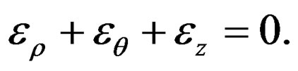
Figure 1 shows different deformation modes which can occurs in a cup drawing. By convention, any type of deformation in a sheet can be represented by a point in the ερ vs εθ diagram below, where ερ is the principal strain in the plane of the sheet and εθ is the strain perpendicular to ερ. The thickness strain εz is obtained from the law of conservation of volume:
This diagram show the different types of deformation possible during drawing. The deformation mode is visually represented in the chart by the deformation of the
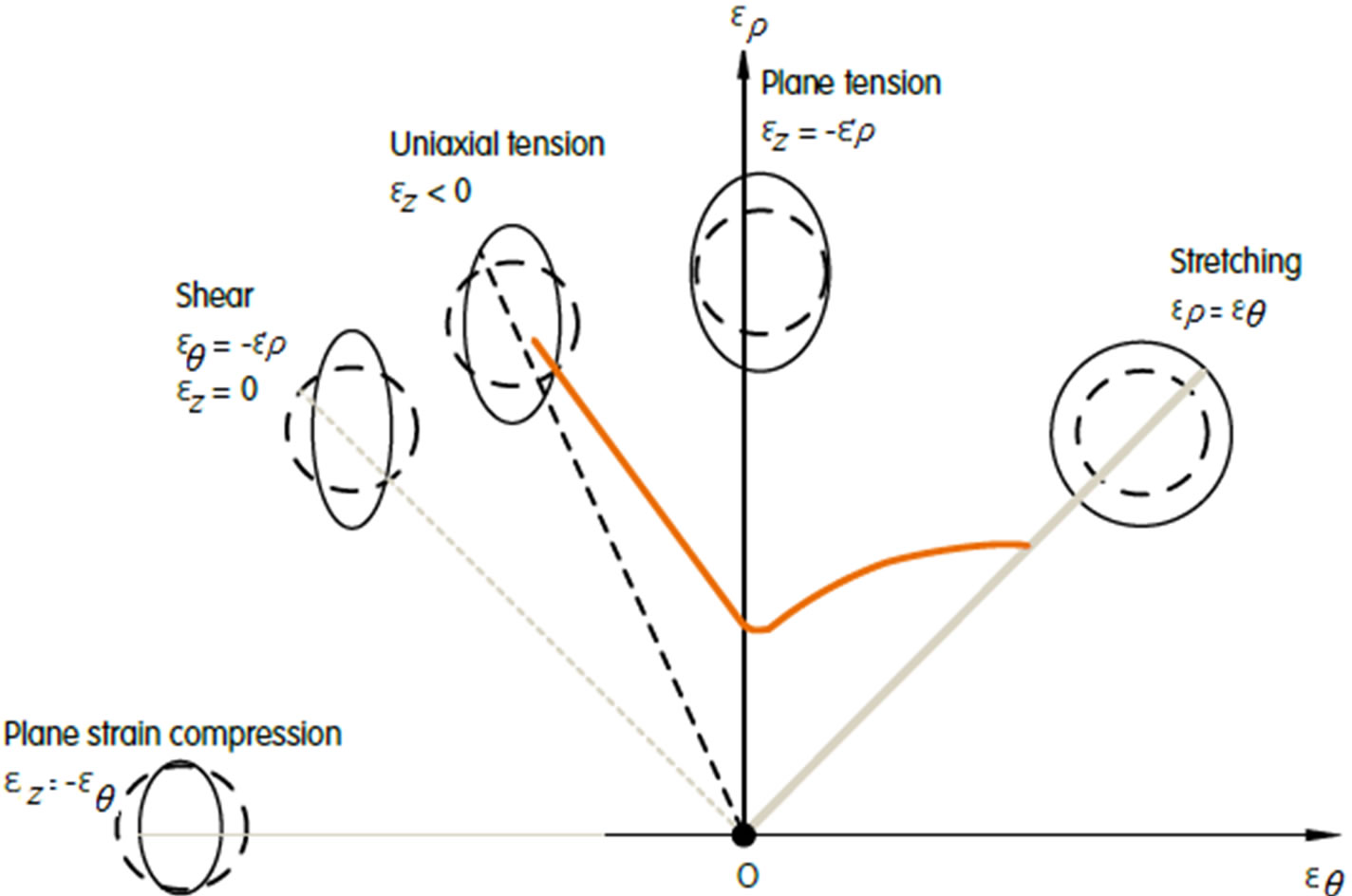
Figure 1. Strain diagram for steel forming showing a typical forming limit curve for steel blanks [30].
circle. In reality, the magnitude and mode of deformation of a component are each measured by optical measurement of a full pattern of circles or dots printed on a blank before deformation. Characteristic cases or deformation modes are:
• Stretching, or biaxial tension: this is accompanied by thinning and typically occurs in spherical shapes such as at the punch nose. The magnitude of deformation is largely defined by the shape and the restraining force on the flange, exerted by the blankholder.
• Plane strain tension: generally occurs in the vertical walls of the part, due to the tensile stress caused by retention under the blankholder, or just before the end of forming when sliding in the tool is restricted.
• Uniaxial tension: this is the situation encountered in a tensile test on a specimen, and it occurs in transition regions between zones of plane strain tension and plane strain compression.
• Shear deformation: represents the ideal forming mode; here, all tensile strains are being compensated by compressive strains, so that the thickness remains constant. This type of deformation can occur beneath the blankholder if the flow is uniform (axisymmetric drawing).
• Drawing: involves thickening due to a reduction in width (circumference). It is mostly unavoidable during deep drawing but can be controlled beneath the blankholder. However, its occurrence in unsupported areas will lead to wrinkling or folding [30].
2.2. Sheet Metal Forming at Axi-Symmetric Condition
The basic analytical theory used in the solution of the problem of deep-drawing a cylindrical cup is based mainly on the researches in references [31-40]. The analytical model is established on the following assumptions: elastic strains are neglected, since they are small compared with plastic strains, isotropic material, Von Mises material with non-linear strain-hardening is used, radial, circumferential, and thickness directions are considered principal directions, bending/unbending effects are neglected since their effect is negligible for a die profile radius to sheet thickness, shear stress is neglected across the thickness, and a straight cup wall is assumed. The principal directions in the problem of deep-drawing a cylindrical cup are the radial, circumferential and thickness directions with ρ, θ and z designations respectively. The governing plasticity equations of the analytical model are as follows: Effective Stress: For a material free from Bauschinger effects, Von Mises or effective stress is defined as follows [41,42]:
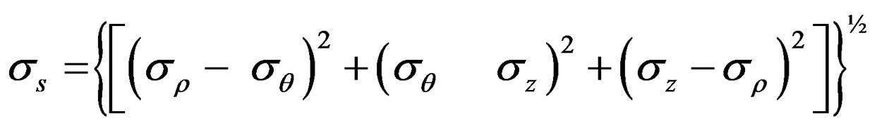 (1)
(1)
Plastic Strains for the three principal directions; circumferential, thickness, and radial directions can be expressed as:
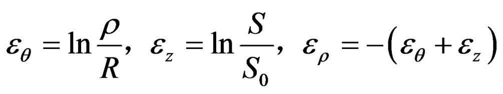 (2)
(2)
S0 is primary thickness of blank and R is primary blank diameter. The effective incremental strain can be stated as:
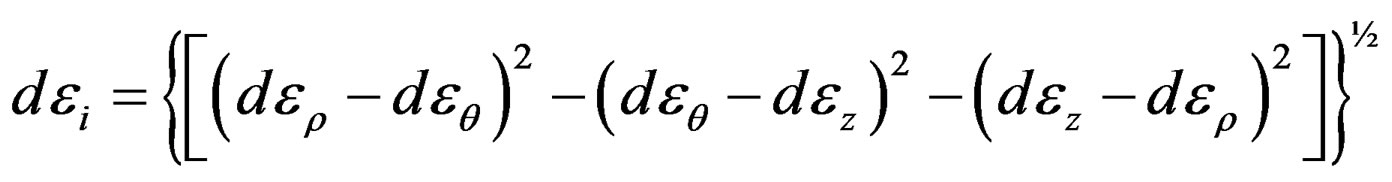
(3)
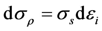
Stress-Strain Relationship: Based on Levy-Lode stress-strain relationship:
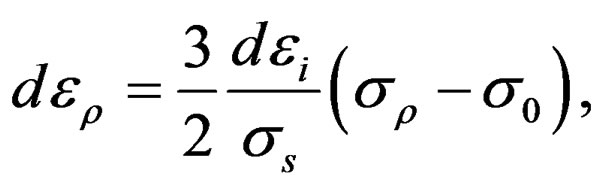 (4)
(4)
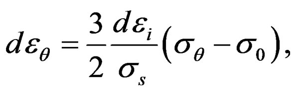 (5)
(5)
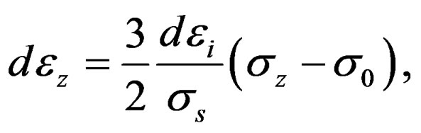 (6)
(6)
Flow Equation: The flow equation that describes the strain hardening of the material is the Ludwik-Hollomon power law which is given by [41,42]:
 (7)
(7)
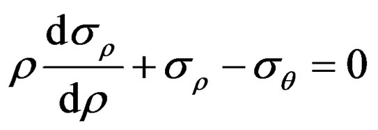
K and n are work hardening parameters depending on mechanical properties of material. The equilibrium equation for axi-symmetrically condition with variable thickness is:
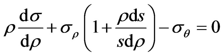 (8)
(8)
The major strains in circular and thickness directions thickness are:
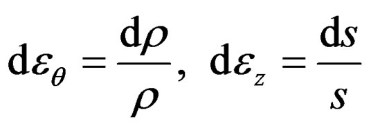 (9)
(9)
Substituting equation (9) in (8) and consideration equation (6):
 (10)
(10)
Solving this equation requires simplifications. Nazaryan [43] represent following equation:
 (11)
(11)
By assumption  and use of yield criterion
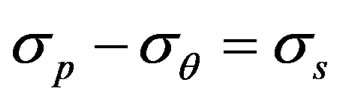 :
:
 (12)
(12)
which show equilibrium equation usually applied in researches without considering work hardening effect and thickness changes.
2.3. Analysis of Thin Ring Plates Deformation
Let’s consider thin ring plate having the sizes R0, S0 before drawing and r and s after drawing. Some of researchers represent the following equations to evaluate thin ring plate behavior during deep drawing process by taking into account work hardening and thickness changes and strains during deep drawing of cylindrical cups [44-47].
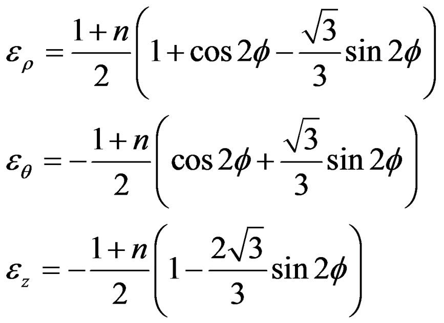 (13)
(13)
which φ is angle between rolling and drawing directions.
3. Experimental Section
The sheet metal used in this research was 2 mm thick with 148.5 mm diameter carbon steel sheet according to German Standard DIN-EN10130-FePO4-(St14). Chemical composition and mechanical properties of the material are show in tables 1 and 2.
The die was made from CK 45 medium carbon steel which the surface of punch and matrix was nitride hardening. Also the polyethylene papers (nylon) used as lubricant. The primary sheet size was 148.5 cm diameter that was demarcation the rolling direction. After drawing, the stains were calculated in rolling direction. The drawing process is shown in figure 2. The 50 tons hydraulic press was used to drawn the cups.
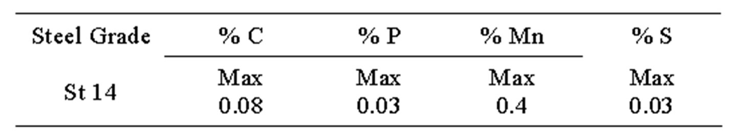
Table 1. Chemical composition of steel sheets.
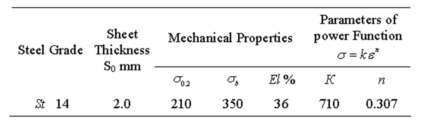
Table 2. Mechanical properties of steel sheets.
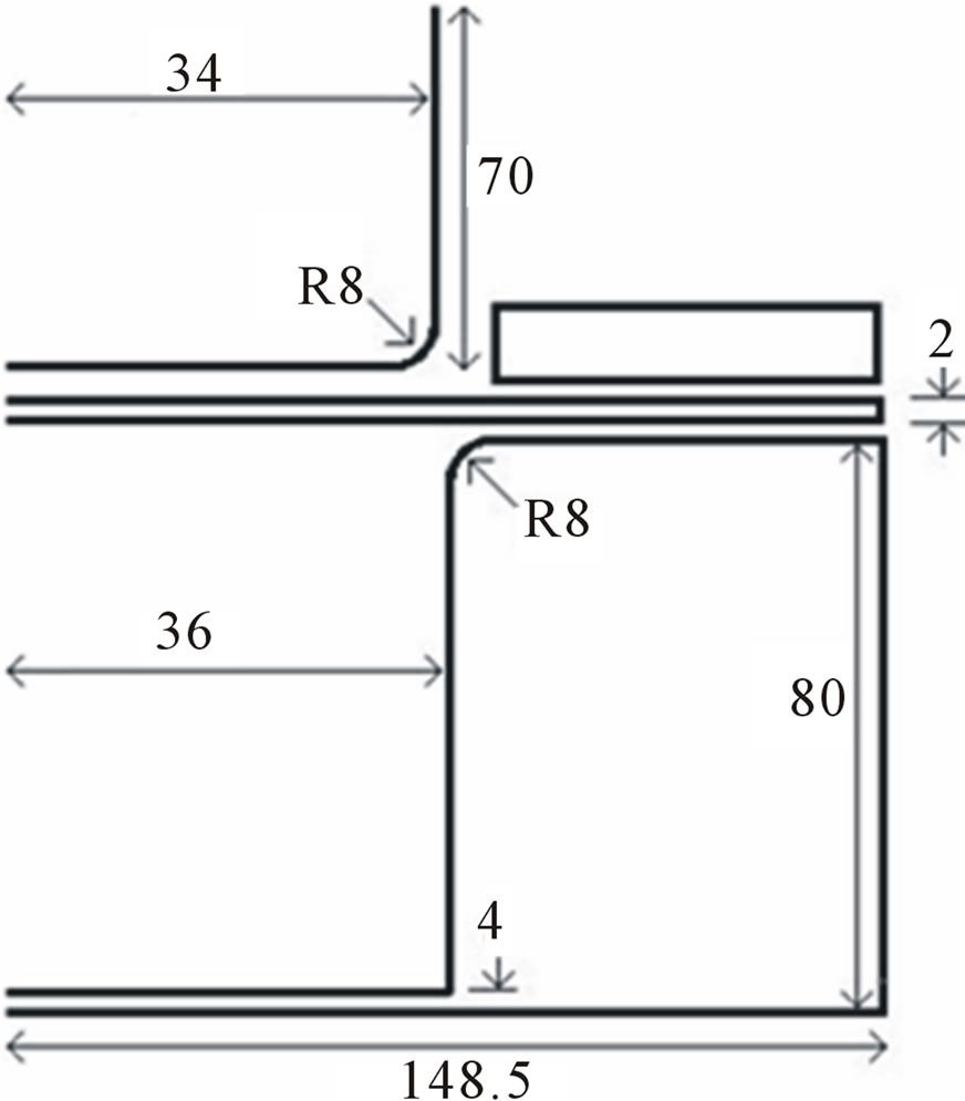
Figure 2. Schematic for cylindrical cup drawing process.
After the drawing process, the drawn parts were cut in rolling direction and the thickness was measured according to figure 3.
4. Results and Discussion
4.1. Analytical Modeling
Taking into account equations (3) and (13) and using computer MATLAB software to draw these equations, the relationship between the major strains in radial, circumference and thickness directions and equivalent strain can be obtained while the effect of work hardening has been considered as show in figure 4.
Using figure 4, the major strains in radial, circumference and thickness directions and equivalent strain can be measure after deep drawing process.
4.2. Experimental Results
The thickness measuring results from 9 positions in 24 drawn parts are presented in table 3. Also, Figure 5 show maximum thinning and thickness positions in drawn cups. According to the results of this research, for a blank with 2 mm thickness, the maximum thinning in drawn cups, occur in position 6 and it is next to 18% of blank thickness. Also the maximum thickening occur in
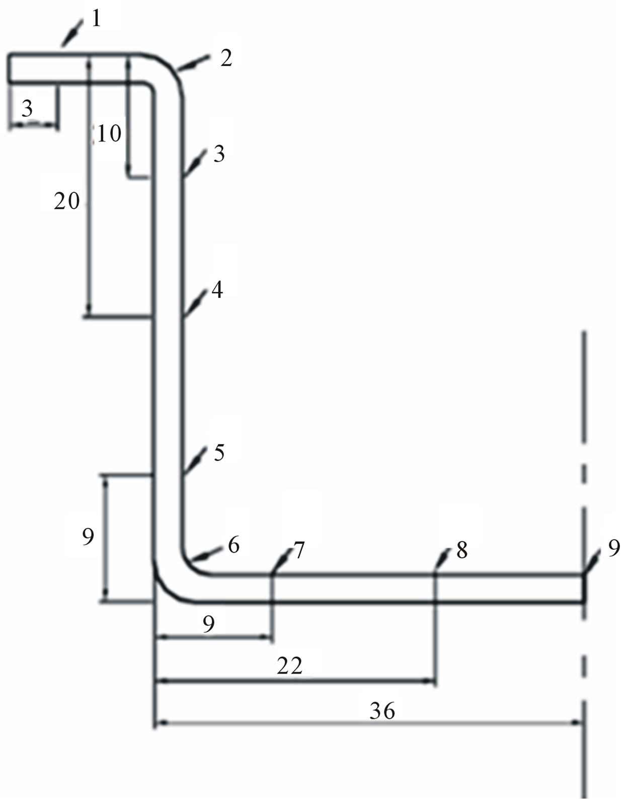
Figure 3. Measuring positions after cutting the drawing cups.
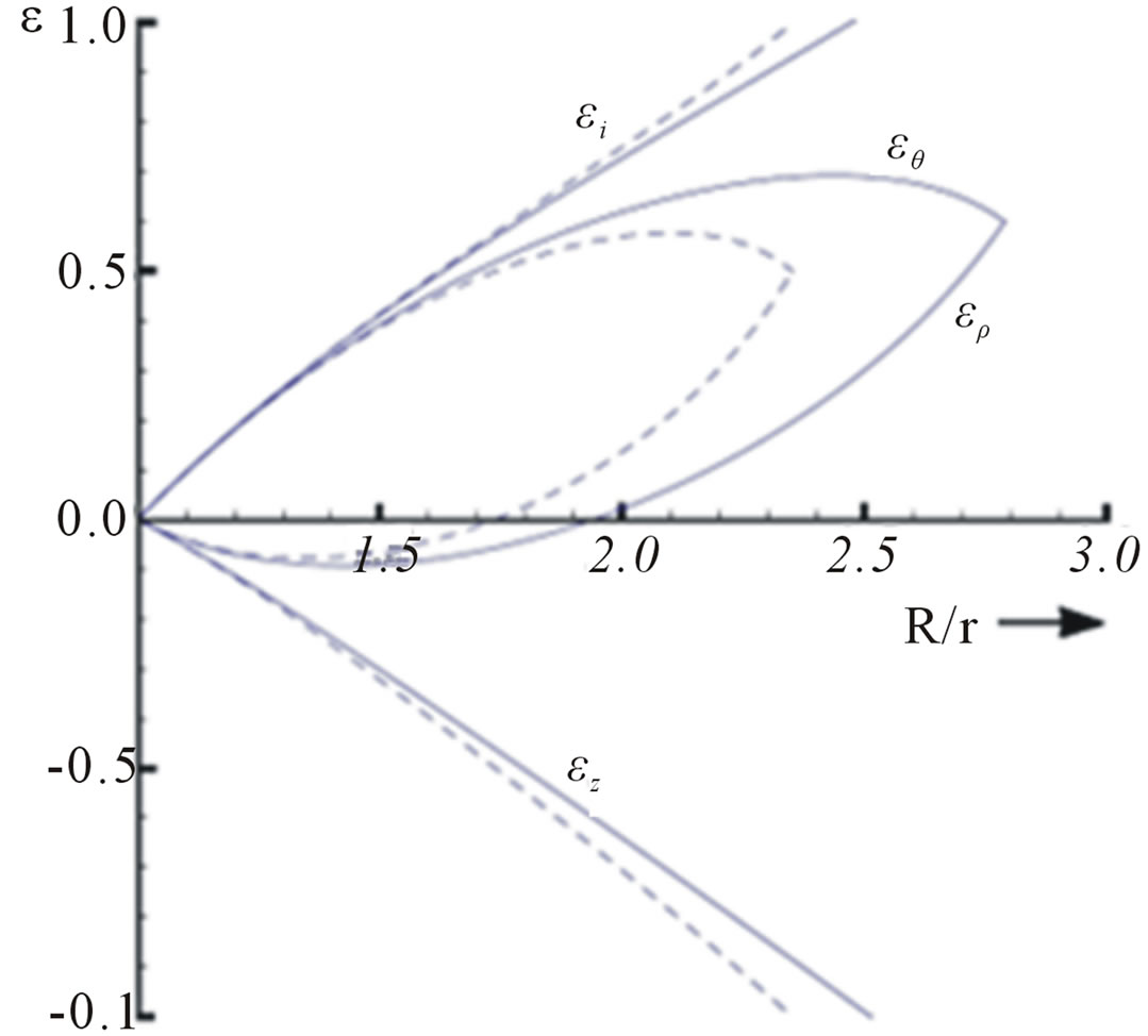
Figure 4. Distribution of non-dimensional equivalent and major strains for ring plates (r is punch diameter).
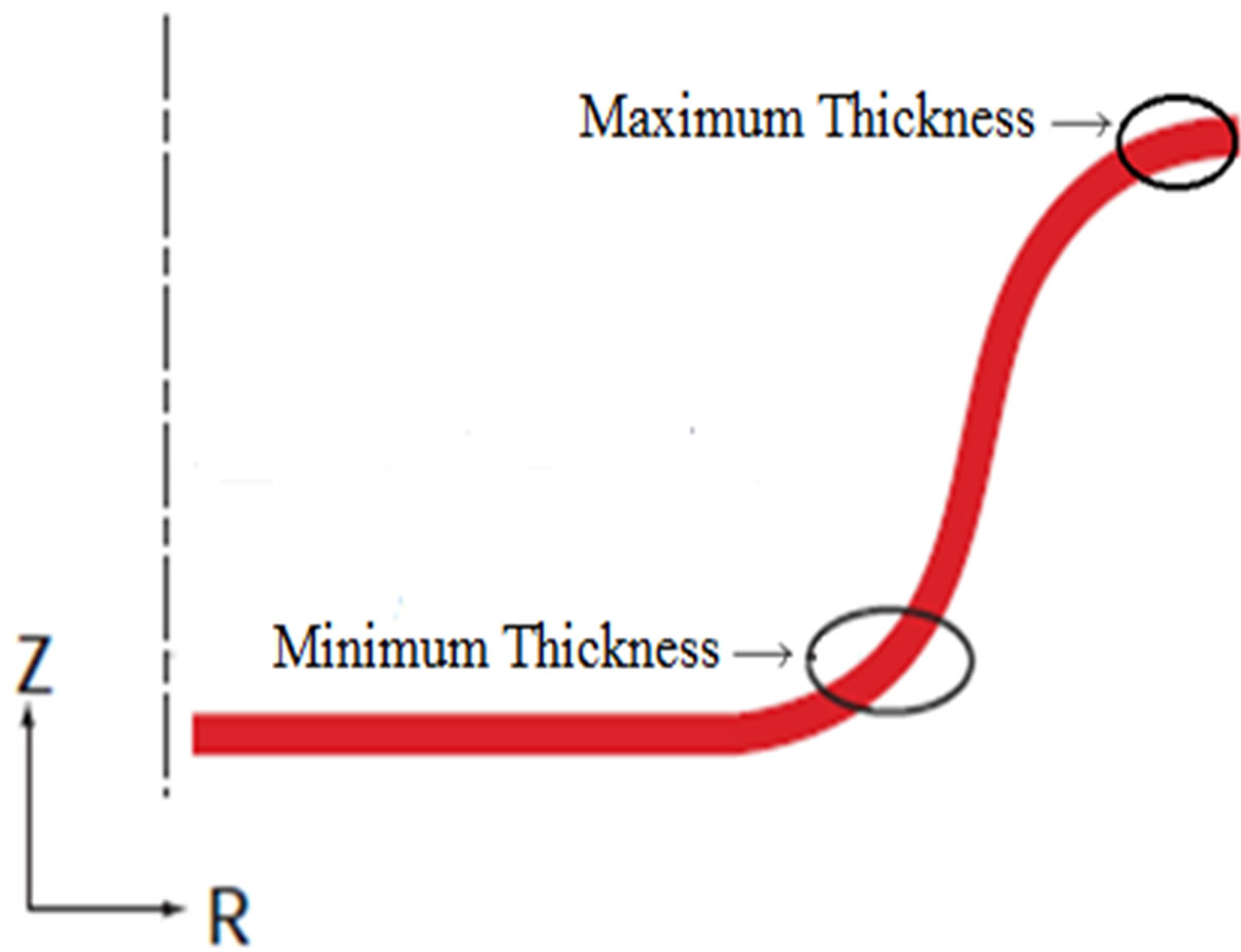
Figure 5. Maximum and minimum thickness positions.
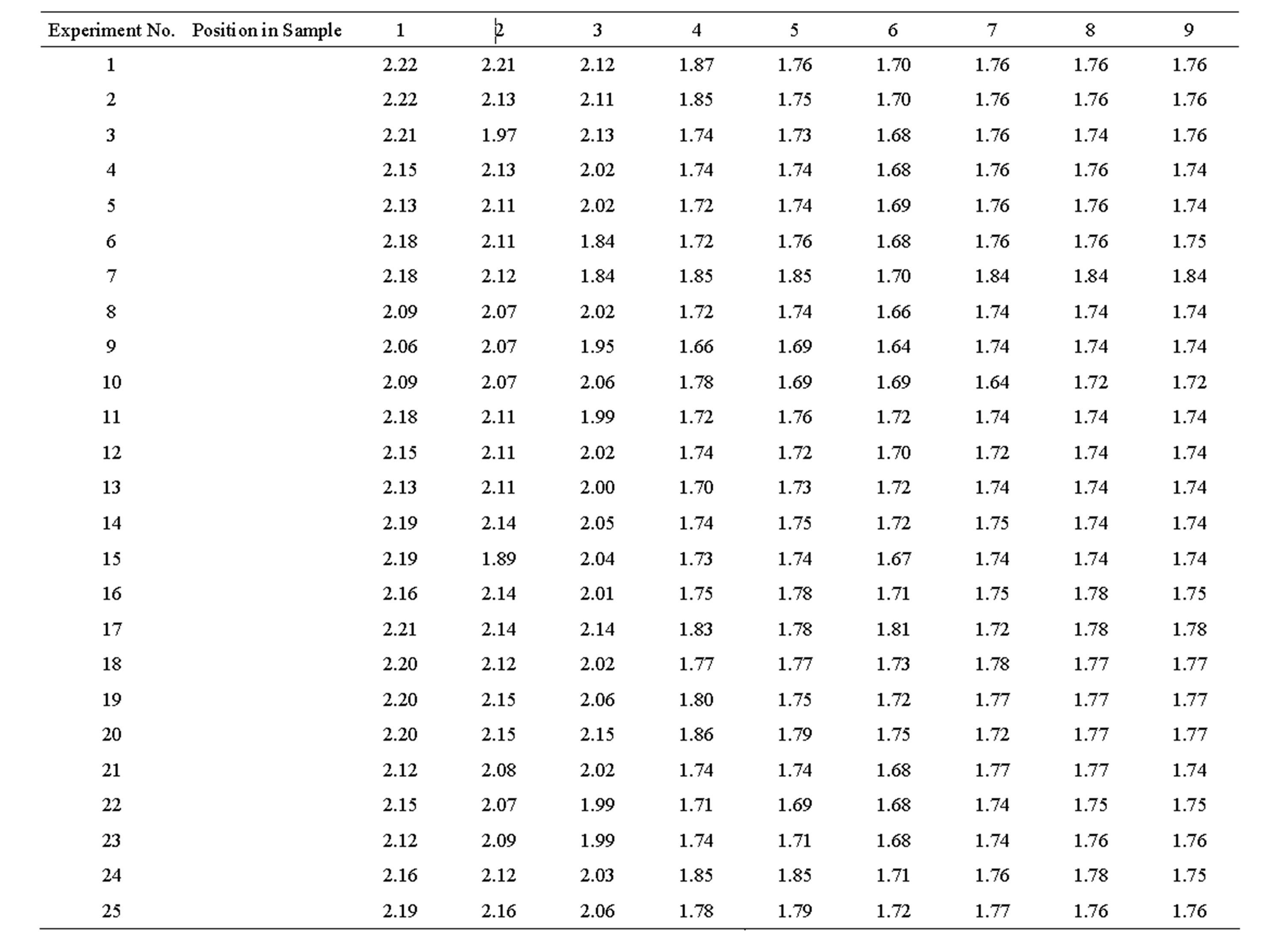
Table 3. Thickness measuring results from experiments (mm).
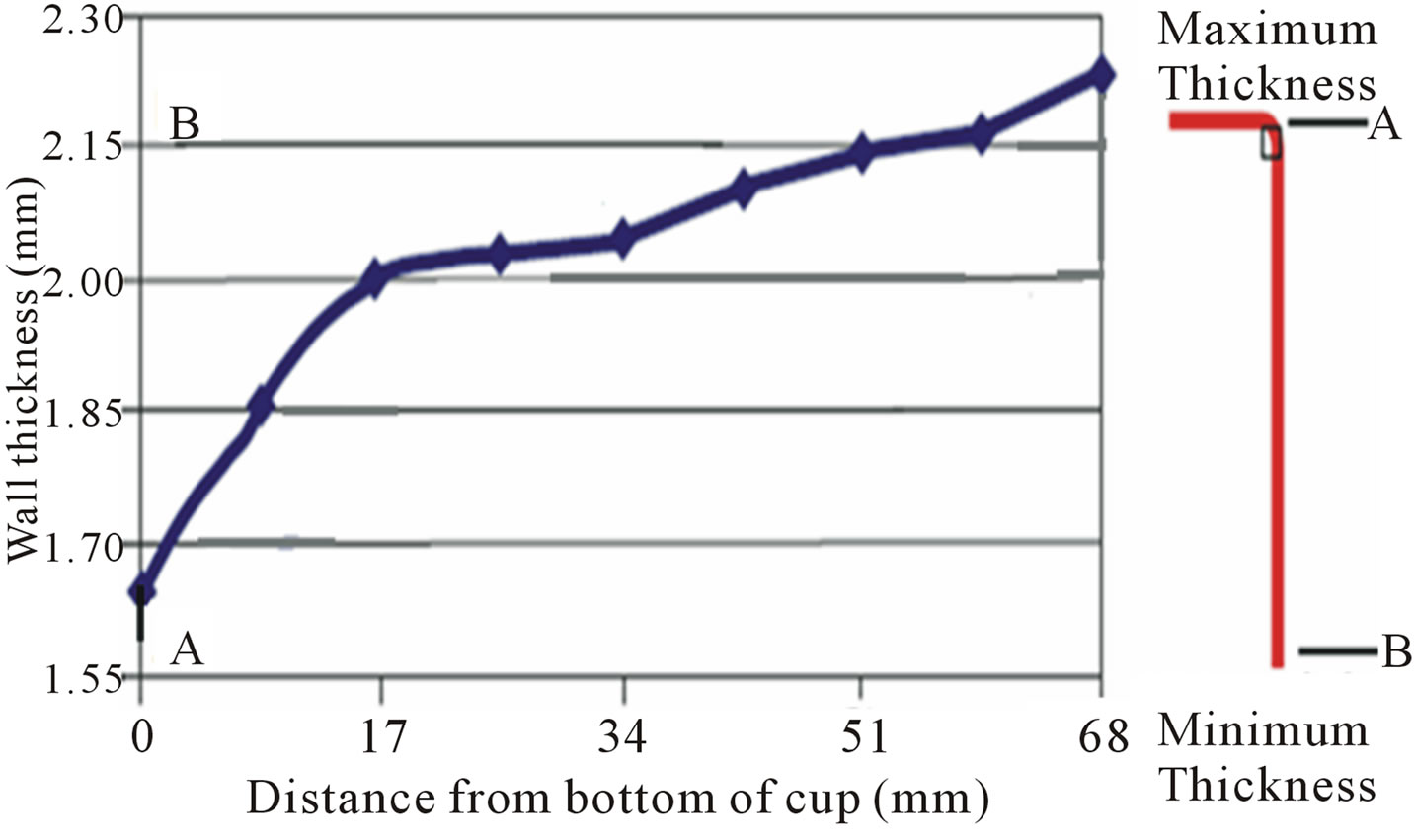
Figure 6. Schematic illustration of thickness changes in cup drawing Process according to table 3 and figure 3.
position 1 and it is next to 11% of blank thickness. The schematic thickness changes in a drawn cup during deep drawing process is shown in figure 6.
5. Conclusion
An analytical model to calculate the radial, circumference, thickness, and equivalent strains of drawn cup has been developed by taking into account work hardening effect. Experiments were conducted to evaluate theoretical analysis. The results of them are in agreement with theoretical results. The analysis is useful for the prediction of thickness variation of the products prior to the carryout of the actual drawing process. The analysis may be used to estimate the critical thickness that initiates the failure of the products and also to set the minimum clearness between the die and punch for the consequent ironing process.
REFERENCES
- H. Sattari, R. Sedaghati and R. Ganesan, “Analysis and Design Optimization of Deep Drawing Process. Part 1. Three Dimensional Finite Element and Sensitivity Analysis,” Journal of Materials Processing Technology, Vol. 184, No. 1-3, 2007, pp. 84-92. http://dx.doi.org/10.1016/j.jmatprotec.2006.11.008
- B. Kroplin and E. Luckey “Metal Forming Process Simulation in Industry,” International Conference and Workshop, Baden, 1994, pp. 28-30.
- J. K. Lee, G. L. Kinzel and R. Wagoner, “Numerical Simulation of 3D Sheet Metal Forming Processes, Verification of Simulations with Experiments,” 3rd International Conference on NUMISHEET 96, the Ohio State University, Dearborn, 29 September-3 October 1996, pp. 128- 135.
- J. C. Gerdeen and P. Chen, “Geometric Mapping Method of Computer Modeling of Sheet Metal Forming,” NUMISHEET 89, Seoul, 23 June 1989, pp. 437-444.
- K. Chung and D. Lee, “Computer-Aided Analysis of Sheet Material Forming Processes,” 1st International Conference on Technology of Plasticity, Vol. 1, Tokyo, 1984, pp. 660-665.
- M. P. Sklad and B. A. Yungblud, “Analysis of Multioperation Sheet Forming Processes,” NUMISHEET 92, Sophia Antipolis, 13-18 September 1992, pp. 543-547.
- K. Chung and O. Richmond, “Sheet Forming Process Design on Ideal Forming Theory,” NUMISHEET 92, Sophia Antipolis, 13-18 September 1992, pp. 455-460.
- J. L. Batoz, P. Duroux, Y. Q. Guo and J. M. Detraux, “An Efficient Algorithm to Estimate the Large Strains in Deep Drawing,” NUMISHEET 89, Seoul, 23 June 1989, pp. 383-388.
- J. L. Batoz, H. Naceur, O. Barlet, Y. Q. Guo and C. Knopf-Lenoir, “Optimum Design of Blank Contours in Axi-Symmetrical Deep Drawing Process,” In: Z. WanXie, C. Geng-Dong and X.-K. Li, Eds., Advances in Computational Mechanics, International Academic Publisher, Beijing, 1996, pp. 113-125.
- Y. Q. Guo, J. L. Batoz, H. Naceur, S. Bouabdallah, F. Mercier and O. Barlet, “Recent Developments on the Analysis and Optimum Design of Sheet Metal Forming Parts Using a Simplified Inverse Approach,” Computers & Structures, Vol. 78, No. 1-3, 2000, pp. 133-148. http://dx.doi.org/10.1016/S0045-7949(00)00095-X
- H. Naceur, A. Delameziere, J. L. Batoz, Y. Q. Guo and C. Knopf-Lenoir, “Some Improvements on the Optimum Process Design in Deep Drawing Using the Inverse Approach,” Journal of Materials Processing Technology, Vol. 146, No. 2, 2004, pp. 250-262. http://dx.doi.org/10.1016/j.jmatprotec.2003.11.015
- O. Barlet, J.-L. Batoz, Y. Q. Guo, F. Mercier, H. Naceur and C. Knopf-Lenoir, “The Inverse Approach and Mathematical Programming Techniques for Optimum Design of Sheet Forming Parts,” ESDA 96’, 3rd Biennial European Joint Conference on Engineering Systems Design and Analysis, Montpellier, Vol. 3, 1-4 July 1996, pp. 227-232.
- X. Chateau, “A Simplified Approach for Sheet Forming Processes Design,” International Journal of Mechanical Sciences, Vol. 36, No. 6, 1994, pp. 579-597. http://dx.doi.org/10.1016/0020-7403(94)90033-7
- G. Dhatt, G. Touzot and S. A. Maloine, “Unepresentation de la Methode des Elements Finis,” L’Universit´e Laval Qu´ebec, Paris, 1981.
- J. L. Batoz and G. Dhatt, “Modelisation des Structures Par Elements Finis, Vol. 3,” Coques, Ed., Hermes, Paris, 1992.
- E. Onate, M. Kleiber and C. Agelet de Saracibar, “Plastic and Viscoplastic Flow of Void-Containing Metals. Applications to Axisymmetric Sheet Forming Problems,” International Journal for Numerical Methods in Engineering, Vol. 25, No. 1, 1988, pp. 227-251. http://dx.doi.org/10.1002/nme.1620250118
- H. Matthies and G. Strang, “The Solution of Nonlinear Finite Element Equations,” International Journal for Numerical Methods in Engineering, Vol. 14, No. 11, 1979, pp. 1613-1626. http://dx.doi.org/10.1002/nme.1620141104
- D. R. J. Owen and E. Hinton, “Finite Elements in Plasticity: Theory and Practice,” Pineridge Press, Swansea, 1980.
- D. Peric, D. R. J. Owen and M. E. Honnor, “Simulation of Thin Sheet Metal Forming Processes Employing a Thin Shell Element. FE Simulation of 3-D Sheet Metal Forming Processes in Automotive Industry,” VDI Verlag, Zurich, 1991, pp. 569-600.
- H. D. Hibbitt, P. V. Marcal and J. R. Rice, “A Finite Element Formulation for Problems of Large Strain and Large Displacement,” International Journal of Solids and Structures, Vol. 6, No. 8, 1970, pp. 1069-1086. http://dx.doi.org/10.1016/0020-7683(70)90048-X
- R. M. McMeeking and J. R. Rice, “Finite-Element Formulations for Problems of Large Elastic-Plastic Deformation,” International Journal of Solids and Structures, Vol. 11, No. 5, 1975, pp. 601-616. http://dx.doi.org/10.1016/0020-7683(75)90033-5
- K. Washizu, “Variational Methods in Elasticity and Plasticity,” 3rd Edition, Pergamon Press, Oxford, 1982.
- E. H. Lee, “Elastic-Plastic Deformation at Finite Strains,” Journal of Applied Mechanics, Vol. 36, No. 1, 1969, pp. 1-6. http://dx.doi.org/10.1115/1.3564580
- T. J. Chung, “Continuum Mechanics,” Prentice Hall, Upper Saddle River, 1988.
- J. S. Arora, “Introduction to Optimum Design,” McGrawHill, New York, 1989.
- G. N. Vanderplaats, “Numerical Optimization Techniques for Engineering Design with Applications,” McGraw-Hill Inc., New York, 1984.
- B. H. V. Topping and D. J. Robinson, “Selecting Non- Linear Optimization Techniques for Structural Design,” Engineering Computations, Vol. 1, No. 3, 1984, pp. 48- 54.
- B. Prasad and R. T. Haftka, “Optimal Structural Design with Plate Finite Elements,” Journal of the Structural Division, Vol. 105, No. 11, 1979, pp. 2367-2382.
- E. Rohan and J. R. Whiteman, “Shape Optimization of Elastoplastic Structures and Continua,” Computer Methods in Applied Mechanics and Engineering, Vol. 23, 2000, pp. 68-76.
- Steel Solution, Deep Drawing, 2010. www.arcelormittal.com/
- E. I. Semenov, “Handbook of Sheet Metal Forming,” Machinery-Building, Moscow, 1983.
- V. P. Romanovski, “Handbook of Cold Stamping,” Machinery-Building, Moscow, 1979.
- Y. T. Kenum, C. T. Wang, M. J. Saran and R. H. Wagner, “Practical Die Design via Section Analysis,” Journal of Material Processing Technology, Vol. 35, No. 1, 1992, pp. 1-36. http://dx.doi.org/10.1016/0924-0136(92)90299-8
- E. A. Popov, “Foundations of Sheet Metal Forming Theory,” Machinery-Building, Moscow, 1977.
- E. A. Popov and V. G. Kovalyov, “Technology of Sheet Metal Forming,” Bauman MSTU Publication, Moscow, 2003.
- M. V. Storoschev and E. A. Popov, “Theory of Metal Forming Proceeding,” Machinery-Building, Moscow, 1977.
- W. F. Hosford, “The Mechanics of Crystals and Polycrystals,” Oxford University Press, USA, 1993.
- S. Y. Chung and H. W. Swift, “Cup Drawing from a Flat Blank, Part II, Analytical Investigation,” Proceeding of the Institution of Mechanical Engineers, London, June 1951, pp. 211-228.
- D. M. Woo, “On the Complete Solution of a Deep-Drawing Problem,” International Journal of Mechanical Science, Vol. 10, No. 2, 1968, pp. 83-94. http://dx.doi.org/10.1016/0020-7403(68)90065-9
- S. M. Mahdavian and D. He, “Product Thickness Analysis in Pure Cup Drawing,” Journal of Material Processing Technology, Vol. 51, No. 1-4, 1995, pp. 387-406. http://dx.doi.org/10.1016/0924-0136(94)01586-P
- Z. Marciniak, J. L. Duncan and S. J. Hu, “Mechanics of Sheet Metal Forming,” Butterworth-Heinemann, Oxford, 2002
- W. F. Hosford and R. M. Caddel, “Metal Forming, Mechanic and Metallurgy,” 3rd Edition, Cambridge University Press, Cambridge, 2007.
- E. Nazaryan and V. Konstantinov, “Kinematics of Straining in Deformation Operations of Sheet Stamping,” Bulletin of Machine-Building, Vol. 2, 1999, pp. 35-41.
- N. Arab and E. Nazaryan, “Modeling Deep Drawing of Cylindrical Cup,” International Journal of Applied Engineering Research, Vol. 4, 2009, pp. 2487-2496.
- N. Arab, “New Theoretical Calculation of Limit Drawing Ratio by Taking into Account Material Parameters Changes during Deep Drawing of Cylindrical Cup,” International Journal of Theoretical and Applied Mechanics, Vol. 5, 2010, pp. 139-146.
- N. Arab, E. Nazaryan, M. Arakelyan, and A.Markosyan, “Mechanics of Forming Thin Ring Plates,” IDDRG International Conference, Golden, 1-3 June 2009, paper code C/66/09.
- N. Arab and E. Nazaryan, “Stress and Strain Paths in Deep Drawing of Cylindrical Cup,” International Research Journal of Engineering Science, Technology and Innovation (IRJESTI), Vol. 2, No. 3, 2013, pp. 51-56.