Open Journal of Fluid Dynamics
Vol.05 No.01(2015), Article ID:54552,7 pages
10.4236/ojfd.2015.51009
Impact of the Housing on the Air Flow and the Thermal Behavior of an Automotive Clutch System
Anthony Levillain1,2*, Pascale Brassart1, Béatrice Patte-Rouland2
1VALEO Transmissions, Centre d’Etudes des Produits Nouveaux, rue de Poulainville, Amiens, France
2CORIA UMR 6614, Avenue de l’université, Saint-Etienne du Rouvray, France
Email: *levillain.anthony@orange.fr
Copyright © 2015 by authors and Scientific Research Publishing Inc.
This work is licensed under the Creative Commons Attribution International License (CC BY).
http://creativecommons.org/licenses/by/4.0/


Received 14 February 2015; accepted 5 March 2015; published 11 March 2015
ABSTRACT
New directives and increasing competition push automakers to get better performances (engine power increase), along with mass and size reduction (consumption). These evolutions lead to an increase of the thermal solicitations undergone by the automotive clutches whereas their weight must be decreased, as it is one of the main influent factors on CO2 emissions. Previous studies only focused on the air flow created by the clutches, but none of them have shown the impact of the clutch housing on the cooling of the clutch parts. In order to determine the influence of the clutch housing on the thermal behavior of automotive clutch systems, a numerical study has been performed on a simplified model of a clutch system. A parametric variation has been performed on the clutch housing size in order to evaluate its impact on the flow and the thermal behavior of clutches. The results show that clutch housing has a significant impact on the air flow and the thermal behavior of clutches. Thermal tests on real clutches with and without clutch housing have confirmed these results.
Keywords:
Clutch, Thermal Simulations, CFD, Air Flow, Convection

1. Introduction
Automotive clutches are rotating systems subject to high heat load. These heat loads are generated by the slipping of a Cast Iron Disc, rotatable with the engine, and a facing disc, rotatable with the gearbox shaft. Both parts are rotating at different speeds, depending on engine speed and engaged gear ratio. While engaging clutch, the parts slip on each other before being fully engaged, and heat is generated. These heat loads may be significant during traffic jam start-ups or hill starts. The cooling of the cast iron disc is directed mainly by the convection as it has been shown on previous study [1] . The heat is exchanged by convection with the air enclosed in the clutch housing.
Previous studies on transmission clutches thermal behavior have not been focused on the impact of the clutch housing on convective heat transfer. H. Beitler [2] made an experimental study of clutches without clutch housing, which combined air flow rate and temperature measurements. He mainly used the assumption that air flow rates were directly proportional to heat transfer coefficients. S. Wittig et al. were the first, to the knowledge of the authors, to apply a CFD model on clutches [3] . They used simplified model with clutch housing and evaluated the impact of holes locations in the clutch system. J. Hauschild [4] performed a CFD study on a real clutch in its environment, and has shown that heat transfer is mainly related to air flow rate.
In order to evaluate the impact of the clutch housing on the air flow rate and the convective heat transfer exchange, a CFD study is proposed. The clutch geometry has been abstracted to a simple model involving only the Cast Iron Disc and the Cover parts (Figure 1). In order to get quick results for a more in-depth study, only 2D model is considered.
2. Numerical Procedure
The first point was to determine which model is the most accurate for such rotating systems. Results obtained from a commercial CFD code have been compared with previous air flow measurements made on a rotor-stator confined system [5] . The results have shown that the model could give accurate results for rotating flows [6] .
The clutch geometry has been abstracted to a simple model involving only the Cast Iron Disc and the Cover parts. In order to get quick results for a more in-depth study, only 2D-axisymmetric model is considered. In the rest of the study, the Cast Iron Disc will be referred as Disc.
The Disc radius is  while the Cover inner radius is
 . The parts width are
  and
and  for the Disc and the Cover, respectively. The axial distance between Disc and Cover is d = 4 mm. A clutch housing, centered with the Disc, is used. Varying parameters are radius
  and axial length L of the clutch housing. The used values can be found in Table 1.
Regarding the mesh, tetrahedral elements have been considered in the bulk flow, while boundary layers have been meshed with square elements. The objective is a  value below 4 in the boundary layers regions [7] . A mesh convergence has been performed to get results independent of the grid size.

Figure 1. Numerical model simplifications.

Table 1. Clutch housing size.
A single reference frame rotating at 1000 rpm is used to take into account the rotation of the simplified clutch. Thermal boundary conditions have been set at  on the Disc, while the clutch housing and the Cover have been set at
 .
.
3. Results
3.1. Flow Rates
Flow rates data are collected from the surface  (Figure 1). Table 2 shows results obtained for the four selected cases. As it is 2D computation, the equivalent 3D volume of the clutch housing is computed such as:
 (1)
(1)
The flow rates are plotted in Figure 2 as a function of the equivalent domain volume. It can be seen that the flow rate increases with the domain volume. For high values of domain volume, i.e., when the clutch housing size tends to an opened system, an asymptotic behavior can be noticed. It means that from a given clutch housing size, the latter does not have any impact on the flow rate inside the clutch system.
This behavior can also be observed on the radial velocity profiles of the fluid between the Disc and the Cover. Figure 3 represents the air flow radial velocity at a radius . For small clutch housing size, the radial boundary layers are separated. For a clutch housing size of 240 mm, the radial velocity profile at the center of the cavity increases from a value close to zero to a value of approximately 1.25 m∙s−1. As domain volume increases, this velocity increases. For a clutch housing size of 360 mm, the two radial boundary layers have merged and their amplitude has grown. This phenomenon can be explained by the static pressure. A pressure difference is computed by Equation (2):
 (2)
(2)
where  is the static pressure at the entrance of the system and
  is the static pressure at the exit of the system (Figure 1). This pressure difference evolution is plotted in Figure 2. It can be noticed that the pressure difference decreases with the domain volume and tends to zero. It can be explained by the fact that:
The more the radial clutch housing size decreases, the more the flow is restricted at the exit of the clutch system. Thus, an overpressure can be observed at the exit . On the other hand, the more the axial clutch housing size decreases, the more the depression at the entrance of the system is large. Then, for small clutch size, the relative static pressure becomes, with
  the atmospheric pressure:
 (3)
(3)
 (4)
(4)
and the pressure difference increases. For a clutch housing size that tends to infinity, this difference decrease until
 (5)
(5)
Then, the clutch housing size will impact the static pressure, creating depression and overpressure for small clutch housing size. The latter will restrict the fluid flow within the system and reduce the air flow rates.
3.2. Heat Transfer
The convective heat transfer is computed for the Disc face in front of the Cover  (Figure 1). The heat flux
Table 2. Flow rates data.

Figure 2. Flow Rates, Static Pressure and Heat transfer.
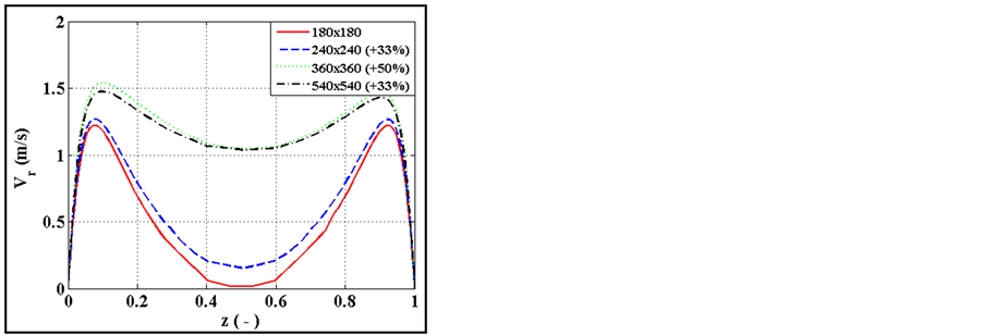
Figure 3. Radial velocity profile at r = 100 mm.
is computed by the Equation (6) and is plotted as a function of the local radius of the Disc in Figure 4.
 (6)
(6)
Looking at the local heat flux, three different parts can be seen for each case:
・ for : the heat flux is almost constant along this disc part.
・ for : the heat flux increases to its max value. This part corresponds to the entrance of the system. At this location, the air flow suction created by the rotation of the disc and the Cover is the highest, as the axial velocities increase slightly in this area. Radial velocities increase also as flow rate is preserved. This can be seen on Figure 5 where contour of 2D plane velocity magnitude
 , defined in Equation (7), is plotted for Case 1, where
  and
and . Furthermore, fresh air flow coming from the outside of the system get in the channel between the Disc and the Cover.
 (7)
(7)
・ for : This part corresponds to a case of a co-rotating system, with the rotation of the Disc
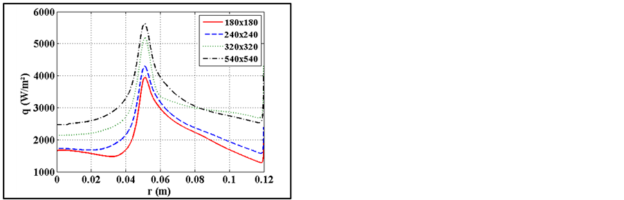
Figure 4. Heat flux q (W/m2) on the Disc surface SDisc.

Figure 5. Contours of velocity magnitude  (m/s).
in front of the Cover, both at same speed. A decrease of the heat flux can be noticed. This behavior can be explained by the fact that air flow temperature inside this channel increases linearly with the radius coordinate (Figure 6). The air temperatures tend to an equilibrium, where the temperatures from the Disc to the Cover decreases linearly. Then, heat flux will tend to a value such as:
 (8)
(8)
In this case, . Furthermore, the heat flux decrease is higher with small clutch housing size. The slope of this decrease is related to the air flow rate between the Disc and the Cover. The higher the flow rate, the slower the heat flux decrease, as fresh air is renewable quickly with high flow rates.
Then, as the temperature between the Disc and the Cover has a great impact on thermal behavior, the convective heat transfer coefficient is computed with the midline temperature  as shown in Equation (9).
 (9)
(9)
The global heat transfer coefficient is then computed by Equation (10) and is plotted in Figure 2.
 (10)
(10)
where  is the equivalent surface of the Disc face in front of the Cover.
Then, as seen previously with the heat flux, the heat transfer coefficient increase with the clutch housing size. An asymptotic behavior can be noticed when clutch housing is above a size of 360 mm. This asymptotic behavior is in accordance with the air flow rate.
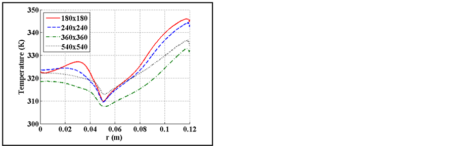
Figure 6. Temperature between the disc and the cover.
4. Validation
In order to validate this study, thermal test bench has been performed on clutches with and without clutch housing. Clutch is heated by slippage on test bench, where slip speed  between the Facing Disc and the Cast Iron Disc, together with the torque
 , can be controlled. Input Power
  can then be adjusted. A temperature inside the Cast Iron Disc is then measured with a type-K thermocouple with a 10 Hz frequency.
Clutch is heated until a stabilized temperature is reached. Then clutch is fully engaged and a constant rotating speed is used on both parts (no slip). Clutch is cooled to the ambient temperature. This procedure is used at different rotating speeds.
Considering the Cast Iron Disc is such that its temperature is uniform during the cooling process, the temperature during this phase can be written such as:
 (11)
(11)
The latter Equation (11) can be written in a discretized form such as:
 (12)
(12)
Then, in order to determine a global convective coefficient of the clutch Cast Iron Disc, the convective coefficient h of the previous Equation (12) must be found. Knowing the mass M, the specific heat of the material  and the surface of the Cast Iron Disc
 , the convective coefficient h can be determined, varying its value on a predefined estimated range (denoted n). The retained value is obtained by minimizing the quadratic error defined by Equation (13):
 (13)
(13)
where  is the measured temperature of the cooling on test bench, and
  is the computed temperature obtained with Equation (12). The results obtained with this convective coefficient estimation procedure are plotted on Figure 7. As expected, clutch convective coefficient with clutch housing is lower than without clutch housing.
5. Conclusions
In this study, clutch housing impact on the clutch parts cooling was evaluated. First, it has been shown that the clutch housing has a significant impact on the flow rates between the Cover and the Disc. This phenomenon is explained by the static pressure in the system. Looking at the thermal behavior of the system, three different heat transfer profiles appear on the Cast Iron Disc:
・ Constant heat flux at small radius.
・ Heat flux peak at the system entrance, due to air suction. As clutch housing size increases, flow rates increase and heat transfer is improved.

Figure 7. Experimental convective coefficients.
・ Heat flux linear decreases between the Disc and the Cover, due to air temperature increase. The heat flux decreasing is smaller with high air flow rates.
The sum of these results is a global heat transfer increase with clutch housing size. Heat transfer is related to air flow rate. An asymptotic behavior has been noticed when clutch housing is large enough, and pressure differential tends to zero.
This study has shown that the clutch housing has a significant impact on clutches heat transfer. The results have been validated by thermal tests on real clutch with and without clutch housing. Then, next step is the evaluation of the impact of holes in the clutch housing. For such study, 3D CFD will be necessary in order to get the impact, for example, of holes location and size.
References
- Minereau, H. (1988) Contribution à l’étude des transferts thermiques dans l’embrayage. C.N.A.M, Paris, 237 p.
- Beitler, H. (2008) Analysis of the Temperature and Heat Output Characteristic of a Single-Plate Dry Clutch. KIT PhD Thesis, Karlsruhe University, Karlsruhe.
- Wittig, S., Kim, S., Scherer, T.H. and Weissert, I. (1998) Numerical Study for Optimizing Heat Transfer in High Speed Rotating Components. International Journal of Rotating Machinery, 4, 151-161. http://dx.doi.org/10.1155/S1023621X9800013X
- Hauschild, J. (2012) Analysis of Manual Dry Clutch Temperature Behavior and System Requirements. VDI 2012.
- Itoh, M., et al. (1992) Experiments on Turbulent Flow Due to an Enclosed Rotating Disk, Exp. Thermal and Fluid Science, 5, 359-368. http://dx.doi.org/10.1016/0894-1777(92)90081-F
- Levillain, A., Brassart, P., Demare, D. and Patte-Rouland, B. (2014) Validation d'un modèle CFD Thermique pour un système de Double Embrayage à Sec., Congrès Français de Thermique 2014, 3-6 Juin 2014, Lyon.
- (2009) ANSYS Fluent 12.0, “Theory Guide”.
Nomenclature
 : disc radius (m);
 : entrance radius (m);
 : clutch housing radius (m);
 : disc width (m);
 : Cover width (m);
 : distance between Disc and Cover (m);
 : clutch housing axial length (m);
 : Equivalent surface of the Disc face (m2);
 : Surface at the Entrance (m2);
: equivalent volume of the clutch housing (m3);
 : axial coordinates (m);
 : radial coordinates (m);
 : axial fluid velocity (m/s);
 : radial fluid velocity (m/s);
 : 2D plane velocity magnitude (m);
 : Disc surface temperature (K);
 : Cover surface temperature (K);
 : Clutch housing surface temperature (K);
 : midline temperature (K);
 : Ambient measured temperature (K);
 : Cast Iron Disc measured temperature (K);
 : computed temperature (K);
 : volume flow rate (m3/s);
 : heat transfer coefficient (Wm2/K/);
 : heat flux (W/m2);
 : Static pressure (Pa);
 : air thermal conductivity (W/m/K);
 : Torque (N.m);
 : rotating speed (rpm);
 : specific heat (J/kg/K);
 : mass (kg).
NOTES

*Corresponding author.