Open Journal of Fluid Dynamics
Vol.2 No.4A(2012), Article ID:25816,7 pages DOI:10.4236/ojfd.2012.24A027
Computational Study on Micro Shock Tube Flows with Gradual Diaphragm Rupture Process
1Department of Mechanical Engineering, Andong National University, Andong, South Korea
2Institute of Ocean Technology, Saga University, Saga, Japan
Email: *kimhd@andong.ac.kr
Received September 12, 2012; revised October 24, 2012; accepted November 3, 2012
Keywords: Diaphragm Rupture; Expansion Wave; Micro Shock Tube; Rarefaction; Unsteady Flow
ABSTRACT
Gas flows through micro shock tubes are widely used in many engineering applications such as micro engines, particle delivery devices etc. Recently, few studies have been carried out to explore the shock wave excursions through micro shock tubes at very low Reynolds number and at rarefied gas condition. But these studies assumed centered shock and expansion waves, which are generally produced by instantaneous diaphragm rupture process. But in real scenario, the diaphragm ruptures with a finite rupture time and this phenomenon will significantly alter the shock wave propagation characteristics. In the present research, numerical simulations have been carried out on a two dimensional micro shock tube model to simulate the effect of finite diaphragm rupture process on the wave characteristics. The rarefaction effect was simulated using Maxwell’s slip wall equations. The results show that shock wave attenuates rapidly in micro shock tubes compared to conventional macro shock tubes. Finite diaphragm rupture causes the formation of non-centered shock wave at some distance ahead of the diaphragm. The shock propagation distance is also drastically reduced by the rupture effects.
1. Introduction
Shock tube is a device which generates a moving shock front and associated expansion and contact waves, by the sudden expansion of gas from high pressure to a low pressure region. This moving shock front produces high speed and high temperature flow fields which are recently employed in many micro devices, using micro shock tubes. The flow field in a conventional shock tube was extensively studied and documented in many of the past works [1,2]. But as the flow dimension reduces the Reynolds number decreases and leads to more prominent viscous effects. This leads to attenuation of shock strength and eventually leads to less propagation distance. Shock wave also suffers attenuation as the initial operating pressure reduces. This has been pointed out by the experimental studies conducted by Brouillette [3] on a shock tube of 5.3 mm diameter. They established a scaling factor which relates the diameter and initial pressure dependency on shock propagation.
Another important effect associated with micro scale flows are rarefaction effects. The effect of rarefaction on a low speed micro channel flows have been widely studied in the past. Karniadakis [4] provided detailed information on such rarefied fluid dynamics at low speed. It is also well known that the near wall fluid slips as the flow becomes rarefied. But the effect of rarefaction in high speed flows, such as in the case of shock tubes, have got little attention in the past. The initial effort to study the effect of rarefaction on micro shock tube flows was carried out by Zeiton [5,6]. There numerically study showed that the shock propagation distance increases due to the slip effects.
But these studies on micro shock tube assumed an instantaneous opening of diaphragm which produces centered expansion and shock wave. But in real case, the diaphragm ruptures gradually and the flow evolves from the high pressure chamber to the low pressure chamber progressively. This produces non centered waves in the shock tube and the propagation characteristics of the wave shows differences compared to the sudden rupture process. A series of compression waves will be produced in this process and the flow field near the diaphragm becomes extremely complex.
The main complexity associated with the simulation of diaphragm rupture is to identify the actual rupture process. The research done by Hickman [7] proposed that the diaphragm initially bulges and then the rupture initiates at the diaphragm center. He also developed a mathematical relation to quantify the opening area with respect to the strength parameter of the diaphragm. Later Outa [8] proposed a cosine opening function for the diaphragm opening radius with respect to time. Recently, Matsuo [9] assumed a quadratic opening function for the opening radius with respect to time for their shock tube studies to determine the diaphragm rupture effects at different pressure ratios. They also performed experimental studies to determine the rupture time at different pressure ratios for a shock tube of 65.5 mm diameter.
In the past there have been some studies to mathematically model the diaphragm rupture process and its effect on macro shock tube flow fields [10,11]. But in the case of micro shock tubes the unsteady shock evolution and the associated flow field with a finite diaphragm rupture process is even more complicated due to the slip and boundary layer effects. However, to the author’s knowledge, there is no CFD study to simulate this effect on micro shock tube flows to date.
In the present study a 2D axi-symmetric CFD approach was used to simulate the unsteady flow evolution and shock propagation inside a micro shock tube considering the diaphragm rupture process. Three different mathematical functions were used to replicate the rupture process and were compared with the experimental data provided by Matsuo, to obtain the optimum opening function. The optimum opening function obtained from the macro shock tube studies were later used to simulate the diaphragm rupture process for micro shock tube.
2. Numerical Simulation
2.1. Computational Domain
For the present study an axi-symmetric shock tube model of 3 mm diameter was considered as shown in Figure 1.
2.2. Mesh Independence Study
The numerical simulation results have a strong dependency on mesh quality and distribution. So to optimize the grid for reducing the numerical errors, a mesh independence study was carried out. For mesh independence study, four different grids were considered for the simulation with same pressure ratio (P4/P1) of 100 and with initial driven pressure of 100 Pa. The static temperature distributions along the axis for different mesh simulations were compared and are shown in Figure 2. The fourth mesh which is not producing much deviation in results from its preceding mesh was used for all the future studies.
2.3. Governing Equations
The flow physics was mathematically modeled using unsteady Reynolds Averaged Navier-Stokes equations.
Figure 1. Schematic diagram for micro shock tube (ϕ3 mm).
Figure 2. Static temperature distributions along center line at t = 10 µs on different grids.
The governing equations in the cartesian form can be written asContinuity
 (1)
(1)
Momentum
 (2)
(2)
Energy
 (3)
(3)
τeff is the shear stress tensor which is modeled as,
 (4)
(4)
The shock disturbance produces flow fluctuations to the downstream boundary layer which makes the flow either transitional or turbulent, even though the diameter is very small. SST k-ω model was used to predict the turbulent eddies. In this model the turbulent viscosity is calculated by solving the transport equation for turbulent kinetic energy (k) and the specific dissipation rate (ω) as shown in the below equation.
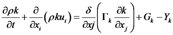 (5)
(5)
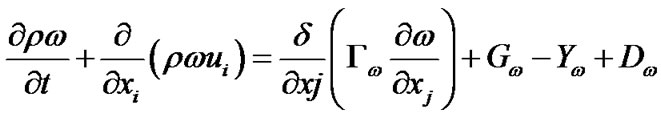 (6)
(6)
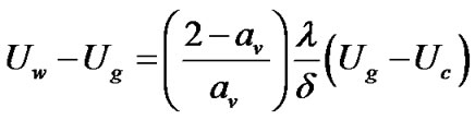
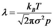
The working gas was considered to obey ideal gas law. The flux component of the governing equation was discretized using AUSM scheme. A second order implicit scheme was used for the temporal discretization. The extrapolation of cell centre values to the face centers was done using third order MUSCL schemes. The governing flow equations were solved in a coupled manner using commercial solver, Fluent. To account for the rarefaction effects which happen at low pressure Maxwell’s slip velocity and temperature jump equations, as shown below, were employed. User defined functions were used to input these equations to the solver and subsequent to each flow iteration the pre defined functions for slip conditions were called into the solver and executed to update the near wall fluid velocity and temperature.
 (7)
(7)
 (8)
(8)
 (9)
(9)
Here the subscript g, c and w refer to gas, cell centre and wall quantities respectively. av and at are the momentum and thermal accommodation coefficients respectively. λ is the molecular mean free path.
2.4. Gradual Diaphragm Rupture Modeling
To replicate the gradual diaphragm rupture process, the total diaphragm radius was divided into thirty segments. Each segment length was determined using some mathematical function which relates the opening radius at each opening time intervals. Three cases were simulated with different opening functions as shown below, to determine the accuracy of different opening processes.
Linear Opening:
 (10)
(10)
Cosine Opening (by Outa):
 (11)
(11)
Quadratic Opening (Matsuo):
 (12)
(12)
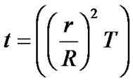
The simulation results were compared to the experimental study carried out by Matsuo on a shock tube of 65.5 mm diameter and pressure ratio of 2. In the experiment, pressure variations in the driver section at a location 150 mm downstream of the diaphragm were monitored. Figure 3 shows the comparison of the pressure distributions obtained from the numerical studies with different diaphragm opening process to the experimental value. The operating condition details for different cases are shown in Table 1. It can be noticed that the quadratic opening functions shows much closer result compared to the experiment and is used for modeling the rupture process for all future studies.
Other opening processes using the cosine and linear functions shows a much deviation from the experimental pressure values. This may be due to the fact that the initial diaphragm opening process for these functions

Table 1. Initial conditions for different opening functions.
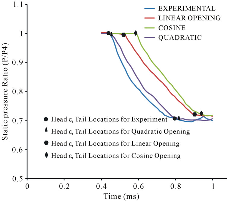
Figure 3. Static pressure comparisons in the driver section for different cases at X/D = −2.29.
produces a slow rupture process where as for quadratic the initial rupture process will be rapid. Due to this reason the flow evolution will be slower for the cosine as well as the linear functions and produce deviations in the pressure values. This can be clearly noticed from Figure 4, which shows the diaphragm opening radius for different functions at various times.
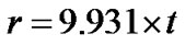
The present research focuses on diaphragm rupture effects on micro shock tube flows. For the current study, the rupture time for a micro shock tube of 3mm diameter was derived from the experimental study on a conventional macro shock tube by Matsuo, using a linear interpolation technique as discussed below.
The diaphragm rupture time mainly depends on three factors such as diaphragm area, net pressure (P4-P1) acting across the diaphragm, diaphragm thickness.
It was assumed that the diaphragm ruptures mainly due to the external force used to rupture the diaphragm. The pressure forces acting across the diaphragm will be considerably small due to lower operating pressure. In the experimental study the diaphragm was ruptured using an external force provided by a needle. So this assumption holds good for the present case considered. Since the diaphragm rupture force and thickness are now same for macro as well as micro shock tubes, the total rupture time will depends only on the rupture area. It was also assumed that the diaphragm rupture time obeys a direct relationship with rupture area. By using this relation the rupture time for a 3 mm shock tube can be easily found out from the experimental 65.5 mm shock tube result and is found to be 0.45 μs.
3. Results and Discussion
For the current research a micro shock tube of 3 mm with a pressure ratio of 100 and driven pressure 100 Pa was considered. The very low pressure considered in the driven tube induces rarefaction effects which produce wall slipping effects. Two cases, one with slip wall and other with no-slip wall, were simulated to investigate the deviation in shock propagation characteristics under slip effects. All further investigations were carried out with slip conditions.
The very low pressure consideration in the driven section causes the Knudsen number to increase, 0.023 for the present case, which eventually makes the flow transitional where the wall attached fluid slips. The slip effects reduce the wall resistance to flow and helps in the propagation of shock front compared to no-slip condition. From Figure 5, which shows the static temperature distributions for slip and no slip case, the advantage in shock propagation for slip case can be clearly visualized. The previous studies conducted by the authors on a micro shock tube with suddenly ruptured diaphragm gives a
Figure 4. Diaphragm opening area variation with respect to time based on different opening functions.

Figure 5. Static temperature distributions for slip and no slip cases at t = 10 μs.
detailed discussion on the shock propagation characteristics under the slip flow [12].
For the unsteady diaphragm rupture case, due to the gradual rupture process of the diaphragm, the flow evolution into the driven section takes place gradually. This leads to the formation of several compression waves which will overtake each other and results to the formation of shock wave. The flow evolution process during the finite diaphragm rupture process is shown in Figure 6, using temperature contours at different opening times. From Figure 6, the development of contact surface and shock wave are clearly visible as a rise and dip in temperature values, respectively.
Because of the gradual opening consideration, a fully developed flow into the driven section takes some time. Due to this factor, the shock front will be generated after some particular distance ahead of the diaphragm where

Figure 6. Static temperature distributions in the driven section at different diaphragm opening stages.
as for a sudden rupture case an instantaneous production of shock front can be visualized. The temperature ratio across the shock is a direct indication for the shock strength and this is being compared along the length, as shown in Figure 7, which clearly explains the formation distance for shock front.
The ideal invicid shock tube equation explains that the shock strength will be a constant value. But for micro shock tubes, shock strength continuously attenuates due to viscous losses, finite diaphragm rupture process and turbulent losses. As a result of this the shock front with in a micro shock tube propagates much shorter distance compared to conventional macro shock tube.
Figure 8 shows the shock strength variation in a micro shock tube with sudden and gradual diaphragm rupture. The finite rupture effect causes further attenuation in shock strength compared to the sudden rupture case. This is because of the flow losses happening during the diaphragm rupture period.
Due to the reduction in shock strength for gradual rupture case compared to sudden rupture case, the shock propagation speed will be lesser for the former case and travels a much shorter distance at any particular time. Figure 9 shows the shock locations for sudden and gradual diaphragm rupture conditions at various times. The shock speed attenuation for gradual rupture case can
Figure 7. Static temperature ratio distributions across the shock front for quadratic diaphragm rupture process at various times.
Figure 8. Shock strength variations for sudden and gradual diaphragm rupture process at various times.

Figure 9. Shock location for sudden and gradual diaphragm rupture process along the center line.
be clearly visualized from this figure.
4. Conclusion
In the present study the effect of diaphragm opening process on the shock evolution and propagation with in a micro shock tube was studied using numerical techniques. Three different opening functions where chosen to replicate the diaphragm rupture process and the one with a quadratic opening function produce more reasonable matching with the experimental results. The finite diaphragm opening process causes a gradual flow evolution process during the initial rupture process. This leads to the development of compression waves which coalesces to form a moving shock front. Thus the shock front will be developed at a particular distance ahead of the diaphragm. The finite rupture process also causes a reduction in shock strength compared to the sudden rupture case. This reduces the shock speed and leads to a lesser shock propagation distance compared to sudden rupture case.
5. Acknowledgements
This work was supported by the National Research Foundation of Korea (NRF) grant funded by the Korea government (MEST) (2011-0017506).
REFERENCES
- I. I. Glass and J. P. Sislian, “Non Stationary Flows and Shock Waves, Oxford Science,” Oxford Science, New York, 1994.
- G. Rudinger and J. P. Sislian, “Wave Diagrams for NonSteady Flows in Ducts,” D. Van Nostrand Company Inc., Princeton, 1995.
- M. Brouillette, “Shock Waves at Microscales,” Shock Waves, Vol. 13, No. 1, 2003, pp. 3-12. doi:10.1007/s00193-003-0191-4
- G. E. M. Karniadakis and A. Beskok, “Micro Flows Fundamentals and Simulation,” Springer, New York, 2000.
- D. E. Zeitoun and Y. Burtschell, “Navier-Stokes Computations in Micro Shock Tubes,” Shock Waves, Vol. 15, No. 3-4, 2006, pp. 241-246. doi:10.1007/s00193-006-0023-4
- D. E. Zeitoun, Y. Burtschell, I. A. Graur, M. S. Ivanov, A. N. Kudryavtsev and Y. A. Bondar, “Numerical Simulation of Shock Wave Propagation in Microchannels using Continuum and Kinetic Approaches,” Shock Waves, Vol. 19, No. 4, 2009, pp. 307-316. doi:10.1007/s00193-009-0202-1
- R. S. Hichman, L. C. Farrar and J. B. Kyser, “Behavior of Burst Biaphragms in Shock Tubes,” Physics of Fluids, Vol. 18, No. 10, 1975, pp. 1249-1252. doi:10.1063/1.861010
- E. Outa, K. Tajima and K. Hayakawa, “Shock Tube Flow Influenced by Diaphragm Opening (Two-Dimensional Flow Near the Diaphragm),” 10th International Symposium on Shock Waves and Shock Tubes, Kyoto, 14-16 July 1975, pp. 312-319.
- S. Matsuo, M. Mohammad, S. Nakano and H. D. Kim, “Effect of Diaphragm Rupture Process on Flow Characteristics in a Shock Tube using Dried Cellophane,” Proceedings of the International Conference on Mechanical Engineering (ICME), Dhaka, 29-31 December, 2007.
- E. M. Rothkopf and W. Low, “Diaphragm Opening Process in Shock Tubes,” Physics of Fluids, Vol. 17, No. 6, 1974, pp. 1169-1173.
- E. M. Mizoguchi and S. Aso, “The Effect of Diaphragm Opening Time on the Feasibility of Tuned Operation in Free Piston Shock Tunnels,” Shock Waves, Vol. 19, No. 4, 2009, pp. 337-347.
- K. R. Arun, H. D Kim and T. Setoguchi, “Computational Study of Shock Wave Propagation and Reflection in a Micro Shock Tube,” 9th International Conference on Heat Transfer, Fluid Mechanics and Thermodynamics, Malta, 16-18 July 2012, pp. 1335-1340.
NOTES
*Corresponding author.