World Journal of Engineering and Technology
Vol.04 No.03(2016), Article ID:69735,10 pages
10.4236/wjet.2016.43045
Design and Development of Mechatronic Application in Agricultural Irrigation Device
Mohd Hudzari Razali*, Syazili Roslan, Abdul Ssomad Mohd Abd Halim, Hayan Basit
Faculty of Bioresources & Food Industry, Universiti Sultan Zainal Abidin, Tembila Campus, Besut, Terengganu Darul Iman, Malaysia

Copyright © 2016 by authors and Scientific Research Publishing Inc.
This work is licensed under the Creative Commons Attribution International License (CC BY).
http://creativecommons.org/licenses/by/4.0/


Received 3 February 2016; accepted 12 August 2016; published 15 August 2016
ABSTRACT
In order to help the small-scale farmer, an automatic irrigation control system was proposed. This system will provide an irrigation system that will ease the burden of the citizen to take care of the plant. This system will run automatically by referring to the time set by the user. As the name itself is a water control system, this system will only start irrigating when the time set triggered the water control level for the plant to grow healthily. It will automatically stop when the timer is off (1 hour). The brain of the system is the PLC (Programmable Logic Controller). This is the place where all the activities are done. The irrigation will be provided by a pump that is also connected to the microcontroller. The pump will be activated until the timer has reached its time set. This system will continue running until the user presses the OFF button.
Keywords:
Irrigation System, Water Control System, PLC (Programmable Logic Controller)

1. Introduction
As technology undergoes rapid advancement, complicated task such as control system is accomplished with a highly automated control system. Example of the system may be in the form of Programmable Logic Controller (PLC) and possibly a host computer and accompanied with signal interfacing to the field devices such as opera- tor panel, motors, sensors, switches, and solenoid valves. Network communication is capable of providing a large scale implementation and process coordination besides enabling greater versatility in understanding distributed control system. Every single integral component module in a control system plays a major role regardless of size. Generally, PLC can be explained as a digital electronic device that uses a programmable memory to store direction and to accomplish functions such as counting, logic sequencing, arithmetic and timing in order to control machine and processes. The term logic was used because the programming is basically concerned with implementing logic and switching operations [1] . Among the most important implementation for PLCs in Southeast Asia is the oil & gas industry. For example, Malaysia is world famous for its palm oil, accounting for a large portion of total global production. Here, many mid and high-end PLCs are used in the production of palm oil, fed mostly by government funding. Meanwhile, large PLCs are used in the oil and natural gas industry in Indonesia and Malaysia. Another important for PLCs implementations in Southeast Asia is the automotive manufacturing industry. Thailand is world-famous for its production of automotive electronics; with industry requirements for PLCs multiply after the country was hit by critical flooding in 2011. Malaysia has a big automotive industry markets in the area among the locals, where a very large population will soon requesting more favorable modes of transport. A third application is in agriculture industry. Thailand and Indonesia are the main contributors to the expansion of this sector, and advanced PLCs will be required to produce innovative food processing and packaging ingredient, aimed at local use, consumption and exports alike. The use of PLCs and other similar devices in the agricultural mechanization industry is growing widespread. Example applications include food processing, building environmental control, grain drying, aquaculture production, and tractor and machinery systems. As we know that Malaysia government policy in terms of making industrializing in agriculture activity sector, so in this project, we introduce the application of PLC that can be used in agriculture activity. It includes how to set up the PLC programmer, integration between the software and hardware, construction of the circuit, and run monitoring.
1.1. Problem Statement
The world’s population is estimated to reach 9.2 billion by 2050.The UN Food and Agriculture Organization (FAO) has projected that farmers will need to increase their production by 70% more food than in 2006 to meet this demand.
Inability to do so will causing in food scarcity and poorer healthcare in developing countries, with damaging impact for development and the potential for conflict within and between nations. While agriculture productivity has been increasing, production capacity is stagnant, and food security remains a major issue in many nations due to hiking prices as well as availability. Continuing increase costs of input of agriculture, commodity speculation and competition with other uses for crops. In poorer nations, this causing the number of people considered to be ‘food insecure’ increasing because they are not able to afford enough food even if it were available to buy. Both productivity and absolute production need to increase if this issue is to be addressed. In Malaysia, small farms remain at the Centre of agriculture and rural development. However, one of the main causes for the low agricultural productivity in most developing countries in the region is the lack of appropriate machineries that cater to and suit the requirements of small-scale farms. For this reason, many small farms are deemed as unproductive and inefficient. Farm mechanization plays a significant role in every nation’s economy. However, it is often misconstrued to mean modernization, beneficial only to industrialized countries with highly mechanized agriculture. Developing countries often have to rely on a variety of imported farm machines, which are seldom appropriate for small farms [2] . One of the issues that need to be address is the lack of usage of automation such as PLC especially in Malaysia. Many small, medium, and even large-scale farm having less production capacity that can be prevented if the owner using an automation for their respective farm. This Project will give me an overview of how PLC works and insight so more advance automation can be carried out in the future.
1.2. Significant of Study
Automation and robotic can play a large role in society to meet the agricultural production needs. For decades automation and robots have played a core role in multiplying the efficiency and lowering the cost of industrial production and products. In the past several years, a similar shift has started to take place in agriculture industry, with GPS- and vision-based such as self-guided tractors and harvesters already being available in the market commercially. More recently, developers have started to test with autonomous systems that combine operations such as thinning, pruning and harvesting, as well as sowing, spraying, mowing and weed removal. In the fruit production industry, for example, robotic platforms rode by workers have shown to be doubling the efficiency compared to workers using ladders. Advancement in sensors technology and control systems allow for optimum resource and integrated pest and disease management. This will be a revolution in the way that food nowadays is grown, tended, and harvested. The level of input of engineering technologies into agriculture is generally still low [3] . Automation component such as PLC is an important module in agricultural automation. It can be found used in irrigation systems, food processing, building environmental control, grain drying, aquaculture production, and tractor and machinery systems. Using automation such as PLC enables us to increase the number of production by reducing error such as human and environmental factor (damaged produce).
1.3. Objective of Study
・ To develop the hardware and software by using PLC (Programmable Logic Controller) as a main controller.
・ To interface PLC module with input and output component.
・ To design prototype system for motion control.
2. Literature Review
2.1. Programming Logic Control
Programmable Logic Controller is often found in the field close to the processing unit. Tiny and operator interface of a PLC may be simple as button switch. In later generation PLC manufacturer have added analogue to digital conversion proficiency and provided enough logic to adjust simple control loops [4] . Nowadays there are at least two recognized PLC sizes: Small sized PLC, which is basically a relay replacement and provides a reliable control to stand-alone section of process of PLC. Medium sized PLC that can performs all the relay replacement tasks expected of it, and also performs functions like timing, counting, and complex mathematical applications.
There are five core components in a PLC system:
1) The PLC processor or controller.
2) I/O (Input/Output) modules.
3) Chassis or backplane.
4) Power supply.
5) Programming software that runs in a PC.
Several advantages of PLC:
Increased reliability; once a selected program has been drafted and installed, other PLCs can download it without any difficulties. Since almost all the logic pattern is contained in the PLC’s internal memory, there is lower chance of it making a logic wiring error.
More Flexibility; It is easier to design and alter a program in a PLC than to wire and rewired a circuit board. Equipment manufacturers can provide system upgrade by simply broadcast out a new program.
Lower Cost; PLC were originally made and designed to replace relay control logic, and the cost reduction have been so exceptional that relay control is becoming non-existent and obsolete except used for power application.
Communications Capability; PLC can interact with other controllers or computer equipment to perform such functions as monitoring devices, process parameters, supervisory control, data gathering, and also download and upload of programs.
Faster Response Time; PLCs are designed for real-time and high-speed applications. The PLC operates in real time; causing event taking place in the field will result in the carried out of an operation or output.
Easier to troubleshoot; PLCs have resident diagnostics and override functions that allow users to easily trace and correct software and hardware problems [5] .
Many types of PLC are available such as Omron, Mitsubishi, Siemen, Nais and many more. In this project, I am using Omron PLC model CP1E-N30DR-D.This PLC is suitable to control the switching of valve and speed of motor pump (Figure 1).
2.2. Hardware Design of PLC
2.2.1. Input Device
Intelligence of an automated system is greatly depending on the ability of a PLC to read in the signal from various types of automatic sensing and manually input field devices. Toggle switches, push buttons, and keypad, which from the basic man machine interface, are types of manual input device. On the other hand, for detection of workplace, monitoring of moving mechanism, checking on pressure and or liquid level and many others, the

Figure 1. Omron PLC.
PLC will have to tap the signal from the specific automatic sensing device like proximity switch, limit switch, photoelectric sensor, and level sensor and so on (Figure 2). Types of input signal to be connected to the PLC would be analogue or ON/OFF logic. These input signals are interfaced to PLC through various types of PLC input module.
2.2.2. Output Devices
An automatic system is incomplete and the PLC system is virtually paralysed without means of interface to the field output devices. Some of the most commonly controlled device is relay indicator, motors, solenoids, buzzers and so on (Figure 3). Through activation of motors and solenoids the PLC can control from simple pick and place system to a much complex servo positioning system. These type of output devices are the mechanism of an automated system and so its direct effect on the system performance.
2.3. Software Design of PLC Programming
2.3.1. Ladder Logic
To ease the use of PLC’s we programmed it using ladder logic format. Ladder logic is a visual representation of a set of inputs and outputs. Ladder Logic format resembles familiar hardware systems and it doesn’t require extra training for technicians, engineers and also those who without backgrounds in these hardware systems. The name is derived from the fact that the diagram upon completion resembles a ladder. A Ladder Logic diagram consists of a vertical line on the left hand side, known as the hot rail, and a vertical line on the right hand side, known as the neutral rail [6] . They are connected by lines, known as rungs; with several different symbols each represents an input or output. The logic is following the path and determining if the rung is true. For the rung to be true it is necessary to be able to flow across closed contacts to the opposite rail. If the rung is true the output is then considered true. Figure 4 is sample ladder logic diagram.
2.3.2. Relay
Relay is one of the switch types which are electrically operated. Most of the relay uses an electromagnet to operate a switching mechanism mechanically. It is used to control a circuit by a low-power signal (with complete electrical isolation between control and controlled circuits), where several circuits must be controlled with one signal. A contactor is one of the relay types that can handle a high power that required controlling an electric motor electrical circuit from overload or faults; in modern electric power systems these functions are performed by digital instruments still called “protective relays”. In general, components in relay are inductor coil, a spring (not shown in figure), swing terminal, and two high power contacts named as normally closed (NC) and normally open (NO). Relay uses an Electromagnet to move swing terminal between two contacts (NO and NC). When there is no power applied to the inductor coil (Relay is OFF), the spring holds the swing terminal is attached to NC contact. Figure 5 shows the pin diagram for relay:
The relay will start operating when the required power is applied to the inductor coil will generates a magnetic field which will move the swing terminal from normally close contact to normally open contact. When the power is OFF, the spring will move back to normally close contact.
2.3.3. Water Pump Motor
A stepper motor is electromechanical actuators, changing electrical pulses into mechanical actions. When the

Figure 2. Type of input.

Figure 3. Type of output.

Figure 4. Ladder logic programming.
signals are applied to the system with the right sequence pulses, the shaft of a stepper motor rotates in distinct step. The stepper motors revolution has various direct relationships to applied input pulses. The speed of the shafts rotation is connected to the frequency of the input pulses and the length of rotation is associated to the amount of input pulses applied. Meanwhile the direction of the shaft rotation is depends on sequences of the input pulses. Not like other type of motor, the stepper motor has no contacts or brushes. It is a synchronous motor in order to rotate armature magnet through the magnetic field switching. The essential function of a stepper motor is to translate switching excitation changes into precisely 15 defined increments of rotor position. Generally the stepper motor capable works as an electric motor when the drive running without commutated. The rotor of the stepper motor can be permanent magnet or variable reluctance motor which has a toothed block of some

Figure 5. Relay general pin diagram.
magnetically soft material. Typically, all the windings in the stepper motor are part of the stator. A stepping motor control system consists of three basic elements; controller, driver and motor [7] .
3. Materials and Methodology
3.1. Materials
1) PLC training kit
・ PLC microcontroller (CP1E-N30DR-D)
・ CX one PLC programmer
・ Stepper motor
・ Touch-screen teach pendant
2) S8VK-G01505 Omron Automation
3) Omron MY2N 24VDC Relay
4) Wire cutter
5) Power source
6) Connecting Wire
7) Water pump motor
8) Push switch
3.2. Methodology
Figure 6 showed the methodology or work flow of the project that has been used as the guideline in order to do the project. In started with investigate the topic and objectives with supervisor. After doing literature review, equipment that needed was investigated like relay, water pump motor, PLC and AC/DC converter.
Pilot Experiment
Pilot experiment was done first so we will learn first on how to write a ladder logic system and install it into PLC. This experiment was done using PLC training kit as a prototype that already had been assembled so it can be used as a learning tool before actual experiment. The programming that we are going to use is CX one programmer that can be used to write ladder logic system. First, we need to connect PLC to a computer so we will be able to install the programing into our PLC. We put the logic: When push button is ON, turn the stepper motor ON. After that, we write this logic into a ladder logic system (CX one). Then we load this program into the PLC. We connect the sensor input to the PLC, the one we specified in our program (push button). Lastly, we connect the PLC External Output Terminal (specified by our program) to the stepper motor. Now, we execute the logic program on the PLC.
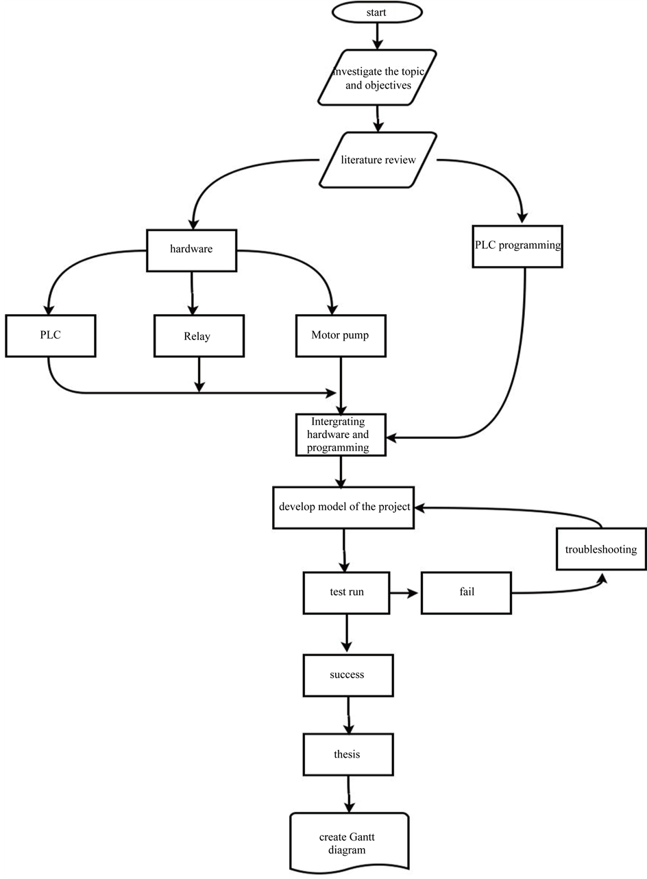
Figure 6. Flowchart of construction of model.
3.3. Construction of Model
Firstly, we need to connect our PLC to a computer using an adapter. Then we run the program (CX One programmer shown in Figure 7) and write the intended logic sequence for our experiment that is:
1) When switch is ON, turn the Timer A for 100 seconds.
2) During Timer A ON, the water pump motor is ON until Timer A is OFF.
3) When Timer A is OFF, turn ON Timer B (100 seconds).
4) When Timer B is OFF, switch ON the water pump motor and Timer C (100 seconds).
5) When Timer c is OFF, turn ON Timer D (100 seconds).
6) When Timer D is OFF, the counter resets the main switch and the cycle continue.
Next, we load the program that has been written into the PLC. After that, connect the push switch to the PLC by using connecting wire, the one we specified in our programming earlier. Then, connect the PLC External Output Terminal to the water pump motor (output). Now, we execute the logic program on the PLC. After the model has been completed, we do several test run for our model to make sure the PLC programming work as it intended. Any failure will be observed and documented so we will be able to do troubleshooting for our model. Figure 8 shows the model of construction software for irrigation control.
4. Result
4.1. Software Development PLC Programming
Programming instructions:

Figure 7. CX one programmer.

Figure 8. Construction software model for irrigation control.
1) When switch is ON, turn the Timer A for 1 hour.
2) During Timer A ON, the water pump motor is ON until Timer A is OFF.
3) When Timer A is OFF, turn ON Timer B (8 hours).
4) When Timer B is OFF, switch ON the water pump motor and Timer C (1 hour).
5) When Timer C is OFF, turn ON Timer D (14 hours).
6) When Timer D is OFF, the counter RESET the main switch and the cycle continue.
4.2. Hardware Development
Figure 9 shows an overview of work table in Farm Mechanization laboratory in Universiti Sultan Zainal Abidin campus. Figure 10 shows constructed model for irrigation control.
4.3. Simulation
Figure 11 shows an algorithm for automatic irrigation control.
5. Discussion
5.1. Introduction
Both hardware and software part are developed and built successfully. The system is complete when both of them are connected together. This chapter explains all the results related to both part.
5.2. Hardware
The microcontroller is connected directly to AC to DC adaptor that is functioning as power supply to switch on the control unit. The moisture sensor will start measuring and the data obtain will be sent to control unit in voltage form that will be processed by PIC microcontroller. Since the microcontroller has the capability of 10-bit

Figure 9. Overview of work table in Farm Mechanization Lab.
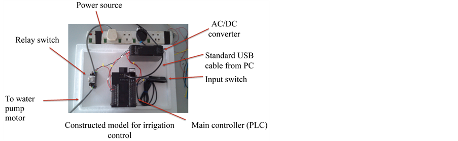
Figure 10. Constructed model for irrigation control.

Figure 11. Algorithm for automatic irrigation control.
analog to digital converter, it will convert and manipulate the data obtained to get the actual value of humidity. After that, these values are displayed on the LCD. The control unit also will instruct the pump to start working.
6. Conclusion
The project involved the design activity on both software and hardware development of PLC in agriculture mini hydroponic system. The design on circuitry system is involved for connecting between input and output system including push button device, microcontroller device, 240 volts power supply and water motor pump. The software development is created from basic concept on timer and counter application. By using this technique, this project was successful to automate basic irrigation system for hydroponic. The system will automatically circulate the fertilizer mix water throughout the system on selected period of morning and afternoon daily with less intervention of the user.
Cite this paper
Mohd Hudzari Razali,Syazili Roslan,Abdul Ssomad Mohd Abd Halim,Hayan Basit, (2016) Design and Development of Mechatronic Application in Agricultural Irrigation Device. World Journal of Engineering and Technology,04,450-459. doi: 10.4236/wjet.2016.43045
References
- 1. Selvaraj, K. (2010) Development of a “Programmable Logic Controller Circuitry” for Optimal Power Distribution in a Manufacturing Industries. Journal of Computer Science, 6, 250-252.
http://dx.doi.org/10.3844/jcssp.2010.250.252 - 2. (2005) Small Farm Mechanization Systems Development, Adoption and Utilization. Report, FFTC Annual Parts, Sri Lanka, 13-17.
- 3. Kamaruddin, R., Rukunuddin, I.H. and Seng, O.H. (2007) Research and Development of Agricultural Engineering in Malaysia. Paper, Country Asian, United Nations Centre, Pacific Engineering, Agricultural, 1-11.
- 4. Halim, M.Z.B. (2007) The Temperature Control System Using PLC.
- 5. Ismail, M.H. (2008) Rain Water PLC Based Detector and Valve Switcher.
- 6. Schumann, D., Fietsam, J., Rochel, E., Dixon, K., Imbayan, M. and Ibayan, M. (n.d.) Literature Review for the Design of a SCADA System.
- 7. Shah, C. (2004) Sensor Less Control of Stepper Motor Using Kalman Filter. Department of Electrical and Computer Engineering, Cleveland State University, Master of Science in Electrical Engineering.
NOTES

*Corresponding author.