Optics and Photonics Journal, 2011, 1, 167-171
doi:10.4236/opj.2011.14027 Published Online December 2011 (http://www.SciRP.org/journal/opj)
Copyright © 2011 SciRes. OPJ
Semiconductor Optical Amplifier (SOA)-Fiber Ring Laser
and Its Application to Stress Sensing
Yoshitaka Takahashi1, Shinji Sekiya2, Tatsuro Suemune3
1Department of Electronic Engineering, Graduate School of Engineering, Gunma University, Kiryu, Japan
2Package Mate rial Product i o n Di v i sion, Hitachi Cable, Ltd., Hitachi, Japan
3Personal Solutions Business Unit, NEC Corp., Kawasaki, Japan
E-mail: taka@el.gunma-u.ac.jp
Received October 11, 2011; revised November 10, 2011; accepted November 25, 201 1
Abstract
We have developed a novel optical fiber ring laser using a semiconductor optical amplifier (SOA) as the gain
medium, and taking advantage of polarization anisotropy of its gain. The frequency difference of the
bi-directional laser is controlled by birefringence which is introduced in the ring laser cavity. The beat fre-
quency generated by combining two counter-propagating oscillations is proportional to the birefringence, the
fiber ring laser of the present study is, therefore, applicable to the fiber sensor. The sensing signal is obtained
in a frequency domain with the material which causes the retardation change by a physical phenomenon to
be measured. For the application to stress sensing, the present laser was investigated with a photoelastic ma-
terial.
Keywords: Fiber Laser, Fiber Sensor, Ring Laser, Semiconductor Optical Amplifier, Optical Sensor
1. Introduction
Optical fiber sensors are widely used in various uses
since it has many advantages. Most of them detect an
optical intensity change as a sensing signal caused by
change in polarization, phase, loss, and fluorescence. In
such kinds of sensors, however, fluctuation of the source
intensity and/or a propagation loss will cause a meas-
urement error. Sensors which are not influenced by the
fluctuation have been required and studied, e.g. optical
heterodyne, a frequency-domain sensor, and so on. For
the application to a frequency-domain sensor, the authors
have studied a novel optical fiber ring laser [1-3].
In general cases birefringence applied to a ring laser is
reciprocal effect and no phase difference generates be-
tween two counter-propagating lights. Fiber ring lasers
for frequency-domain sensors were proposed, e.g., an
optical fiber gyro [4,5] using Sagnac effect and an opti-
cal current sensor [6,7] using Faraday effect. These ef-
fects are non-reciprocal effect.
But in the present study reciprocal effect, i.e., bire-
fringence was used, and making good use of the gain
anisotropy of SOA the authors developed the SOA-fiber
ring laser in which the phase difference occurred by in-
troducing a birefringent medium in the ring cavity be-
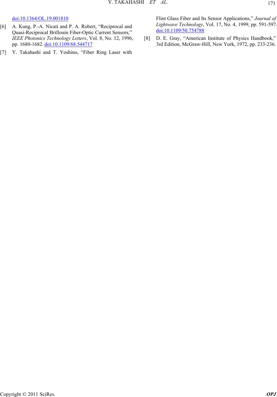
tween two counter-propagating oscillations. To investi-
gate the performance of the present laser, we introduced
a photoelastic material in the ring laser cavity and con-
firmed the frequency difference of the counter-propaga-
ting oscillations changed by applying stress to the mate-
rial proportionally.
2. Principle of Operation
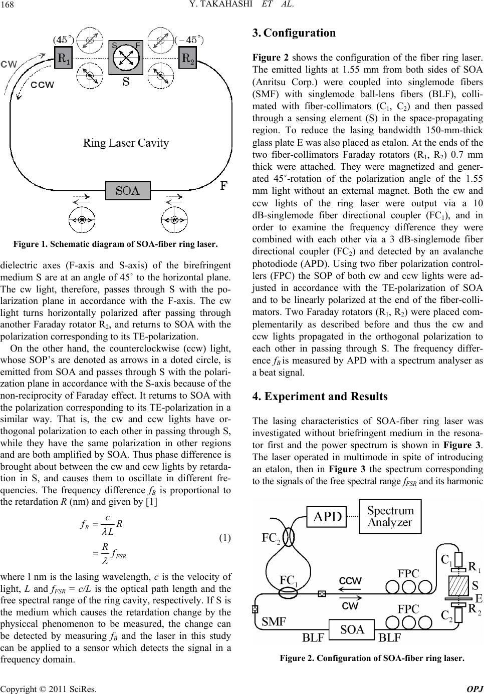
The operating principle of the SOA ring laser [1] is
shown in Figure 1. SOA is the gain medium of the laser.
It has polarization anisotropy of its gain and is regarded
as an amplifier only for TE-polarization, which is as-
sumed to be in accordance with the horizontal plane. The
ring cavity contains Faraday rotators R1 and R2 which
generate +45˚ and –45˚-rotation of the state of polariza-
tion (SOP) of light propagating in the clockwise (cw)
direction. The cavity also contains a medium S which
has birefringence (retardation R) and works as a sensing
element when the laser is applied to a fiber sensor.
First, consider light which propagates in the cw direc-
tion in the ring cavity. Horizontally polarized light emit-
ted from SOA is coupled into the cavity and passes
through R1, and, as a result, SOP of the cw light rotates
45˚ (an arrow in a solid circle shown in Figure 1). The
Y. TAKAHASHI ET AL.
168
Figure 1. Schematic diagram of SOA-fiber ring laser.
dielectric axes (F-axis and S-axis) of the birefringent
medium S are at an angle of 45˚ to the horizontal plane.
The cw light, therefore, passes through S with the po-
larization plane in accordance with the F-axis. The cw
light turns horizontally polarized after passing through
another Faraday rotator R2, and returns to SOA with the
polarization corresponding to its TE-polarization.
On the other hand, the counterclockwise (ccw) light,
whose SOP’s are denoted as arrows in a doted circle, is
emitted from SOA and passes through S with the polari-
zation plane in accordance with the S-axis because of the
non-reciprocity of Faraday effect. It returns to SOA with
the polarization corresp onding to its TE-polarization in a
similar way. That is, the cw and ccw lights have or-
thogonal polarization to each other in passing through S,
while they have the same polarization in other regions
and are both amplified by SOA. Thus phase difference is
brought about between the cw and ccw lights by retarda-
tion in S, and causes them to oscillate in different fre-
quencies. The frequency difference fB is proportional to
the retardation R (nm) and given by [1]
B
F
SR
c
f
R
L
R
f
  
(1)
where l nm is the lasing wavelength, c is the velocity of
light, L and fFSR = c/L is the optical path length and the
free spectral range of the ring cavity, respectively. If S is
the medium which causes the retardation change by the
physiccal phenomenon to be measured, the change can
be detected by measuring fB and the laser in this study
can be applied to a sensor which detects the signal in a
frequency domain.
3. Configuration
Figure 2 shows the configuration of the fiber ring laser.
The emitted lights at 1.55 mm from both sides of SOA
(Anritsu Corp.) were coupled into singlemode fibers
(SMF) with singlemode ball-lens fibers (BLF), colli-
mated with fiber-collimators (C1, C2) and then passed
through a sensing element (S) in the space-propagating
region. To reduce the lasing bandwidth 150-mm-thick
glass plate E was also placed as etalon. At the ends of the
two fiber-collimators Faraday rotators (R1, R2) 0.7 mm
thick were attached. They were magnetized and gener-
ated 45˚-rotation of the polarization angle of the 1.55
mm light without an external magnet. Both the cw and
ccw lights of the ring laser were output via a 10
dB-singlemode fiber directional coupler (FC1), and in
order to examine the frequency difference they were
combined with each other via a 3 dB-singlemode fiber
directional coupler (FC2) and detected by an avalanche
photodiode (APD). Using two fiber polarization control-
lers (FPC) the SOP of both cw and ccw lights were ad-
justed in accordance with the TE-polarization of SOA
and to be linearly polarized at the end of the fiber-colli-
mators. Two Faraday rotators (R1, R2) were placed com-
plementarily as described before and thus the cw and
ccw lights propagated in the orthogonal polarization to
each other in passing through S. The frequency differ-
ence fB is measured by APD with a spectrum analyser as
a beat signal.
4. Experiment and Results
The lasing characteristics of SOA-fiber ring laser was
investigated without briefringent medium in the resona-
tor first and the power spectrum is shown in Figure 3.
The laser operated in multimode in spite of introducing
an etalon, then in Figure 3 the spectrum corresponding
to the signals of the free sp ec tr al rang e fFSR and its harmonic
Figure 2. Configuration of SOA-fiber ring laser.
Copyright © 2011 SciRes. OPJ
169
Y. TAKAHASHI ET AL.
are shown. The center of the lasing wavelength was
1.562 mm. The optical path length of the ring cavity L
was 16.1 m and the calculated value of fFSR = c/L is 18.6
MHz, which corresponds to the one shown in Figure 3.
Various wave plates were inserted in the laser cavity
instead of a sensing element as known birefringent media
to change the frequency difference fB and the result is
shown in Figure 4. The dashed line is calculated value
with Equation (1) and the observed power spectrum at R
of 387.5 nm is also shown in Figure 4 with a quar-
ter-wave plate of 1550 nm. The result shows that retarda
tion can be determined by measuring the shift of fB and
the present fiber ring laser would be a sensor of birefrin-
gence in a frequency domain.
Figure 3. Power spectrum of SOA-fiber ring laser without
birefringent media.
Figure 4. Change of frequ enc y di ffer ence fB with applied reta r-
dation. Inset power spectrum is the case of R = 387.5 nm.
In a ring laser when the phase difference between
counter-propagating lights is small, oscillating frequen-
cies of them do not differ because of lock-in phenome-
non. Then if the inserted birefringence is small, fB re-
mains zero. Even if it is non-zero, a sign of the birefrin-
gence is uncertain. To avoid these problems a bias ele-
ment is inserted in the space-propagating region in addi-
tion to a sensing element S. As the case of small bire-
fringence, a sheet of PET film for viewgraph was in-
serted. Figure 5 shows the signal of fFSR + fB with and
without PET film. The traces are shifted up and down to
make the difference clear. The retardation was calculated
as 17.2 nm from the frequency shift 0.20 MHz, which
means the laser can measure such a small birefringence
with a bias element.
As the experiment for the application to stress sensing
a fused silica substrate was used as photoelastic crystal.
It is 5 × 10 × 10 mm3 and the applied stress was moni-
tored an attached strain gauge. It was inserted in the
space-propagating region as well as a quarter-wave plate.
The collimated beam passes through the 10 × 10 mm2
square plane and the stress was applied by a vise in the
direction perpendicular to the beam. The dependence of
the beat frequency shift on the pressure is shown in Fig-
ure 6. The dotted line denotes calculated value from
Brewster coefficient of fused silica at 633 nm [8] as ref-
erence. The beat frequency shift changes with the pres-
sure proportionally and closely to the dotted line. Since
dispersion of Brewster coefficient supposes to be small
the present ring laser can be applied to a fiber stress sen-
sor in a frequen c y domain.
Figure 5. Power spectrum of fFSR + fB signal. The upper and
the lower traces show without and with PET film.
Copyright © 2011 SciRes. OPJ
Y. TAKAHASHI ET AL.
170
Figure 6. Beat freque ncy difference on applied pr e ssure on
fused silica.
5. Discussion
In Figure 6 there are fluctuations and the accuracy is
degraded, which must be the problem in developing a
practical sensor. These might be caused by errors of a
sensing element and instability of the laser oscillation.
a) Errors of a sensing element
The applied stress might cause nonuniform strain in
the crystal. And it was difficult to attach a strain gauge
on the fused silica and the adhesion might be imperfect,
which causes errors of the measured pressure.
b) Instability of the laser oscillation
The polarization of the propagating light is not con-
stant because singlemode fibers were incorporated into
the ring laser cavity, and it is probable to cause the insta-
bility. In addition the difference between the designed
wavelength (1.55 mm) and the lasing wavelength, which
centered at 1.562 mm, will affect the oscillation. It
causes errors of both the polarization and the phase dif-
ference. The former reduces the SOA gain and the latter
induces errors of the retardation. Assuming circular bire-
fringence of a Faraday rotator and linear birefringence of
a sensing element has no dispersion, the rotation angle
and the retardation changes in proportion to the ratio of
the wavelengths. With this assumption the retardation
error was calculated and the result is plotted in Figure 7.
From Figure 7 the difference of the wavelength does not
seem to affect the oscillation significantly.
Figure 7. Retardation errors dependence on wavelength devia-
tion.
6. Conclusions
The SOA-fiber ring laser has been developed and as
the application to stress sen sing by introducing a pho toe-
lastic material in the cavity the beat frequency changed
as applying pressure proportionally. In the present laser
phase difference is generated by birefringence which is
reciprocal effect in the ring cavity. Since birefringence is
induced by many phenomena such as electromagnetic
field, pressure, and temperature, etc., sensors utilizing
the present fiber ring lasers are expecting to detect such
physical quantity in a frequency domain.
As described in the previous section, because of using
singlemode fiber the polarization of the propag ating light
might vary and should be stabilized. Using polariza-
tion-maintaining fiber instead of singlemode fiber the
authors have studied the stabilization of the fiber ring
laser. The improvement would make the practical fiber
sensor.
7. References
[1] Y. Takahashi, S. Sekiya and N. Iwai, “Semiconductor
Optical Amplifier(SOA)-Fiber Ring Laser for Sensor
Application,” Optical Review, Vol. 10, No. 4, 2003, pp.
315-317. doi:10.1007/s10043-003-0315-1
[2] Y. Takahashi, H. Kuroda and T. Suemune, “Semicon-
ductor Optical Amplifier-Fiber Laser and Its Application
for Temperature Sensing,” The Review of Laser Engi-
neering, Vol. 33, No. 5, 2005, pp. 329-332.
[3] T. Suemune and Y. Takahashi, “SOA-fiber ring laser and
its application to electric field sensing in frequency do-
main,” Optics and Lasers in Engineering, Vol. 45, No. 7,
2007, pp. 789-794. doi:10.1016/j.optlaseng.2006.12.002
[4] R. K. Kadiwar and I. P. Giles, “Optical Fibre Brillouin
Ring Laser Gyroscope,” Electronics Letters, Vol. 25, No.
25, 1989, pp. 1729-1731. doi:10.1049/el:19891157
[5] S. K. Kim, H. K. Kim and B. Y. Kim, “Er3+-Doped Fiber
Ring L aser for Gy roscope Applications,” Optical Letters,
Vol. 19, No. 22, 1994, pp. 1810-1812.
Copyright © 2011 SciRes. OPJ
Y. TAKAHASHI ET AL.
Copyright © 2011 SciRes. OPJ
171
doi:10.1364/OL.19.001810
[6] A. Kung, P.-A. Nicati and P. A. Robert, “Reciprocal and
Quasi-Reciprocal Brillouin Fiber-Optic Current Sensors,”
IEEE Photonics Technology Letters, Vol. 8, No. 12, 1996,
pp. 1680-1682. doi:10.1109/68.544717
[7] Y. Takahashi and T. Yoshino, “Fiber Ring Laser with
Flint Glass Fiber and Its Sensor Applications,” Journal of
Lightwave Technology, Vol. 17, No. 4, 1999, pp. 591-597.
doi:10.1109/50.754788
[8] D. E. Gray, “American Institute of Physics Handbook,”
3rd Edition, McGraw-Hill, New York, 1972, pp. 233-236.