 Optics and Photonics Journal, 2011, 1, 189-196 doi:10.4236/opj.2011.14030 Published Online December 2011 (http://www.SciRP.org/journal/opj) Copyright © 2011 SciRes. OPJ The Design and Experiment Studies of Optical Adapter with Integrated Dust Protection and Shutter Design Samuel I-En Lin Department of Power Mechanical Engineering National Formosa University, Chinese Taipei E-mail: samlin7@ms41.hinet.net Received August 10, 2011; revised September 9, 2011; accepted September 21, 2011 Abstract High power lasers (> +21dBm) have gradually become the common solution for signal transmitting systems including regional cable television, Fiber To The Home (FTTH), and gigabit passive optical networks (G- PONs) due to their ability to generate signals that can be transmitted over long distances. However, if protec- tive design is not implemented in the facility at the client side, users may be exposed to health hazards such as eye damage from these high-power lasers. High-power optical adapters with laser shutter use metal masks to prevent eye exposure to direct laser beams. They have progressively replaced conventional optical adapt- ers and entered the market mainstream. Our study uses the Elastic-Plastic theory together with parametric design to investigate the effect of geometry on the initial spring-back angle of a laser shutter. Once the force stabilizes, the angles of the initial spring back are found to be the same as the simulated results for several attempts. In our study, it is observed that factors including the thickness of the metal masking plate, the ini- tial design angle, the stiffness of the material and the boundary conditions have significant influence on the spring back angle. These can be used as references in design control. Keywords: High Power Leaser, Elastic-Plastic Theory, Laser Shutter, Optical Adapter 1. Introduction In 1966, researchers Kao and Hockham [1] proposed the theory of fiber optics and presented its potential applica- tion. Over time, the quality of optical communication improved extensively, and the bandwidth for communi- cation increased considerably. To date, fiber optics has become an essential medium of communication. High power light sources (> +21dBm) are used in transmitting data in fiber optic networks, and are additionally used in cable television. The common wavelengths used in to- day’s high power telecom lasers (1310 nm, 1550 nm, etc.) fall in the infrared, outside the visible portion of the spectrum. When these high power laser beams are emit- ted from the fiber optical terminal, human eyes are there- fore unable to recognize the hazard [2-4]. It is therefore required to install protective terminal units (for example, laser shutter) to prevent accidental ocular exposure to the high power laser beams. Integrated laser shutter have many benefits [5], as their geometric structure is fully compatible with IEC/TIA specifications, and their phy- sical dimensions can be fully compatible with any front panel board on the market. In addition to their suitability for automated production, their cost is very low. Metal plates have the ability to return to their original position when bent within the region of elastic deformation. The functionality of integrated laser shutter relies on this property. Figure 1 illustrates the sample application of an integrated laser shutter on an SC-type adaptor. The same structure can be applied in various optical commu- nication modules. Functions for preventing dust can also be included [6]. To ensure the unit can withstand repeated blocking and unblocking, the design analysis and stress analysis of the metal masking plates are very important factors. After a period of operation time, if a plate malfunctions and is unable to be restored to the design angle, laser beams may leak out and present a hazard, and dust could also enter the laser module which in turn reduces the laser life time. Tekaslan [7] studied the material property of stamped stainless steels, investigating the effects of different plate thicknesses and horizontal angles on the spring back an- gles. They found that a greater plate thickness and a lar- ger horizontal angle produce a larger spring back angle. Chang and Hsu [8] stamped and deformed stainless steel plates with a thickness of 0.1 mm (JIS SUS 301). When  S. I-En LIN 190 Figure 1. Typical dust proof lase r shutter on SC type adapter and its masking operation. (a) Sectional diagram of the adapter. (b) When turned on, the laser shutter blocks the laser beams, and also makes it difficult for dust to enter. (c) Optical connec- tor inserted in the adaptor, forming a light path. the load is removed, the residual stress in the plates causes the spring-back effect. Based on the actual proc- essing parameters during manufacturing, Chang and Hsu used finite element analysis to obtain optimal parametric combinations. Different stamping speed, angle of stamp- ing pressure head and the radius of the round angle at the front end of the pressure head were considered. The Ta- guchi method was used in the analysis to produce a three factor/three level combination. Lastly, the stamping of a single channel V-shaped plate was simulated. In the end, a set of optimal parametric combinations was obtained. Chen [9] used a finite element calculation simulate the effects of various parameters on the formation of the plates, including the material properties of the SMT plates, the bending radius of the molding unit, the thick- ness of the plates, and the length of the lever arm. The force on each plate was analyzed using CAD and CAE. The simulation results were used with the Taguchi method to obtain the optimal combination with minimal force. In this study, the actual material properties obtained from the stretch experiment are used in the finite element analysis software MSC/Marc. Simulation analysis on the structure and packaging parameters of the photo inter- rupter unit is performed. Trial and error time is reduced and hence an improved design is achieved. The initial angle, bending radius, thickness, gap distance, and the stiffness of the material for the dust-proof laser shutter are evaluated and their effects on the spring back angle are studied. Through experiment, it is found that the Elastic-Plastic design theory is feasible to be used in our application. Lastly, the Taguchi method is used on ex- perimental data and the signal to noise ratio (S/N) of each influencing factor is analyzed. The effects of each factor on the spring-back value of the laser shutter are investigated. 2. Elastic-Plastic Theory Metal materials show elastic behavior and plastic behav- ior. When receiving an external load, the relation- ship between the initial stress and the strain is linearly elastic. Material parameters include Young's modulus of elastic- ity and Poisson’s ratio. After the resistance of materials reaches a certain value, materials show irreversible plas- tic deformation. The relationship between stress and strain becomes non-linear. The relationship diagrams on engineering stress and strain obtained from the stretch test must be converted to relationship diagrams on true stress and strain, as illustrated below. The engineering stress (σtrue) and strain (εture) are expressed as 0 00 ,nom nom ll l (1) where F, A0, l and l0 are force, un-deformed area, deformed length and un-deformed length respectively. For elastic-plastic theory, we employ true stress and strain: Copyright © 2011 SciRes. OPJ  S. I-En LIN 191 1, 1true nomnomtruenomln (2) For material configuration in MSC/Marc, if the data from the stretch test is directly entered for the material property, this method is known as the direct input of experimental data. In our study, the test data points en- tered are different. The engineering stress and engineer- ing strain obtained from stretch test are converted to true stress (σtrue) and true strain (εture) within the plastic range (Equation 2). In addition to entering the relationship between true stress and true strain, the elastic-plastic theory can determine the power law elastic-plastic behavior. The relationship is expressed as: m true true K (3) where K is the true stress when the true strain is equal to 1-also known as the strength constant-and m is the stiff- ness index. Take the log of the equation to obtain the values for K and m using the least squares method. For multiple groups of data, the average value may be taken to obtain an average strength constant and average strain stiffness index. Due to the fact that MSC/Marc requires the input parameters to be the true stress and true strain within the plastic region, equation in [10] is used: –tp true Y (4) We rearrange (3) to: Y ln K m tp tp Ae (5) The yield strength σY, strength constant K, stiffness index m, and power law model parameters A and B can all be obtained from experiment [11]. In MSC/Marc, we can configure two independent material variables (true strains within the temperature range and plastic range). The total stress obtained from the experiment is re- presented by two independent functions. During the si- mulation, to study the effects of temperature change on displacement, it is easier to directly input experimental data. If temperature factors are not considered, the diffe- rence between using the power law model or directly using experimental data is unnoticeable. In our study, the mate- rial properties are based on data obtained directly from the experiment. 3. Simulation Model and Experiment Setup The simulation built for this investigation is mainly used to study the effects of different parameters on the dis- placement of the laser shutter. The interactions between these controlling parameters are not included in the scope of this study. 3.1. Model Construction and Limitations Numerous design limitations exist for the integrated laser shutter since the original adapter modules must comply with regulations including IEC/TIA. The laser shutter component is only an accessory whose function is to block laser beams from leaking when the adapter is being unplugged. To achieve an accurate simulation the models are rendered in 3D. The optical fiber connector is con- sidered as a rigid body. When plugging in the connector, it presses onto the laser shutter component. When un- plugging the connector, the laser shutter component re- turns to certain angle (known as the spring-back angle) to block the laser beams in time (Figure 2). The spring back angle (θ) must be large enough to be able to block the laser beams completely and to fully seal to prevent dust from entering. The spring-back angle is therefore a very important figure in the design. Quasi-static analysis is used in our study. The degrees of freedom for the boundary conditions for the bottom part of the laser shutter component are fixed (Figure 2). We make the following basic assumptions in the simulation: a) It is a quasi-static process. The movement of the adapter is slow and we ignore the effects of strain rate. The fiber optical adapter and fiber optical con- nectors are totally rigid bodies. b) The masking plates are made of homogenous and isotropic materials which obey the yield criteria of von Mises. Materials with lattices oriented in the same direction are used in the simulation as well as real sample production. Figure 2. Simulated laser shutter. The optical connector and adaptor are treated as rigid bodies. The optical con- nector moves to the right and presses on the laser shutter, then returns to the initial position. This is to measure the spring-back angle. T is the thickness of the shutter plate and D is the control space of shutter base-plate. Copyright © 2011 SciRes. OPJ  S. I-En LIN 192 c) An isotropic hardening mode is used in strain stiff- ness. Gravity effects between the material and the modules are ignored. Temperature effects during processing are also ignored. The separating force is set to be 0.01. The contact friction between the fiber optical connector and the masking plates is ignored. 3.2. Uni-Axial Test for Plates and Test Verification An uni-axial test was performed using an HT-9711 dou- ble axis test machine. During the stretch test, two types of plates (denoted Hv A and Hv B, where Hv B > Hv A) were used. The number of specimens used is sufficient to confirm test repeatability and to minimize experimental error. The temperature of the plates is controlled to be at room temperature (25˚C). Once at room temperature, the plates are stretched at a stretching speed of 0.2 mm/sec until they break off. The relationship between engineer- ing stress and engineering strain obtained from the expe- riment is shown in Figure 3. The yield strength obtained using the intercept method is 0.2%. In other words, on the strain axis, at the location of 0.002, we draw a line on the engineering stress curve parallel to the elastic curve. The first few sets of data are extracted. The stress and strain are converted using (Equation 2) to obtain the true stress and true strain, as shown in Figure 4. After calcu- lation, the material parameters obtained from the ex- periment are listed in Table 1. In the sample verification test, we used a stepper mo- tor to drive the fiber optical connector. Plugging and unplugging verification tests are performed with a speed of 10 mm/sec. The initial geometry of the sample under test is configured to be ψ = 120 degrees, T = 0.08 mm, R = 0.5 mm, and Hv B. We have a total of three samples. Figure 3. Engineering stress and strain diagram for stretch- ing material plates. Figure 4. True stress and strain diagram for stretching ma- terial plates after converting from engineering stress and strain. Table 1. Parameters for material simulation. Parameters values Vicker’s hardness Hv A Hv B Young’s Modulus 47.4 × 10⁹ N/m2 54.8 × 10⁹ N/m2 Possion’s ratio 0.3 0.3 Yield stress 286 × 106 N/m2 340 × 106 N/m2 The spring-back angles are recorded after every 100 plugging and unplugging maneuvers, for a total repe- tition of more than 6000 times. In the experiment, stable results are shown after approximately 25 plugging and unplugging maneuvers. To simplify the presentation of data, we only show results up to 2000 repetitions. 4. Results and Discussion 4.1. The effects of Design Geometry on the Spring-Back Angles In our study, we used finite element analysis software MSC/Marc to simulate the effects of parameter changes on the laser shutter plate. These design parameters in- clude: 1) the bending radius at the bottom of the plate 2) the initial opening angle 3) the thickness of the plate and 4) the boundary conditions of the bottom part, for exam- ple, with or without gaps. Figure 5 illustrates the effects of the bending radius on the spring-back value. From the simulation, it can be observed that a larger bending ra- dius causes a positive increase in the spring- back angle, in accordance with common sense. Copyright © 2011 SciRes. OPJ  S. I-En LIN 193 Figure 5. The effects of bending radius at the bottom of the laser shutter on the spring-back angle. The effects of initial opening angles (ψ) for two mater- ials with different hardness on the spring-back angle are illustrated in Figure 6. In the figure, it can be observed that, for the same materials with different stiffnesses, the initial opening angle does affect the spring-back angle. In addition, compared to materials with lower stiffness (Hv A), materials with higher stiffness (Hv B) have greater effects on the spring-back angle. For fixed geometric and material parameters, the effects of these two thicknesses on the spring-back angles are analyzed, as shown in Figure 7. A thinner thickness has better effects on the spring-back angles of the masking plate. This completely agrees with the real life experience for common spring- back analysis. The fixture method for the base of the laser shutter component does affect the manufactur- ing assembly method. If we aim to have total enclosure, every component must be sealed together without gaps. This would introduce difficulties during the packaging process. Greater gaps ease the automation process during manufacturing, but we must consider the effects on the spring-back angles. Analyzed results in Figure 8 illus- trate that under ideal conditions where all components are fixed (Type-I), the spring-back angle is at its opti- mum. In Type-II, packaging gaps exist at the base. Greater gaps produce smaller spring-back angles. During the design process, it is required to have a solution where both concerns are considered. 4.2. Effects of Changes in Material Property on the Spring-Back Angles Properties like material ductility often depend on processing temperature; this in turn affects the spring- back value. In our study, two materials with different stiffness are used for comparison, where Hv B has 32% higher stiffness than Hv A, and more yield stress, as Figure 6. The effects of the initial angle of the laser shutter on the spring-back angle. Figure 7. The effects of the thickness the laser shutter on the spring-back angle. Figure 8. The effects of boundary conditions on the spring- back angle. Copyright © 2011 SciRes. OPJ  S. I-En LIN 194 obtained from the data from the stretching test. In Figure 9, we have compared materials with the same geometric conditions but with different stiffness. Due to the fact that the material of which Hv B is composed demon- strates better resistance to deformation, analyzed results show that it has a greater spring-back angle. However, it is not suitable to only aim for higher stiffness, as the lat- tice could break if the stress is concentrated at the bend- ing area, and in turn cause the entire masking purpose to malfunction. It is necessary to perform experiments (re- peated plugging and unplugging) to verify its operational life time. Through analysis, it can be observed that Hv B shows better results than Hv A, and therefore only Hv B materials are used for the repeated plugging and unplug- ging experiment (Figure 10). Under the condition where T=0.08mm, after stabilization, the spring-back angles are measured. Data from simulation agrees with the data obtained from the experiment. This confirms that the elastic-plastic theory can be applied in the design of laser shutter components. Figure 9. The effects of material stiffness on the spring- back angle. Figure 10. Comparing spring-back angle from experiment and simulation for sample Hv B. 4.3. Taguchi method The Taguchi analysis method is used in order to optimize the design. We first analyze the properties of important parameters to determine the number of factors and levels, and also to judge if interaction effects exist. We then select the suitable orthogonal arrays to perform factor allocation which are later to be used as a baseline for system design and execution. In the process of paramet- ric design, the main aim is to determine the optimum combination for factors and levels. This is based on the value of S/N. Among all combinations, there is always one with the largest S/N value; this combination simul- taneously optimizes all factors. Through analysis, it can be seen that if we control the behavior of a factor at a certain level within a particular region, a larger S/N value means a smaller degree of variation in quality, and we will then be one step closer to the ideal goal. Based on the analyzed results mentioned above, we determine the important factors to be (1) the bending radius at the base of the plate (2) the initial opening angle and (3) the thickness of the plate. Levels for each factor are listed in Table 2. The corresponding orthogonal ta- bles L9(33) are constructed as illustrated in Table 3. In this table, each factor/level combination appears three times. This method is very direct and very eco- nomical. Experiments involving many factors can be carried outsimultaneously. Using the repeatability of the experiment, each influential factor in the orthogonal ta- ble can be examined to determine an effective design while limiting the number of experiments. Based on the parameter values for the factors, the maximum average S/N ratio for each factor level is de- termined. For materials with stiffness Hv A and Hv B, we analyze their S/N ratio separately. For Hv A, Figure 11 shows the factor diagram for the “larger the better” (LTB) characteristic. In Table 2, the combination for the level of the optimal LTB factor is A2 = 0.4, B1 = 100, C2 = Type-I 0.08. The orthogonal table in Table 3 L9(33) shows the optimal combination is the fourth group, and it also has a better value for spring-back angle. For Hv B, Table 2. Taguchi controlling factor levels. Geometric ParametersR ψ B Factors A B C Level 1 0.3 100 Type-i Level 2 0.4 120 Type-ii 0.08 Level 3 0.5 140 Type-ii 0.1 Copyright © 2011 SciRes. OPJ  S. I-En LIN 195 Table 3. Taguchi orthogonal table and simulated results. R ψ B Hv A angles Hv B angles 1 1 1 1 53.53 75.47 2 1 2 2 52.19 80.82 3 1 3 3 51.88 86.79 4 2 1 2 56.58 77.4 5 2 2 3 53.17 83.48 6 2 3 1 47.33 86.76 7 3 1 3 51.49 76.87 8 3 2 1 53.33 81.26 9 3 3 2 50.41 87.28 Figure 11. Taguchi LTB factor diagram for Hv A. Figure 12 shows the factor diagram for the LTB charac- teristic. In Table 2, the combination for the level of the optimal LTB factor is A2 = 0.4, B1 = 140, C3 = Type-I 0.1. These optimized combinations can be applied in real life according to the design characteristics. The value for k can be calculated as, K= S/Nmax – S/Nmin, where I is the variance of the factors in the ex- periment, that is, the difference between the maximum value and the minimum value of the S/N ratio. A larger K value means a larger variance, which shows that this factor has a greater influence. For Hv A, as shown in Fig.11, the K value for factor A is 0.09, the K value for factor B is 0.65 and the K value for factor C is 0.2. Since the K value for factor B (represents the initial angle of the plates) is larger, its variance is therefore the largest, which means the change in the spring-back angle is also the largest. Similarly, the stiffness of Hv B is also examined, as shown in Figure 12. The K value of factor B is again quite large, therefore the initial angle has very important Figure 12. Taguchi LTB factor diagram for Hv B. effects on the spring-back angle for both masking plates with different stiffness. 5. Conclusions High power lasers are commonly utilized in fiber optical networks. Their related masking products must comply with the existing telecommunication regulations and therefore the potential for drastic change is limited. It is very important that masking accessories be reliably de- signed and precisely manufactured. Our study targets the geometric structure of the laser shutter components. Us- ing the elastic-plastic theoretical model and experimental results, the relationships between the spring-back value and the geometric parameters have been investigated. The following conclusions are obtained: Using the elastic-plastic model to simulate the mask- ing structure for the laser shutter, the spring-back angle from the experiment is very close to that of simulated values (within 5 degrees). This confirms that this method can be applied to masking device design. From the simulation it can also be seen that, among the factors which have great influences, if the thick- ness of the plate is thin, the bending radius is large and the yield stress of the material is large, then the ability for springing-back is better. The effects of the initially configured angle ψ on the spring-back angle depend on the stiffness of the material. A small gap in the enclosure at the base of the mask- ing plate packaging helps the plate to spring back effectively after plugging and unplugging. With the same geometric design, higher stiffness causes greater spring-back angles. One must be care- ful that high stiffness may cause the lattice to break during manufacturing process, which could produce Copyright © 2011 SciRes. OPJ  S. I-En LIN Copyright © 2011 SciRes. OPJ 196 small gaps. Reliability tests are recommended for ve- rification purposes. 6. References [1] K. C. Kao and G. A. Hockham, “Dielectric-Fibre Surface Waveguides For Optical frequencies,” Proc, IEE, Vol. 133, No. 7, 1966, pp.1151-1158 [2] S. I. E. Lin, “Dust Cap for Fiber Optic Adapter,” US Patent No. 0310795, 2008. [3] S. I E. Lin, Fiber optic adapter with integrated shutter, US patent, 2009/0028507. [4] S. I. E. Lin, “Dust Shutter for Optical Adapter,” US Pat- ent No. 0101758, 2008. [5] “SANWA Electronic Co. Laser Shutter,” Japanese Patent No. 2008-225133 A, 25 September 2008. [6] Fitel Product catalog, MPO Adapter with Shutter Design, Furukawa Electronics, Japan, 2010. [7] Ö. Tekaslan, N. Gerger and U. Şeker, “Determination of Spring-Back of Stainless Steel Sheet Metal in ‘V’ Bend- ing Dies,” Materials and Design, Vol. 29, No. 5 ,2008, pp. 1043-1050. doi:10.1016/j.matdes.2007.04.004 [8] C. C. Chang and F. M. Hsu, “Effects of Punch Radius and Offset on the Spring Back of Micro Right Angle Bending,” Master dissertation, National Kaohsiung Uni- versity of Applied Sciences, Taiwan, 2007. [9] W. Y. Chiou and M. H. Chen, “The Optimal Design and Stress Analysis for SMT Spring Finger,” Master disserta- tion, National Kaohsiung University of Applied Sciences, Taiwan, 2010. [10] “MSC\Marc 2010 User Manual,” MSC Software Corpo- ration, USA, 2010. [11] Y. Ueda, K. Lida, M. Saito and A. Okamoto, “Finite Element Model and Residual Stress Calculation for Multi-Pass Welded Joint between a Sheet Metal and the penetrating Pipe,” Modeling of Casting, Welding and Advanced Solidification Processes-V, 1991, pp. 219-227. [12] W. K. Dai, “A Study on Stent Plastic Forming,” Master dissertation, National Sun Yat-sen University, Taiwan, 2004. [13] D. Fratila and C. Caizar, “Application of Taguchi Method to Selection of Optimal Lubrication and Cutting Condi- tions in Face Milling of AlMg3,” Journal of Cleaner Pro- duction, Vol. 19, No. 6-7, 2011, pp. 640-645. doi:10.1016/j.jclepro.2010.12.007 [14] F. O. Sonmez and A. Demir, “Analytical Relations between Hardness and Strain for Cold Formed Parts,” Journal of Materials Processing Technology, Vol. 186, No. 1- 3, 2007, pp. 163-173. doi:10.1016/j.jmatprotec.2006.12.031
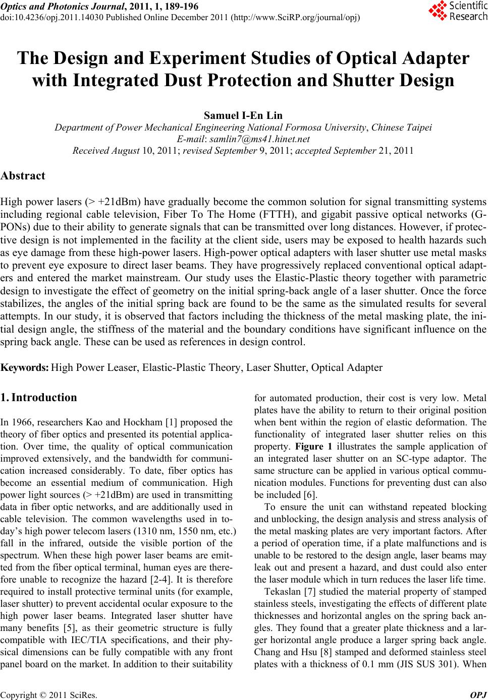
|