Paper Menu >>
Journal Menu >>
 Intelligent Information Management, 2009, 1, 89-97 doi:10.4236/iim.2009.12014 Published Online November 2009 (http://www.scirp.org/journal/iim) Copyright © 2009 SciRes IIM Optimization of Fused Deposition Modelling (FDM) Process Parameters Using Bacterial Foraging Technique Samir Kumar PANDA1, Saumyakant PADHEE2, Anoop Kumar SOOD3, S. S. MAHAPATRA4 1Department of Mechanical Engineering, National Institute of Technology, Rourkela, India 2Department of Manufacturing Science and Technology, Veer Surendra Sai University of Technology, Sambalpur, India 3Department of Manufacturing Science, National Institute of Foundry and Forge Technology, Ranchi, India 4Department of Mechanical Engineering, National Institute of Technology, Rourkela, India Email: {Samirpanda.nitrkl, soumyakantpadhee2011,anoopkumarsood}@gmail.com, mahapatras s2003@yahoo.com Abstract: Fused deposition modelling (FDM) is a fast growing rapid prototyping (RP) technology due to its ability to build functional parts having complex geometrical shapes in reasonable build time. The dimen- sional accuracy, surface roughness, mechanical strength and above all functionality of built parts are depend- ent on many process variables and their settings. In this study, five important process parameters such as layer thickness, orientation, raster angle, raster width and air gap have been considered to study their effects on three responses viz., tensile, flexural and impact strength of test specimen. Experiments have been con- ducted using central composite design (CCD) and empirical models relating each response and process pa- rameters have been developed. The models are validated using analysis of variance (ANOVA). Finally, bacte- rial foraging technique is used to suggest theoretical combination of parameter settings to achieve good strength simultaneously for all responses. Keywords: fused deposition modelling (FDM), strength, distortion, bacterial foraging, ANOVA, central composite design (CCD) 1. Introduction Reduction of product development cycle time is a major concern in industries to remain competitive in the mar- ketplace and hence, focus has shifted from traditional product development methodology to rapid fabrication techniques like rapid prototyping (RP) [1–5]. Although RP is an efficient technology, full scale application has not gained much attention because of compatibility of presently available materials with RP technologies [6,7]. To overcome this limitation, one approach may be de- velopment of new materials having superior characteris- tics than conventional materials and its compatibility with technology. Another convenient approach may be suita- bly adjusting the process parameters during fabrication stage so that properties may improve [8,9]. A critical review of literature suggests that properties of RP parts are function of various process related parameters and can be significantly improved with proper adjustment. Since mechanical properties are important for functional parts, it is absolutely essential to study influence of various process parameters on mechanical properties so that im- provement can be made through selection of best settings. The present study focus on assessment of mechanical properties viz. tensile, flexural and impact strength of part fabricated using fused deposition modelling (FDM) technology. Since the relation between a particular me- chanical property and process parameters related to it is difficult to establish, attempt has been made to derive the empirical model between the processing parameters and mechanical properties using response surface methodol- ogy (RSM). In addition, effect of each process parameter on mechanical property is analysed. Residual analysis has been carried out to establish validity of the model. De- velopment of valid models helps to search the landscape to find out best possible parametric combination resulting in theoretical maximum strength which has not been ex- plored during experimentation. In order to follow search procedure in an efficient manner, latest evolutionary technique such as bacteria foraging has been adopted due to its superior performance over other similar random search techniques [10]. First, bacteria foraging is easier to implement because only few parameters need to be ad-  S. K. PANDA ET AL. 90 justed. Every bacterium remembers its own previous best value as well as the neighbourhood best and hence, it has a more effective memory capability than other techniques. Bacteria foraging is more efficient in maintaining the diversity of the swarm as all the particles use the infor- mation related to the most successful particle in order to improve themselves. In contrast, the worse solutions are discarded and only the good ones are saved in genetic algorithm (GA) [11]. Therefore, the population revolves around a subset of the best individuals in GA. Particle swarm optimization (PSO) can be considered as a good option because of its fast convergence but it has the ten- dency to get trapped at local optimum unless some pro- cedure is adopted to escape [12]. 2. Literature Review Fused deposition modelling (FDM) is one of the RP processes that build part of any geometry by sequential deposition of material on a layer by layer basis. The process uses heated thermoplastic filaments which are extruded from the tip of nozzle in a prescribed manner in a semi molten state and solidify at chamber temperature. The properties of built parts depend on settings of vari- ous process parameters fixed at the time of fabrication. Recently, research interest has been devoted to study the effect of various process parameters on responses ex- pressed in terms of properties of built parts. Studies have concluded through design of experiment (DOE) ap- proach that process parameters like layer thickness, raster angle and air gap significantly influence the responses of FDM ABS prototype [13,14]. Lee et al. [15] performed experiments on cylindrical parts made from three RP processes such as FDM, 3D printer and nano-composite deposition (NCDS) to study the effect of build direction on the compressive strength. Out of three RP technolo- gies, parts built by NCDS are severely affected by the build direction. Wang et al. [16] have recommended that material used for part fabrication must have lower glass transition temperature and linear shrinkage rate because the extruded material is cooled from glass transition temperature to chamber temperature resulting in devel- opment of inner stresses responsible for appearance of inter- and intra-layer deformation in the form of cracking, de-lamination or even part fabrication failure. Belle- humeur et al. [17] have experimentally demonstrated that bond quality between adjacent filaments depends on en- velope temperature and variations in the convective con- ditions within the building part while testing flexural strength specimen. Temperature profiles reveal that tem- perature at bottom layers rises above the glass transition temperature and rapidly decreases in the direction of movement of extrusion head. Microphotographs indicate that diffusion phenomenon is more prominent for adjacent filaments in bottom layers as compared to upper layers. Simulation of FDM process using finite element analysis (FEA) shows that distortion of parts is mainly caused due to accumulation of residual stresses at the bottom surface of the part during fabrication [18]. The literature reveals that properties are sensitive to the processing parameters because parameters affect meso-structure and fibre-to- fibre bond strength. Also uneven heating and cooling cycles due to inherent nature of FDM build methodology results in stress accumulation in the built part resulting in distortion which is primarily responsible for week bond- ing and thus affect the strength. It is also noticed that good number of works in FDM strength modelling is devoted to study the effect of processing conditions on the part strength but no significant effort is made to de- velop the strength model in terms of FDM process pa- rameters for prediction purpose. The present study uses the second order response surface model to derive the required relationship among respective process parame- ters and tensile, flexural and impact strength. The predic- tive equations once validated can be used to envisage theoretical possible best parameter settings to attain maximum in response characteristic. Hence, the problem becomes constrained optimization problem. In this study, bacteria foraging approach has been adopted to deal with the optimization problem. The use of evolutionary algorithms to solve complex optimization problems is very common these days be- cause they provide very competitive results when solving engineering design problems [19,20]. Furthermore, swarm intelligence approaches have been also used to solve this kind of problems [21,22]. However, most of the work is centered on some algorithms such as Particle Swarm Optimization [23], Ant Colony Optimization [24] and Artificial Bee Colony [25]. Recently, another swarm- intelligence-based model known as Bacterial Foraging Optimization Algorithm (BFOA), inspired in the behav- ior of bacteria E. Coli in its search for food, has been proposed. Three behaviors were modeled by Passino in his original proposal [26]: 1) Chemotaxis, 2) reproduc- tion and 3) elimination-dispersal. BFOA has been suc- cessfully applied to solve different type of problems like forecasting [27], transmission loss reduction [28] and identification of nonlinear dynamic systems [29]. 3. Experimental Procedure The tensile test and three-point bending tests were per- formed using Instron 1195 series IX automated material testing system with crosshead speeds of 1mm/s and 2mm/s respectively in accordance with ISO R527:1966 and ISO R178:1975 respectively. Charpy impact test performed in Instron Wolpert pendulum impact test ma- chine is used to determine the impact strength of speci- men in accordance with ISO 179:1982. During impact testing, specimen is subjected to quick and intense blow by hammer pendulum striking the specimen with a speed of 3.8m/s. The impact energy absorbed is measure of the Copyright © 2009 SciRes IIM 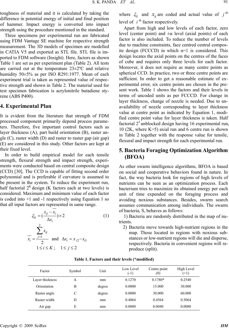 S. K. PANDA ET AL. Copyright © 2009 SciRes IIM 91 toughness of material and it is calculated by taking the difference in potential energy of initial and final position of hammer. Impact energy is converted into impact strength using the procedure mentioned in the standard. where ij and are coded and actual value of th level of th factor respectively. ij xj i Apart from high and low levels of each factor, zero level (center point) and ±α level (axial points) of each factor is also included. To reduce the number of levels due to machine constraints, face centred central compos- ite design (FCCCD) in which α=1 is considered. This design locates the axial points on the centres of the faces of cube and requires only three levels for each factor. Moreover, it does not require as many centre points as spherical CCD. In practice, two or three centre points are sufficient. In order to get a reasonable estimate of ex- perimental error, six centre points are chosen in the pre- sent work. Table 1 shows the factors and their levels in terms of uncoded units as per FCCCD. For change in layer thickness, change of nozzle is needed. Due to un- availability of nozzle corresponding to layer thickness value at centre point as indicated by Equation 1, modi- fied centre point value for layer thickness is taken. Half factorial 25 unblocked design having 16 experimental run, 10 (2K, where K=5) axial run and 6 centre run is shown in Table 2 together with the response value for tensile, flexural and impact strength for each experimental run. Three specimens per experimental run are fabricated using FDM Vantage SE machine for respective strength measurement. The 3D models of specimen are modelled in CATIA V5 and exported as STL file. STL file is im- ported to FDM software (Insight). Here, factors as shown Table 1 are set as per experiment plan (Table 2). All tests are carried out at the temperature 23±2ºC and relative humidity 50±5% as per ISO R291:1977. Mean of each experiment trial is taken as represented value of respec- tive strength and shown in Table 2. The material used for test specimen fabrication is acrylonitrile butadiene sty- rene (ABS P400). 4. Experimental Plan It is evident from the literature that strength of FDM processed component primarily depend process parame- ters. Therefore, five important control factors such as layer thickness (A), part build orientation (B), raster an- gle (C), raster width (D) and raster to raster gap (air gap) (E) are considered in this study. Other factors are kept at their fixed level. 5. Bacteria Foraging Optimization Algorithm (BFOA) In order to build empirical model for each tensile strength, flexural strength and impact strength, experi- ments were conducted based on central composite design (CCD) [30]. The CCD is capable of fitting second order polynomial and is preferable if curvature is assumed to be present in the system. To reduce the experiment run, half factorial 2K design (K factors each at two levels) is considered. Maximum and minimum value of each factor is coded into +1 and -1 respectively using Equation 1 so that all input factors are represented in same range. As other swarm intelligence algorithms, BFOA is based on social and cooperative behaviors found in nature. In fact, the way bacteria look for regions of high levels of nutrients can be seen as an optimization process. Each bacterium tries to maximize its obtained energy per each unit of time expended on the foraging process and avoiding noxious substances. Besides, swarm search assumes communication among individuals. The swarm of bacteria, S, behaves as follows: () ij i ij i xx x 2 (1) 1) Bacteria are randomly distributed in the map of nu- trients. 2 1 2 ij j i x x and 21ii 2) Bacteria move towards high-nutrient regions in the map. Those located in regions with noxious sub- stances or low-nutrient regions will die and disperse, respectively. Bacteria in convenient regions will re- produce (split). i x xx 1iK ; 12 j Table 1. Factors and their levels (*modified) Factor Symbol Unit Low Level (-1) Centre point (0) High Level (+1) Layer thickness A mm 0.1270 0.1780* 0.2540 Orientation B degree 0.0000 15.000 30.000 Raster angle C degree 0.0000 30.000 60.000 Raster width D mm 0.4064 0.4564 0.5064 Air gap E mm 0.0000 0.0040 0.0080 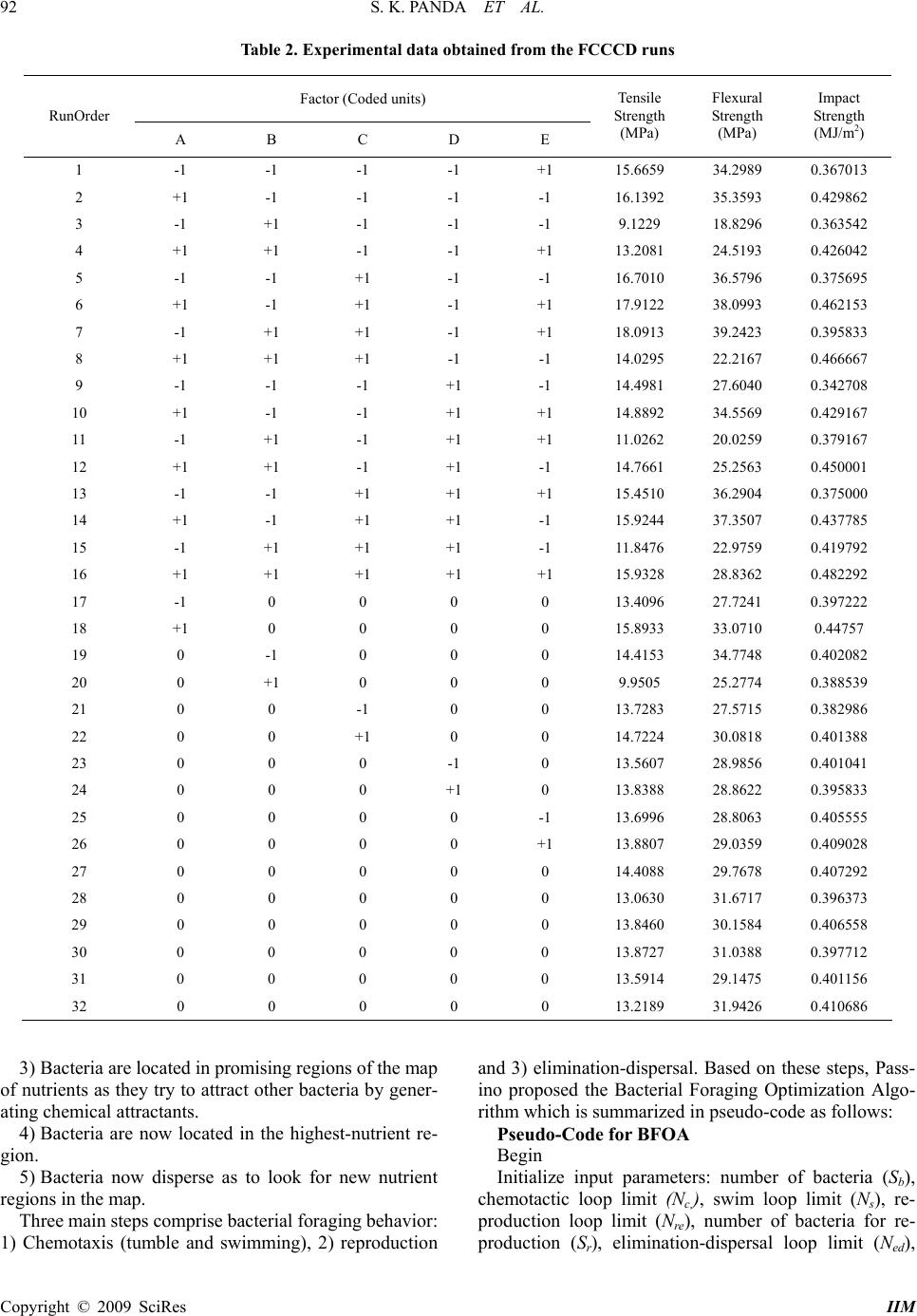 S. K. PANDA ET AL. 92 Table 2. Experimental data obtained from the FCCCD runs Factor (Coded units) RunOrder A B C D E Tensile Strength (MPa) Flexural Strength (MPa) Impact Strength (MJ/m2) 1 -1 -1 -1 -1 +1 15.6659 34.2989 0.367013 2 +1 -1 -1 -1 -1 16.1392 35.3593 0.429862 3 -1 +1 -1 -1 -1 9.1229 18.8296 0.363542 4 +1 +1 -1 -1 +1 13.2081 24.5193 0.426042 5 -1 -1 +1 -1 -1 16.7010 36.5796 0.375695 6 +1 -1 +1 -1 +1 17.9122 38.0993 0.462153 7 -1 +1 +1 -1 +1 18.0913 39.2423 0.395833 8 +1 +1 +1 -1 -1 14.0295 22.2167 0.466667 9 -1 -1 -1 +1 -1 14.4981 27.6040 0.342708 10 +1 -1 -1 +1 +1 14.8892 34.5569 0.429167 11 -1 +1 -1 +1 +1 11.0262 20.0259 0.379167 12 +1 +1 -1 +1 -1 14.7661 25.2563 0.450001 13 -1 -1 +1 +1 +1 15.4510 36.2904 0.375000 14 +1 -1 +1 +1 -1 15.9244 37.3507 0.437785 15 -1 +1 +1 +1 -1 11.8476 22.9759 0.419792 16 +1 +1 +1 +1 +1 15.9328 28.8362 0.482292 17 -1 0 0 0 0 13.4096 27.7241 0.397222 18 +1 0 0 0 0 15.8933 33.0710 0.44757 19 0 -1 0 0 0 14.4153 34.7748 0.402082 20 0 +1 0 0 0 9.9505 25.2774 0.388539 21 0 0 -1 0 0 13.7283 27.5715 0.382986 22 0 0 +1 0 0 14.7224 30.0818 0.401388 23 0 0 0 -1 0 13.5607 28.9856 0.401041 24 0 0 0 +1 0 13.8388 28.8622 0.395833 25 0 0 0 0 -1 13.6996 28.8063 0.405555 26 0 0 0 0 +1 13.8807 29.0359 0.409028 27 0 0 0 0 0 14.4088 29.7678 0.407292 28 0 0 0 0 0 13.0630 31.6717 0.396373 29 0 0 0 0 0 13.8460 30.1584 0.406558 30 0 0 0 0 0 13.8727 31.0388 0.397712 31 0 0 0 0 0 13.5914 29.1475 0.401156 32 0 0 0 0 0 13.2189 31.9426 0.410686 3) Bacteria are located in promising regions of the map of nutrients as they try to attract other bacteria by gener- ating chemical attractants. 4) Bacteria are now located in the highest-nutrient re- gion. 5) Bacteria now disperse as to look for new nutrient regions in the map. Three main steps comprise bacterial foraging behavior: 1) Chemotaxis (tumble and swimming), 2) reproduction and 3) elimination-dispersal. Based on these steps, Pass- ino proposed the Bacterial Foraging Optimization Algo- rithm which is summarized in pseudo-code as follows: Pseudo-Code for BFOA Begin Initialize input parameters: number of bacteria (Sb), chemotactic loop limit (Nc,), swim loop limit (Ns), re- production loop limit (Nre), number of bacteria for re- production (Sr), elimination-dispersal loop limit (Ned), Copyright © 2009 SciRes IIM 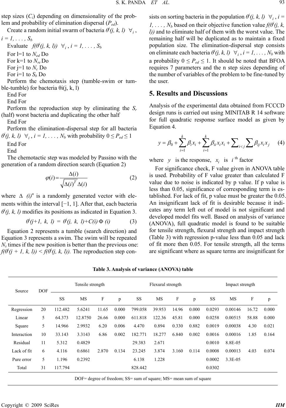 S. K. PANDA ET AL. 93 step sizes (Ci) depending on dimensionality of the prob- lem and probability of elimination dispersal (Ped). Create a random initial swarm of bacteria θi(j, k, l) i , i = 1, . . . , Sb Evaluate f(θi(j, k, l)) , i = 1, . . . , Sb i For l=1 to Ned Do For k=1 to Nre Do For j=1 to Nc Do For i=1 to Sb Do Perform the chemotaxis step (tumble-swim or tum- ble-tumble) for bacteria θi(j, k, l) End For End For Perform the reproduction step by eliminating the Sr (half) worst bacteria and duplicating the other half End For Perform the elimination-dispersal step for all bacteria θi(j, k, l) , i = 1, . . . , Nb with probability 0 ≤ Ped ≤ 1 i End For End The chemotactic step was modeled by Passino with the generation of a random direction search (Equation 2) () () () () T i i ii (2) where (i)n is a randomly generated vector with ele- ments within the interval [−1, 1]. After that, each bacteria θi(j, k, l) modifies its positions as indicated in Equation 3. θi(j+1, k, l) = θi(j, k, l)+C(i)(i) (3) Equation 2 represents a tumble (search direction) and Equation 3 represents a swim. The swim will be repeated Ns times if the new position is better than the previous one: f(θi(j + 1, k, l)) < f(θi(j, k, l)). The reproduction step con- sists on sorting bacteria in the population θi(j, k, l) i , i = 1, . . . , Nb based on their objective function value f(θi(j, k, l)) and to eliminate half of them with the worst value. The remaining half will be duplicated as to maintain a fixed population size. The elimination-dispersal step consists on eliminate each bacteria θi(j, k, l) , i = 1, . . . , Nb with a probability 0 ≤ Ped ≤ 1. It should be noted that BFOA requires 7 parameters and the n step sizes depending of the number of variables of the problem to be fine-tuned by the user. i 5. Results and Discussions Analysis of the experimental data obtained from FCCCD design runs is carried out using MINITAB R 14 software for full quadratic response surface model as given by Equation 4. 0 11 kk iiiiiiiji j ij ii y xxx x x (4) where is the response, yi x is th factor i For significance check, F value given in ANOVA table is used. Probability of F value greater than calculated F value due to noise is indicated by p value. If p value is less than 0.05, significance of corresponding term is es- tablished. For lack of fit, p value must be greater the 0.05. An insignificant lack of fit is desirable because it indi- cates any term left out of model is not significant and developed model fits well. Based on analysis of variance (ANOVA), full quadratic model is found to be suitable for tensile strength, flexural strength and impact strength (Table 3) with regression p-value less than 0.05 and lack of fit more then 0.05. For tensile strength, all the terms are significant where as square terms are insignificant for Table 3. Analysis of variance (ANOVA) table Tensile strength Flexural strength Impact strength Source DOF SS MS F p SS MS F p SS MS F p Regression 20 112.482 5.6241 11.65 0.000799.05839.95314.960.0000.0293 0.00146 16.720.000 Linear 5 64.373 12.8750 26.66 0.000 611.818 122.36 45.810.0000.0258 0.00515 58.880.000 Square 5 14.966 2.9932 6.20 0.0064.470 0.894 0.3300.8820.0019 0.00038 4.30 0.021 Interaction 10 33.143 3.3143 6.86 0.002182.77118.2776.8400.0020.0016 0.00016 1.85 0.164 Residual 11 5.312 0.4829 29.3832.671 0.0010 8.8E-05 Lack of fit 6 4.116 0.6861 2.870 0.13423.2453.8743.1600.1140.0008 0.00013 4.03 0.074 Pure error 5 1.196 0.2392 6.138 1.228 0.0002 3.3E-05 Total 31 117.794 828.442 0.0302 DOF= degree of freedom; SS= sum of square; MS= mean sum of square Copyright © 2009 SciRes IIM 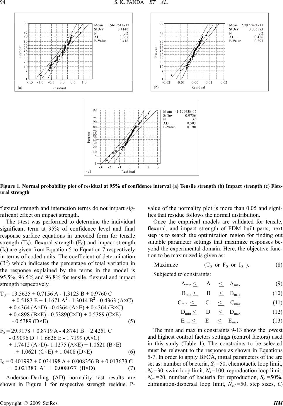 S. K. PANDA ET AL. 94 Figure 1. Normal probability plot of residual at 95% of confidence interval (a) Tensile strength (b) Impact strength (c) Flex- ural strength flexural strength and interaction terms do not impart sig- nificant effect on impact strength. The t-test was performed to determine the individual significant term at 95% of confidence level and final response surface equations in uncoded form for tensile strength (TS), flexural strength (FS) and impact strength (IS) are given from Equation 5 to Equation 7 respectively in terms of coded units. The coefficient of determination (R2) which indicates the percentage of total variation in the response explained by the terms in the model is 95.5%, 96.5% and 96.8% for tensile, flexural and impact strength respectively. TS = 13.5625 + 0.7156 A - 1.3123 B + 0.9760 C + 0.5183 E + 1.1671 A2 - 1.3014 B2 - 0.4363 (A×C) + 0.4364 (A×D) - 0.4364 (A×E) + 0.4364 (B×C) + 0.4898 (B×E) - 0.5389(C×D) + 0.5389 (C×E) - 0.5389 (D×E) (5) FS = 29.9178 + 0.8719 A - 4.8741 B + 2.4251 C - 0.9096 D + 1.6626 E - 1.7199 (A×C) + 1.7412 (A×D)- 1.1275 (A×E) + 1.0621 (B×E) + 1.0621 (C×E) + 1.0408 (D×E) (6) IS = 0.401992 + 0.034198 A + 0.008356 B + 0.013673 C + 0.021383 A2 + 0.008077 (B×D) (7) Anderson-Darling (AD) normality test results are shown in Figure 1 for respective strength residue. P- value of the normality plot is more than 0.05 and signi- fies that residue follows the normal distribution. Once the empirical models are validated for tensile, flexural, and impact strength of FDM built parts, next step is to search the optimization region for finding out suitable parameter settings that maximize responses be- yond the experimental domain. Here, the objective func- tion to be maximized is given as: Maximize (T S or FS or IS ). (8) Subjected to constraints: Amin < A < A max (9) Bmin < B < B max (10) Cmin < C < C max (11) Dmin < D < D max (12) Emin < E < E max (13) The min and max in constraints 9-13 show the lowest and highest control factors settings (control factors) used in this study (Table 1). The constraints to be selected must be relevant to the response as shown in Equations 5-7. In order to apply BFOA, initial parameters of the are set as: number of bacteria, Sb =50, chemotactic loop limit, Nc =30, swim loop limit, Ns =100, reproduction loop limit, Nre =20, number of bacteria for reproduction, Sr =50%, elimination-dispersal loop limit, Ned =50, step sizes, Ci Copyright © 2009 SciRes IIM 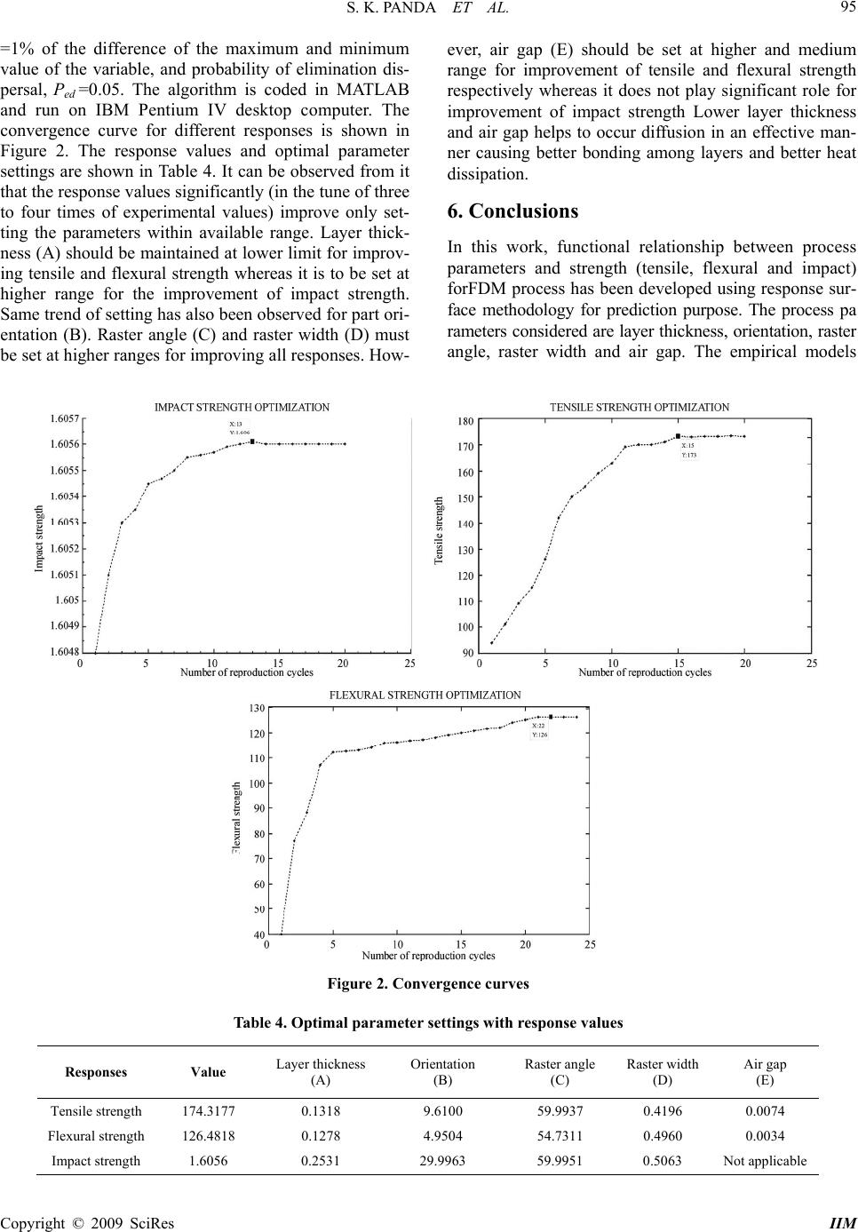 S. K. PANDA ET AL. 95 =1% of the difference of the maximum and minimum value of the variable, and probability of elimination dis- persal, Ped =0.05. The algorithm is coded in MATLAB and run on IBM Pentium IV desktop computer. The convergence curve for different responses is shown in Figure 2. The response values and optimal parameter settings are shown in Table 4. It can be observed from it that the response values significantly (in the tune of three to four times of experimental values) improve only set- ting the parameters within available range. Layer thick- ness (A) should be maintained at lower limit for improv- ing tensile and flexural strength whereas it is to be set at higher range for the improvement of impact strength. Same trend of setting has also been observed for part ori- entation (B). Raster angle (C) and raster width (D) must be set at higher ranges for improving all responses. How- ever, air gap (E) should be set at higher and medium range for improvement of tensile and flexural strength respectively whereas it does not play significant role for improvement of impact strength Lower layer thickness and air gap helps to occur diffusion in an effective man- ner causing better bonding among layers and better heat dissipation. 6. Conclusions In this work, functional relationship between process parameters and strength (tensile, flexural and impact) forFDM process has been developed using response sur- face methodology for prediction purpose. The process pa rameters considered are layer thickness, orientation, raster angle, raster width and air gap. The empirical models Figure 2. Convergence curves Table 4. Optimal parameter settings with response values Responses Value Layer thickness (A) Orientation (B) Raster angle (C) Raster width (D) Air gap (E) Tensile strength 174.3177 0.1318 9.6100 59.9937 0.4196 0.0074 Flexural strength 126.4818 0.1278 4.9504 54.7311 0.4960 0.0034 Impact strength 1.6056 0.2531 29.9963 59.9951 0.5063 Not applicable Copyright © 2009 SciRes IIM 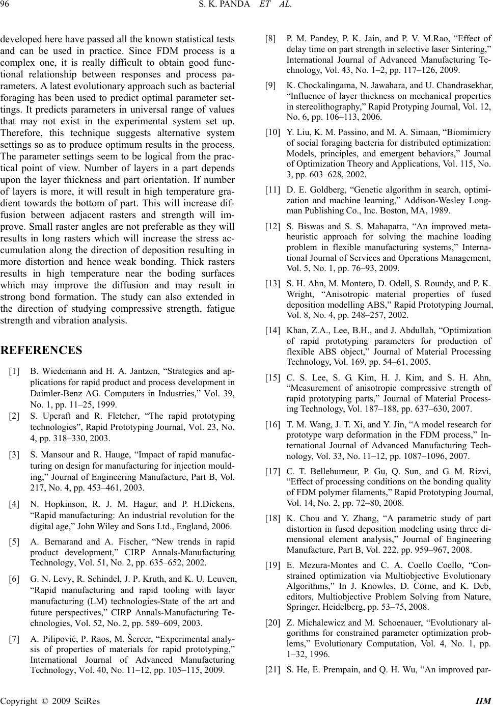 S. K. PANDA ET AL. 96 developed here have passed all the known statistical tests and can be used in practice. Since FDM process is a complex one, it is really difficult to obtain good func- tional relationship between responses and process pa- rameters. A latest evolutionary approach such as bacterial foraging has been used to predict optimal parameter set- tings. It predicts parameters in universal range of values that may not exist in the experimental system set up. Therefore, this technique suggests alternative system settings so as to produce optimum results in the process. The parameter settings seem to be logical from the prac- tical point of view. Number of layers in a part depends upon the layer thickness and part orientation. If number of layers is more, it will result in high temperature gra- dient towards the bottom of part. This will increase dif- fusion between adjacent rasters and strength will im- prove. Small raster angles are not preferable as they will results in long rasters which will increase the stress ac- cumulation along the direction of deposition resulting in more distortion and hence weak bonding. Thick rasters results in high temperature near the boding surfaces which may improve the diffusion and may result in strong bond formation. The study can also extended in the direction of studying compressive strength, fatigue strength and vibration analysis. REFERENCES [1] B. Wiedemann and H. A. Jantzen, “Strategies and ap- plications for rapid product and process development in Daimler-Benz AG. Computers in Industries,” Vol. 39, No. 1, pp. 11–25, 1999. [2] S. Upcraft and R. Fletcher, “The rapid prototyping technologies”, Rapid Prototyping Journal, Vol. 23, No. 4, pp. 318–330, 2003. [3] S. Mansour and R. Hauge, “Impact of rapid manufac- turing on design for manufacturing for injection mould- ing,” Journal of Engineering Manufacture, Part B, Vol. 217, No. 4, pp. 453–461, 2003. [4] N. Hopkinson, R. J. M. Hagur, and P. H.Dickens, “Rapid manufacturing: An industrial revolution for the digital age,” John Wiley and Sons Ltd., England, 2006. [5] A. Bernarand and A. Fischer, “New trends in rapid product development,” CIRP Annals-Manufacturing Technology, Vol. 51, No. 2, pp. 635–652, 2002. [6] G. N. Levy, R. Schindel, J. P. Kruth, and K. U. Leuven, “Rapid manufacturing and rapid tooling with layer manufacturing (LM) technologies-State of the art and future perspectives,” CIRP Annals-Manufacturing Te- chnologies, Vol. 52, No. 2, pp. 589–609, 2003. [7] A. Pilipović, P. Raos, M. Šercer, “Experimental analy- sis of properties of materials for rapid prototyping,” International Journal of Advanced Manufacturing Technology, Vol. 40, No. 11–12, pp. 105–115, 2009. [8] P. M. Pandey, P. K. Jain, and P. V. M.Rao, “Effect of delay time on part strength in selective laser Sintering,” International Journal of Advanced Manufacturing Te- chnology, Vol. 43, No. 1–2, pp. 117–126, 2009. [9] K. Chockalingama, N. Jawahara, and U. Chandrasekhar, “Influence of layer thickness on mechanical properties in stereolithography,” Rapid Protyping Journal, Vol. 12, No. 6, pp. 106–113, 2006. [10] Y. Liu, K. M. Passino, and M. A. Simaan, “Biomimicry of social foraging bacteria for distributed optimization: Models, principles, and emergent behaviors,” Journal of Optimization Theory and Applications, Vol. 115, No. 3, pp. 603–628, 2002. [11] D. E. Goldberg, “Genetic algorithm in search, optimi- zation and machine learning,” Addison-Wesley Long- man Publishing Co., Inc. Boston, MA, 1989. [12] S. Biswas and S. S. Mahapatra, “An improved meta- heuristic approach for solving the machine loading problem in flexible manufacturing systems,” Interna- tional Journal of Services and Operations Management, Vol. 5, No. 1, pp. 76–93, 2009. [13] S. H. Ahn, M. Montero, D. Odell, S. Roundy, and P. K. Wright, “Anisotropic material properties of fused deposition modelling ABS,” Rapid Prototyping Journal, Vol. 8, No. 4, pp. 248–257, 2002. [14] Khan, Z.A., Lee, B.H., and J. Abdullah, “Optimization of rapid prototyping parameters for production of flexible ABS object,” Journal of Material Processing Technology, Vol. 169, pp. 54–61, 2005. [15] C. S. Lee, S. G. Kim, H. J. Kim, and S. H. Ahn, “Measurement of anisotropic compressive strength of rapid prototyping parts,” Journal of Material Process- ing Technology, Vol. 187–188, pp. 637–630, 2007. [16] T. M. Wang, J. T. Xi, and Y. Jin, “A model research for prototype warp deformation in the FDM process,” In- ternational Journal of Advanced Manufacturing Tech- nology, Vol. 33, No. 11–12, pp. 1087–1096, 2007. [17] C. T. Bellehumeur, P. Gu, Q. Sun, and G. M. Rizvi, “Effect of processing conditions on the bonding quality of FDM polymer filaments,” Rapid Prototyping Journal, Vol. 14, No. 2, pp. 72–80, 2008. [18] K. Chou and Y. Zhang, “A parametric study of part distortion in fused deposition modeling using three di- mensional element analysis,” Journal of Engineering Manufacture, Part B, Vol. 222, pp. 959–967, 2008. [19] E. Mezura-Montes and C. A. Coello Coello, “Con- strained optimization via Multiobjective Evolutionary Algorithms,” In J. Knowles, D. Corne, and K. Deb, editors, Multiobjective Problem Solving from Nature, Springer, Heidelberg, pp. 53–75, 2008. [20] Z. Michalewicz and M. Schoenauer, “Evolutionary al- gorithms for constrained parameter optimization prob- lems,” Evolutionary Computation, Vol. 4, No. 1, pp. 1–32, 1996. [21] S. He, E. Prempain, and Q. H. Wu, “An improved par- Copyright © 2009 SciRes IIM  S. K. PANDA ET AL. 97 ticle swarm optimizer for mechanical design optimiza- tion problems,” Engineering Optimization, Vol. 36, No. 5, pp. 585–605, 2004. [22] T. Ray and K. Liew, “Society and civilization: an opti- mization algorithm based on the simulation of social behavior,” IEEE Transactions on Evolutionary Com- putation, Vol. 7, No. 4, pp. 386–396, 2003. [23] J. Kennedy and R. C. Eberhart, “Swarm intelligence,” Morgan Kaufmann, UK, 2001. [24] G. Leguizamón and C. Coello-Coello, “A boundary search based ACO algorithm coupled with stochastic ranking,” In 2007 IEEE Congress on Evolutionary Computation (CEC’07), Singapore, September 2007. IEEE Press, pp. 165–172, 2007. [25] D. Karaboga and B. Basturk, “On the performance of artificial bee colony (ABC) algorithm,” Applied Soft Computing, Vol. 8, No. 1, pp. 687–697, 2008. [26] K. Passino, “Biomimicry of bacterial foraging for dis- tributed optimization and control,” IEEE Control Sys- tems Magazine, Vol. 22, No. 3, pp. 52–67, 2002. [27] R. Majhi, G. Panda, G. Sahoo, P. Dash, and D. Das, “Stock market prediction of s&p 500 and DJIA using bacterial foraging optimization technique,” In Pro- ceedings of the IEEE Congress on Evolutionary Com- putation (CEC’07), Singapore, IEEE Service Center, pp. 2569-2575, September 2007. [28] S. Mishra, G. D. Reddy, P. E. Rao, and K. Santosh, “Implementation of new evolutionary techniques for transmission loss reduction,” In Proceedings of the IEEE Congress on Evolutionary Computation (CEC’ 07), Singapore, IEEE Service Center, pp. 2331–2336, September 2007. [29] B. Majhi and G. Panda, “Bacteria foraging based iden- tificacion of nonlinear dynamic system,” In Proceed- ings of the IEEE Congress on Evolutionary Computa- tion (CEC’07), Singapore, IEEE Service Center, pp. 1636–1641, September 2007. [30] D. C. Montgomery, “Design and Analysis of Experi- ments”, Fifth Edition, John Wiley and Sons Pvt. Ltd., Singapore, 2003. Copyright © 2009 SciRes IIM |

