Paper Menu >>
Journal Menu >>
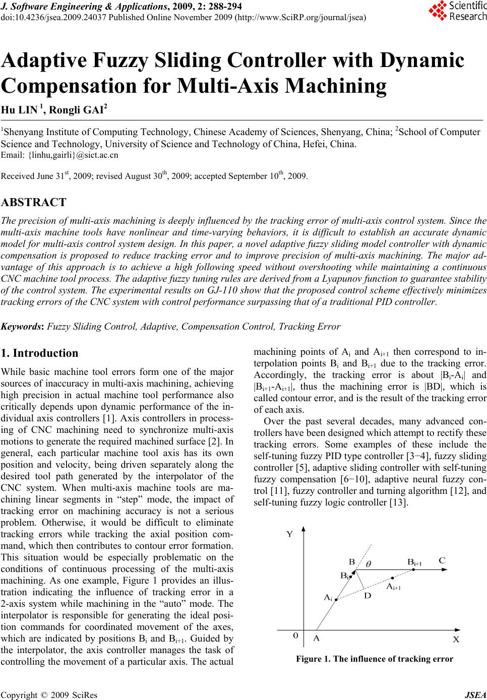 J. Software Engineering & Applications, 2009, 2: 288-294 doi:10.4236/jsea.2009.24037 Published Online November 2009 (http://www.SciRP.org/journal/jsea) Copyright © 2009 SciRes JSEA Adaptive Fuzzy Sliding Controller with Dynamic Compensation for Multi-Axis Machining Hu LIN 1, Rongli GAI2 1Shenyang Institute of Computing Technology, Chinese Academy of Sciences, Shenyang, China; 2School of Computer Science and Technology, University of Science and Technology of China, Hefei, China. Email: {linhu,gairli}@sict.ac.cn Received June 31st, 2009; revised August 30th, 2009; accepted September 10th, 2009. ABSTRACT The precision of multi-axis machining is deeply influenced by the tracking error of multi-axis control system. Since the multi-axis machine tools have nonlinear and time-varying behaviors, it is difficult to establish an accurate dynamic model for multi-axis control system design. In this paper, a novel adaptive fuzzy sliding model controller with dynamic compensation is proposed to reduce tracking error and to improve precision of multi-axis machining. The major ad- vantage of this approach is to achieve a high following speed without overshooting while maintaining a continuous CNC machine tool process. The adaptive fuzzy tuning rules are derived from a Lyapunov function to guarantee stability of the control system. The experimental results on GJ-110 show that the proposed control scheme effectively minimizes tracking errors of the CNC system with control performance surpassing that of a traditional PID controller. Keywords: Fuzzy Sliding Control, Adaptive, Compensation Control, Tracking Error 1. Introduction While basic machine tool errors form one of the major sources of inaccuracy in multi-axis machining, achieving high precision in actual machine tool performance also critically depends upon dynamic performance of the in- dividual axis controllers [1]. Axis controllers in process- ing of CNC machining need to synchronize multi-axis motions to generate the required machined surface [2]. In general, each particular machine tool axis has its own position and velocity, being driven separately along the desired tool path generated by the interpolator of the CNC system. When multi-axis machine tools are ma- chining linear segments in “step” mode, the impact of tracking error on machining accuracy is not a serious problem. Otherwise, it would be difficult to eliminate tracking errors while tracking the axial position com- mand, which then contributes to contour error formation. This situation would be especially problematic on the conditions of continuous processing of the multi-axis machining. As one example, Figure 1 provides an illus- tration indicating the influence of tracking error in a 2-axis system while machining in the “auto” mode. The interpolator is responsible for generating the ideal posi- tion commands for coordinated movement of the axes, which are indicated by positions Bi and Bi+1. Guided by the interpolator, the axis controller manages the task of controlling the movement of a particular axis. The actual machining points of Ai and Ai+1 then correspond to in- terpolation points Bi and Bi+1 due to the tracking error. Accordingly, the tracking error is about |Bi-Ai| and |Bi+1-Ai+1|, thus the machining error is |BD|, which is called contour error, and is the result of the tracking error of each axis. Over the past several decades, many advanced con- trollers have been designed which attempt to rectify these tracking errors. Some examples of these include the self-tuning fuzzy PID type controller [3−4], fuzzy sliding controller [5], adaptive sliding controller with self-tuning fuzzy compensation [6−10], adaptive neural fuzzy con- trol [11], fuzzy controller and turning algorithm [12], and self-tuning fuzzy logic controller [13]. Figure 1. The influence of tracking error 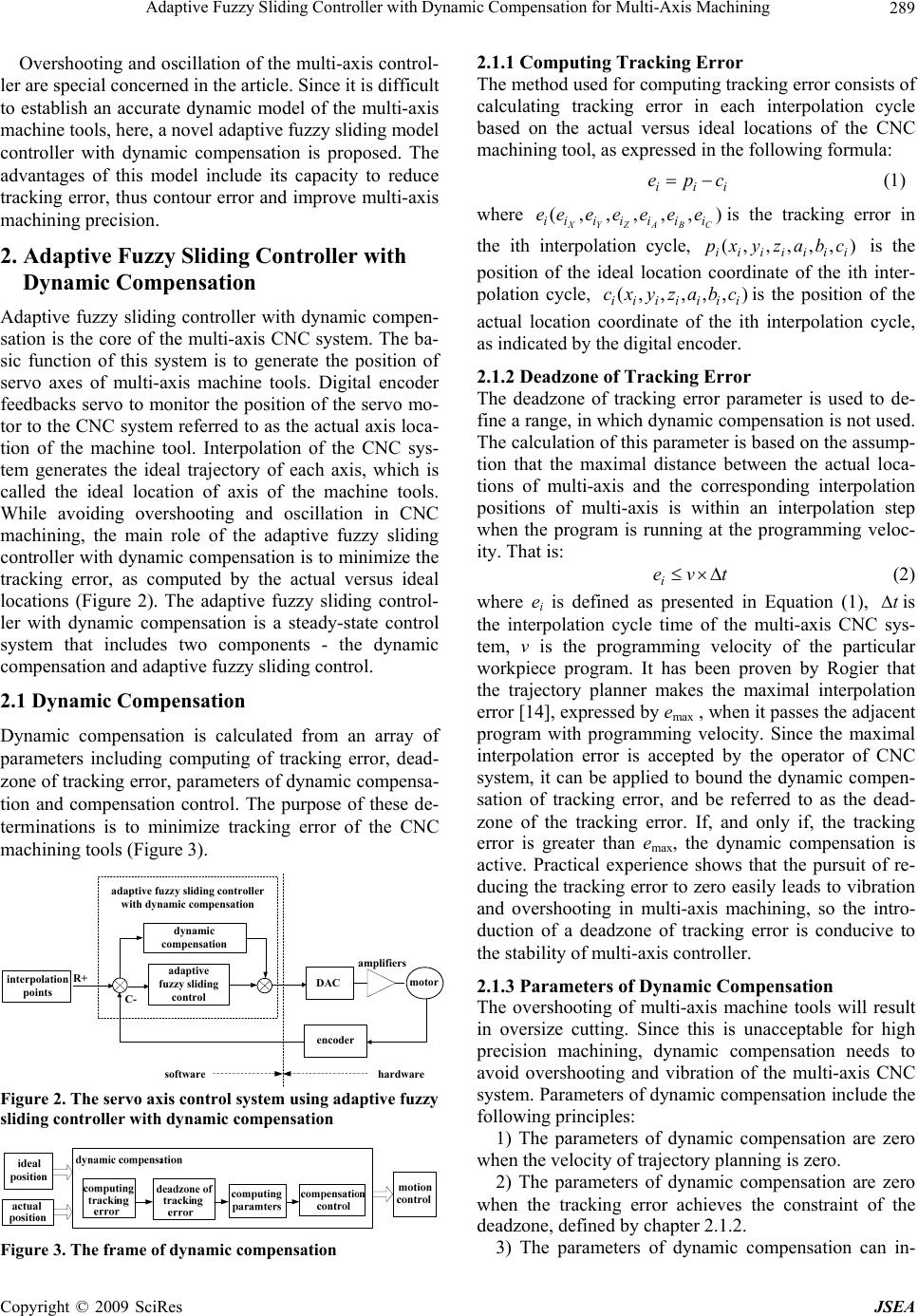 Adaptive Fuzzy Sliding Controller with Dynamic Compensation for Multi-Axis Machining 289 Overshooting and oscillation of the multi-axis control- ler are special concerned in the article. Since it is difficult to establish an accurate dynamic model of the multi-axis machine tools, here, a novel adaptive fuzzy sliding model controller with dynamic compensation is proposed. The advantages of this model include its capacity to reduce tracking error, thus contour error and improve multi-axis machining precision. 2. Adaptive Fuzzy Sliding Controller with Dynamic Compensation Adaptive fuzzy sliding controller with dynamic compen- sation is the core of the multi-axis CNC system. The ba- sic function of this system is to generate the position of servo axes of multi-axis machine tools. Digital encoder feedbacks servo to monitor the position of the servo mo- tor to the CNC system referred to as the actual axis loca- tion of the machine tool. Interpolation of the CNC sys- tem generates the ideal trajectory of each axis, which is called the ideal location of axis of the machine tools. While avoiding overshooting and oscillation in CNC machining, the main role of the adaptive fuzzy sliding controller with dynamic compensation is to minimize the tracking error, as computed by the actual versus ideal locations (Figure 2). The adaptive fuzzy sliding control- ler with dynamic compensation is a steady-state control system that includes two components - the dynamic compensation and adaptive fuzzy sliding control. 2.1 Dynamic Compensation Dynamic compensation is calculated from an array of parameters including computing of tracking error, dead- zone of tracking error, parameters of dynamic compensa- tion and compensation control. The purpose of these de- terminations is to minimize tracking error of the CNC machining tools (Figure 3). adaptive fuzzy sliding co nt ro ller with dynam ic compens a ti o n adaptive fuzzy sliding control DAC encoder amplifiers hardwaresoftware R+ C- dynamic compensation motor interpolation points Figure 2. The servo axis control system using adaptive fuzzy sliding controller with dynamic compensation Figure 3. The frame of dynamic compensation 2.1.1 Computing Tracking E r ror The method used for computing tracking error consists of calculating tracking error in each interpolation cycle based on the actual versus ideal locations of the CNC machining tool, as expressed in the following formula: iii cpe (1) where ),,,,,( CBAZYX iiiiiii eeeeeee is the tracking error in the ith interpolation cycle, ),,,,,( iiiiiii cba z y x p is the position of the ideal location coordinate of the ith inter- polation cycle, ),,,,,(iiiiiii cba z y x cis the position of the actual location coordinate of the ith interpolation cycle, as indicated by the digital encoder. 2.1.2 Deadzone of Tracking Error The deadzone of tracking error parameter is used to de- fine a range, in which dynamic compensation is not used. The calculation of this parameter is based on the assump- tion that the maximal distance between the actual loca- tions of multi-axis and the corresponding interpolation positions of multi-axis is within an interpolation step when the program is running at the programming veloc- ity. That is: tvei (2) where ei is defined as presented in Equation (1), t is the interpolation cycle time of the multi-axis CNC sys- tem, v is the programming velocity of the particular workpiece program. It has been proven by Rogier that the trajectory planner makes the maximal interpolation error [14], expressed by emax , when it passes the adjacent program with programming velocity. Since the maximal interpolation error is accepted by the operator of CNC system, it can be applied to bound the dynamic compen- sation of tracking error, and be referred to as the dead- zone of the tracking error. If, and only if, the tracking error is greater than e max, the dynamic compensation is active. Practical experience shows that the pursuit of re- ducing the tracking error to zero easily leads to vibration and overshooting in multi-axis machining, so the intro- duction of a deadzone of tracking error is conducive to the stability of multi-axis controller. 2.1.3 Parameters of Dynamic Compensation The overshooting of multi-axis machine tools will result in oversize cutting. Since this is unacceptable for high precision machining, dynamic compensation needs to avoid overshooting and vibration of the multi-axis CNC system. Parameters of dynamic compensation include the following principles: 1) The parameters of dynamic compensation are zero when the velocity of trajectory planning is zero. 2) The parameters of dynamic compensation are zero when the tracking error achieves the constraint of the deadzone, defined by chapter 2.1.2. 3) The parameters of dynamic compensation can in- Copyright © 2009 SciRes JSEA  Adaptive Fuzzy Sliding Controller with Dynamic Compensation for Multi-Axis Machining 290 crease in a step-wise manner when the multi-axis CNC system is running in an acceleration phase. 4) The parameters of dynamic compensation require a step-wise reduction when the multi-axis CNC system is running in a deceleration phase. 5) The parameters of dynamic compensation achieve a peak value when the multi-axis CNC system is running in the programming velocity. Based on the principles of dynamic compensation, the following function can be selected as the parameter of dynamic compensation: max elee v v comp ii i i (3) Where vi is the velocity in the ith trajectory cycle, lei is the length of the tracking error of multi-axis in the tra- jectory cycle, defined by Equation (4), ,( X ii compcomp ) ,,,, CBAZY iiiii compcompcompcompcompif the parameter of dynamic compensation is in the trajectory cycle. 222222 CBAZYX iiiiiii eeeeeele (4) 2.1.4 Compensation Contr ol The output of the adaptive fuzzy sliding controller with dynamic compensation for multi-axis machining pro- posed in this paper can be expressed by the following equation: uuu ccol (5) Where ucol is the total output of the position controller of the multi-axis CNC system, ucis the output of the dy- namic compensation controller and u is the output of the adaptive fuzzy sliding controller. We can define the rules for compensation control as follows: max max 00 eleu elecompku ic iipc (6) Where kp is the proportional gain of the CNC system, while the meanings of other variables are presented as Equation (3), (4) and (5). The dynamic compensation controller adds a compen- sation variable to each axis according to the vector of the multi-axis tracking error. It can produce a rapid reduction in the tracking error while simultaneously reducing the frequency of adjusting parameters of the adaptive fuzzy sliding controller. In addition, the dynamic compensation controller can improve the stability of the numerical multi-axis control system. 2.2 Adaptive Fuzzy Sliding There exist a number of nonlinearities and uncertainties in the multi-axis control system. These result from struc- tural or unstructured uncertainties, such as backlash, saturation and friction. It is very difficult to establish the boundary for these nonlinearities and uncertainties in the CNC system, particularly in a multi-axis system. Dy- namic compensation parameters are changed according to the trajectory velocity and therefore can contribute to an increase in the uncertainty of the multi-axis system. As an approach to rectify these problems, an adaptive fuzzy sliding control structure is proposed. This structure is referred to as adaptive fuzzy sliding controller with dynamic compensation since it incorporated the dynamic compensation algorithm discussed above. Dynamic systems with multiple kinds of nonlinearities and uncertainties, such as multi-axis machine systems, can be expressed as the following Formula [15–17]: () ˆ ()( ,)( ,) n x tfXt fXtu (7) Where (1) ( ,,.......,) nT Xxxx is the state of the system and n uR and n x R are the control inputs and out- puts of the system, respectively. The nonlinear model system consists of the reference model ˆ(,) f Xt and mul- tiple nonlinearities and uncertainties (,) f Xt, which include the dynamic compensation and inherent nonlin- ear characteristics of the multi-axis CNC system. A hy- pothesis can be proposed based on: (,) (,) f xtF xt (8) The time-varying sliding surface is defined as: 1 (,) 0. n d sxt e dt (9) It is referred to as the sliding switching line in 2D space, where λ is a positive constant and Tn deeeXXe ),...,,( )1( is the tracking error vector. In general, when considering second-order system as an example, the ideal fuzzy sliding control law is: ),(),(),( ˆ * ssatxxkextXfud (10) Where ),( xxk and ),( ssat are defined as: (, )()kxxFx (11) 1, 1 (, ),11 1, 1 s sat sss s (12) And η is a positive constant, while φ is the thickness of the boundary layer. Suppose: 12 12 2 1 2 11 1 () () (( li i li i i A i mm i A ll i x x )) x (13) Copyright © 2009 SciRes JSEA 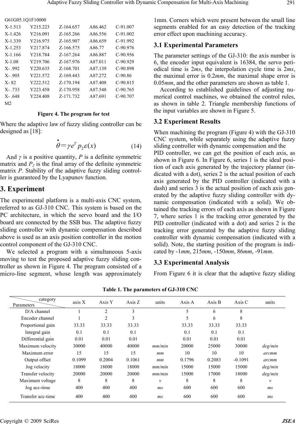 Adaptive Fuzzy Sliding Controller with Dynamic Compensation for Multi-Axis Machining Copyright © 2009 SciRes JSEA 291 1mm. Corners which were present between the small line segments enabled for an easy detection of the tracking error effect upon machining accuracy. G61G05.1Q1F10000 X-1.513 Y215.223 Z-164.657 A86.462 C-91.007 X-1.426 Y216.091 Z-165.266 A86.556 C-91.002 X-1.339 Y216.975 Z-165.907 A86.659 C-91.992 X-1.253 Y217.874 Z-166.575 A86.77 C-90.976 X-1.166 Y218.784 Z-167.264 A86.887 C-90.956 X-1.08 Y219.706 Z-167.976 A87.011 C-90.929 X- .992 Y220.635 Z-168.701 A87.139 C-90.898 X- .905 Y221.572 Z-169.443 A87.272 C-90.86 X- 82 Y222.512 Z-170.194 A87.408 C-90.815 X- .733 Y223.458 Z-170.958 A87.548 C-90.765 X- .648 Y224.408 Z-171.732 A87.691 C-90.707 M2 3.1 Experimental Parameters The parameter settings of the GJ-310: the axis number is 6, the encoder input equivalent is 16384, the servo peri- odical time is 2ms, the interpolation cycle time is 2ms, the maximal error is 0.2mm , the maximal shape error is 0.05mm, and the other parameters are shown as table 1. According to established guidelines of adjusting nu- merical control machines, we obtained the control rules, as shown in table 2. Triangle membership functions of the input variables are shown in Figure 5. Figure 4. The program for test 3.2 Experiment Results Where the adaptive law of fuzzy sliding controller can be designed as [18]: When machining the program (Figure 4) with the GJ-310 CNC system, while separately using the adaptive fuzzy sliding controller with dynamic compensation and the 2() T ep x = (14) PID controller, we can get the position of each axis, as shown in Figure 6. In Figure 6, series 1 is the ideal posi- tion of each axis generated by the trajectory planner (in- dicated with a dot), series 2 is the actual position of each axis generated by the PID controller (indicated with a dash) and series 3 is the actual position of each axis gen- erated by the adaptive fuzzy sliding controller with dy- namic compensation (indicated with a solid). We ob- tained the tracking errors of each axis as shown in Figure 7, where series 1 is the tracking error generated by the PID controller (indicated with a dot) and series 2 is the tracking error generated by the adaptive fuzzy sliding controller with dynamic compensation (indicated with a solid). Note, the starting position of the program is indi- cated by -1mm, 215mm, -150mm, 86mm, -91mm. And γ is a positive quantity, P is a definite symmetric matrix and P2 is the final array of the definite symmetric matrix P. Stability of the adaptive fuzzy sliding control- ler is guaranteed by the Lyapunov function. 3. Experiment The experimental platform is a multi-axis CNC system, referred to as GJ-310 CNC. This system is based on the PC architecture, in which the servo board and the I/O board are connected by the SSB bus. The adaptive fuzzy sliding controller with dynamic compensation described above is used as an axis position controller in the motion control component of the GJ-310 CNC. We selected a program with a simultaneous 5-axis moving to test the proposed adaptive fuzzy sliding con- troller as shown in Figure 4. The program consisted of a micro-line segment, whose length was approximately 3.3 Experimental Analysis From Figure 6 it is clear that the adaptive fuzzy sliding Table 1. The parameters of GJ-310 CNC category Parameters axis X Axis Y Axis Z units Axis A Axis B Axis C units D/A channel 1 2 3 5 6 8 Encoder channel 1 2 3 5 6 8 Proportional gain 33.33 33.33 33.33 33.33 33.33 33.33 Integral gain 0.1 0.1 0.1 0.1 0.1 0.1 Differential gain 0.01 0.01 0.01 0.01 0.01 0.01 Maximum velocity 30000 40000 40000 mm/min 20000 25000 30000 deg/min Maximum error 15 15 15 mm 10 10 10 arcmm Output offset 0.1099 0.2004 0.1061 mm 0.1796 0.2083 -0.1091 arcmm Jog velocity 18000 18000 18000 mm/min 15000 15000 15000 deg/min Transfer velocity 20000 20000 20000 mm/min 15000 17000 18000 deg/min Maximum voltage 8 8 8 v 8 8 8 v Jog acc-time 400 400 400 ms 600 600 600 ms Transfer acc-time 400 400 400 ms 600 600 600 ms  Adaptive Fuzzy Sliding Controller with Dynamic Compensation for Multi-Axis Machining 292 Table 2. The control rules Error change rate ∆e The output u LN MN SN ZZ SP MPLP LP LP LP LP LP LP LP LP MP SP SP SP MP MP LP LP SP ZZ SP SP SP MP MPLP ZZ ZZ ZZ ZZ ZZ ZZ ZZZZ SN LN MN MN SN SN SNZZ MN LN LN MN MN SN SNSN The Tracking Error e LN LN LN LN LN LN LNLN Figure 5. The triangle membership functions of the input variables controller with dynamic compensation and the PID con- troller produce nearly identical ending points. Moreover, use of the adaptive fuzzy sliding controller with dynamic compensation results in smooth control, thereby produc- ing an accurate tracking of the trajectory with no over- shooting or vibration in the machining. From Figure 7 it is apparent that the adaptive fuzzy sliding controller with dynamic compensation can reduce tracking errors of each servo axis. As one example of the program, an examination of axis Z which has the longest moving trajectory, provides for a means of comparison of the effects between the two controllers. The adaptive fuzzy sliding controller with dynamic compensation re- duced the tracking error by almost 44% of the PID con- troller and the tracking error of axis C, whose moving trajectory was the shortest in the example of program, was reduced by about 19% of the PID controller. From the above simulation results, the proposed adap- tive fuzzy sliding controller with dynamic compensation demonstrates a perfect performance, which can abolish effects of the system trace performance caused by track- ing nonlinearities and uncertainties disturbances. In this way, the control system can produce a high degree of precision in multi-axis machining. 4. Conclusions Strictly speaking, the CNC system typically has more than one axis. Therefore, an ideal linear system is not available. In this way, research is directed at resolving nonlinearity and uncertainty control problems of multi- axis machining tools, and reducing tracking errors of multi-axis. CNC systems have important implications for Figure 6. The position of each axis Copyright © 2009 SciRes JSEA 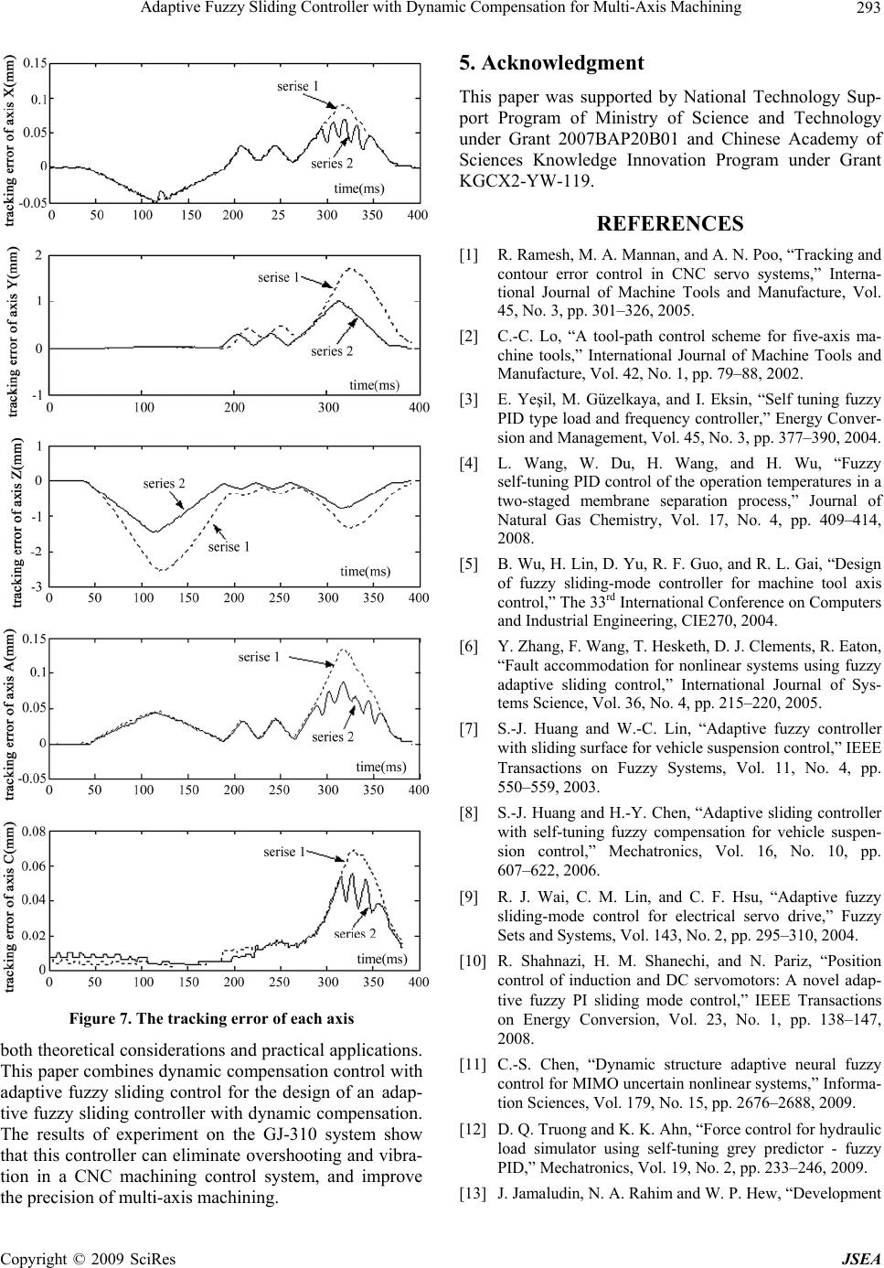 Adaptive Fuzzy Sliding Controller with Dynamic Compensation for Multi-Axis Machining 293 Figure 7. The tracking error of each axis both theoretical considerations and practical applications. This paper combines dynamic compensation control with adaptive fuzzy sliding control for the design of an adap- tive fuzzy sliding controller with dynamic compensation. The results of experiment on the GJ-310 system show that this controller can eliminate overshooting and vibra- tion in a CNC machining control system, and improve the precision of multi-axis machining. 5. Acknowledgment This paper was supported by National Technology Sup- port Program of Ministry of Science and Technology under Grant 2007BAP20B01 and Chinese Academy of Sciences Knowledge Innovation Program under Grant KGCX2-YW-119. REFERENCES [1] R. Ramesh, M. A. Mannan, and A. N. Poo, “Tracking and contour error control in CNC servo systems,” Interna- tional Journal of Machine Tools and Manufacture, Vol. 45, No. 3, pp. 301–326, 2005. [2] C.-C. Lo, “A tool-path control scheme for five-axis ma- chine tools,” International Journal of Machine Tools and Manufacture, Vol. 42, No. 1, pp. 79–88, 2002. [3] E. Yeşil, M. Güzelkaya, and I. Eksin, “Self tuning fuzzy PID type load and frequency controller,” Energy Conver- sion and Management, Vol. 45, No. 3, pp. 377–390, 2004. [4] L. Wang, W. Du, H. Wang, and H. Wu, “Fuzzy self-tuning PID control of the operation temperatures in a two-staged membrane separation process,” Journal of Natural Gas Chemistry, Vol. 17, No. 4, pp. 409–414, 2008. [5] B. Wu, H. Lin, D. Yu, R. F. Guo, and R. L. Gai, “Design of fuzzy sliding-mode controller for machine tool axis control,” The 33rd International Conference on Computers and Industrial Engineering, CIE270, 2004. [6] Y. Zhang, F. Wang, T. Hesketh, D. J. Clements, R. Eaton, “Fault accommodation for nonlinear systems using fuzzy adaptive sliding control,” International Journal of Sys- tems Science, Vol. 36, No. 4, pp. 215–220, 2005. [7] S.-J. Huang and W.-C. Lin, “Adaptive fuzzy controller with sliding surface for vehicle suspension control,” IEEE Transactions on Fuzzy Systems, Vol. 11, No. 4, pp. 550–559, 2003. [8] S.-J. Huang and H.-Y. Chen, “Adaptive sliding controller with self-tuning fuzzy compensation for vehicle suspen- sion control,” Mechatronics, Vol. 16, No. 10, pp. 607–622, 2006. [9] R. J. Wai, C. M. Lin, and C. F. Hsu, “Adaptive fuzzy sliding-mode control for electrical servo drive,” Fuzzy Sets and Systems, Vol. 143, No. 2, pp. 295–310, 2004. [10] R. Shahnazi, H. M. Shanechi, and N. Pariz, “Position control of induction and DC servomotors: A novel adap- tive fuzzy PI sliding mode control,” IEEE Transactions on Energy Conversion, Vol. 23, No. 1, pp. 138–147, 2008. [11] C.-S. Chen, “Dynamic structure adaptive neural fuzzy control for MIMO uncertain nonlinear systems,” Informa- tion Sciences, Vol. 179, No. 15, pp. 2676–2688, 2009. [12] D. Q. Truong and K. K. Ahn, “Force control for hydraulic load simulator using self-tuning grey predictor - fuzzy PID,” Mechatronics, Vol. 19, No. 2, pp. 233–246, 2009. [13] J. Jamaludin, N. A. Rahim and W. P. Hew, “Development Copyright © 2009 SciRes JSEA  Adaptive Fuzzy Sliding Controller with Dynamic Compensation for Multi-Axis Machining Copyright © 2009 SciRes JSEA 294 of a self-tuning fuzzy logic controller for intelligent con- trol of elevator systems,” Engineering Applications of Artificial Intelligence, pp. 1–12, 2009. [14] R. S. Blom, “Design and development of a real-time tra- jectory planner for the enhanced machine controller,” In- telligent Systems Division Gaithersburg, Maryland United States of America : National Institute of Standards and Technology Manufacturing Engineering Laboratory, 1999. [15] J. E. Slotine, “Sliding controller design for nonlinear systems,” International Journal of Control, Vol. 40, No. 2, pp. 421–434, 1984. [16] C. L. Hwang and C. Y. Kuo, “A stable adaptive fuzzy sliding mode control for affine nonlinear systems with application to four-bar linkage systems,” IEEE Transac- tions on Fuzzy Systems, Vol. 9, No. 2, pp. 238–252, 2001. [17] I. Eker, S. A. Akinal, “Sliding mode control with integral augmented sliding surface: Design and experimental ap- plication to an electromechanical system,” Electrical En- gineering, Vol. 90, No. 3, pp. 189–197, 2008. [18] R. L. Gai, H. Lin, X. P. Qin, D. Yu, and R. F. Guo, “Adaptive fuzzy sliding control design for the axis system with dynamic multiple kinds of nonlinearities and uncer- tainties,” Proceedings of the 38th International Confer- ence on Computers and Industrial Engineering. Vol. 3, pp. 3006–3011, 2008. |