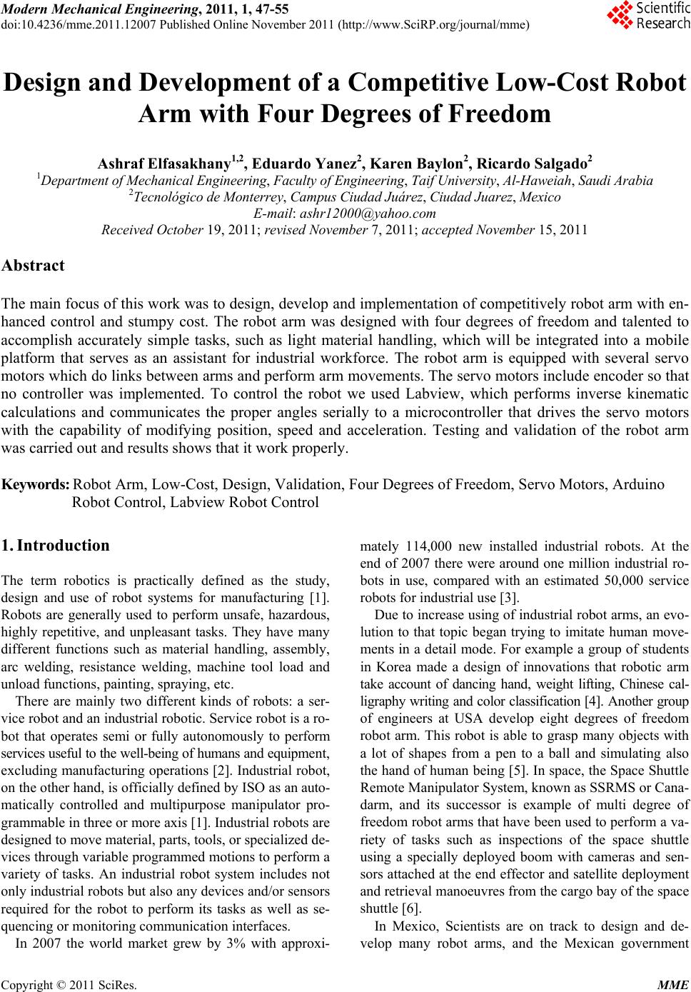
 Modern Mechanical Engineering, 2011, 1, 47-55 doi:10.4236/mme.2011.12007 Published Online November 2011 (http://www.SciRP.org/journal/mme) Copyright © 2011 SciRes. MME Design and Development of a Competitive Low-Cost Robot Arm with Four Degrees of Freedom Ashraf Elfasakhany1,2, Eduardo Yanez2, Karen Baylon2, Ricardo Salgado2 1Department of Mechanical Engineering, Faculty of Engineering, Taif University, Al-Haweiah, Saudi Arabia 2Tecnológico de Monterrey, Campus Ciudad Juárez, Ciudad Juarez, Mexico E-mail: ashr12000@yahoo.com Received October 19, 2011; revised November 7, 2011; accepted November 15, 2011 Abstract The main focus of this work was to design, develop and implementation of competitively robot arm with en- hanced control and stumpy cost. The robot arm was designed with four degrees of freedom and talented to accomplish accurately simple tasks, such as light material handling, which will be integrated into a mobile platform that serves as an assistant for industrial workforce. The robot arm is equipped with several servo motors which do links between arms and perform arm movements. The servo motors include encoder so that no controller was implemented. To control the robot we used Labview, which performs inverse kinematic calculations and communicates the proper angles serially to a microcontroller that drives the servo motors with the capability of modifying position, speed and acceleration. Testing and validation of the robot arm was carried out and results shows that it work properly. Keywords: Robot Arm, Low-Cost, Design, Validation, Four Degrees of Freedom, Servo Motors, Arduino Robot Control, Labview Robot Control 1. Introduction The term robotics is practically defined as the study, design and use of robot systems for manufacturing [1]. Robots are generally used to perform unsafe, hazardous, highly repetitive, and unpleasant tasks. They have many different functions such as material handling, assembly, arc welding, resistance welding, machine tool load and unload functions, painting, spraying, etc. There are mainly two different kinds of robots: a ser- vice robot and an industrial robotic. Service robot is a ro- bot that operates semi or fully autonomously to perform services useful to the well-being of humans and equipment, excluding manufacturing operations [2]. Industrial robot, on the other hand, is officially defined by ISO as an auto- matically controlled and multipurpose manipulator pro- grammable in three or more axis [1]. Industrial robots are designed to move material, parts, tools, or specialized de- vices through variable programmed motions to perform a variety of tasks. An industrial robot system includes not only industrial robots but also any devices and/or sensors required for the robot to perform its tasks as well as se- quencing or monitoring communication interfaces. In 2007 the world market grew by 3% with approxi- mately 114,000 new installed industrial robots. At the end of 2007 there were around one million industrial ro- bots in use, compared with an estimated 50,000 service robots for industrial use [3]. Due to increase using of industrial robot arms, an evo- lution to that topic began trying to imitate human move- ments in a detail mode. For example a group of students in Korea made a design of innovations that robotic arm take account of dancing hand, weight lifting, Chinese cal- ligraphy writing and color classification [4]. Another group of engineers at USA develop eight degrees of freedom robot arm. This robot is able to grasp many objects with a lot of shapes from a pen to a ball and simulating also the hand of human being [5]. In space, the Space Shuttle Remote Manipulator System, known as SSRMS or Cana- darm, and its successor is example of multi degree of freedom robot arms that have been used to perform a va- riety of tasks such as inspections of the space shuttle using a specially deployed boom with cameras and sen- sors attached at the end effector and satellite deployment and retrieval manoeuvres from the cargo bay of the space shuttle [6]. In Mexico, Scientists are on track to design and de- velop many robot arms, and the Mexican government 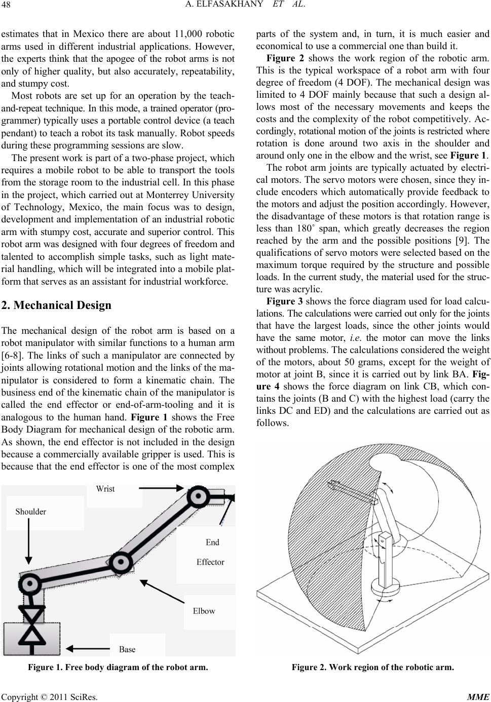 A. ELFASAKHANY ET AL. 48 estimates that in Mexico there are about 11,000 robotic arms used in different industrial applications. However, the experts think that the apogee of the robot arms is not only of higher quality, but also accurately, repeatability, and stumpy cost. Most robots are set up for an operation by the teach- and-repeat technique. In this mode, a trained operator (pro- grammer) typically uses a portable control device (a teach pendant) to teach a robot its task manually. Robot speeds during these programming sessions are slow. The present work is part of a two-phase project, which requires a mobile robot to be able to transport the tools from the storage room to the industrial cell. In this phase in the project, which carried out at Monterrey University of Technology, Mexico, the main focus was to design, development and implementation of an industrial robotic arm with stumpy cost, accurate and superior control. This robot arm was designed with four degrees of freedom and talented to accomplish simple tasks, such as light mate- rial handling, which will be integrated into a mobile plat- form that serves as an assistant for industrial workforce. 2. Mechanical Design The mechanical design of the robot arm is based on a robot manipulator with similar functions to a human arm [6-8]. The links of such a manipulator are connected by joints allowing rotational motion and the links of the ma- nipulator is considered to form a kinematic chain. The business end of the kinematic chain of the manipulator is called the end effector or end-of-arm-tooling and it is analogous to the human hand. Figure 1 shows the Free Body Diagram for mechanical design of the robotic arm. As shown, the end effector is not included in the design because a commercially available gripper is used. This is because that the end effector is one of the most complex Figure 1. Free body diagram of the robot arm. parts of the system and, in turn, it is much easier and economical to use a commercial one than build it. Figure 2 shows the work region of the robotic arm. This is the typical workspace of a robot arm with four degree of freedom (4 DOF). The mechanical design was limited to 4 DOF mainly because that such a design al- lows most of the necessary movements and keeps the costs and the complexity of the robot competitively. Ac- cordingly, rotational motion of the joints is restricted where rotation is done around two axis in the shoulder and around only one in the elbow and the wrist, see Figure 1. The robot arm joints are typically actuated by electri- cal motors. The servo motors were chosen, since they in- clude encoders which automatically provide feedback to the motors and adjust the position accordingly. However, the disadvantage of these motors is that rotation range is less than 180˚ span, which greatly decreases the region reached by the arm and the possible positions [9]. The qualifications of servo motors were selected based on the maximum torque required by the structure and possible loads. In the current study, the material used for the struc- ture was acrylic. Figure 3 shows the force diagram used for load calcu- lations. The calculations were carried out only for the joints that have the largest loads, since the other joints would have the same motor, i.e. the motor can move the links without problems. The calculations considered the weight of the motors, about 50 grams, except for the weight of motor at joint B, since it is carried out by link BA. Fig- ure 4 shows the force diagram on link CB, which con- tains the joints (B and C) with the highest load (carry the links DC and ED) and the calculations are carried out as follows. Figure 2. Work region of the robotic arm. Copyright © 2011 SciRes. MME 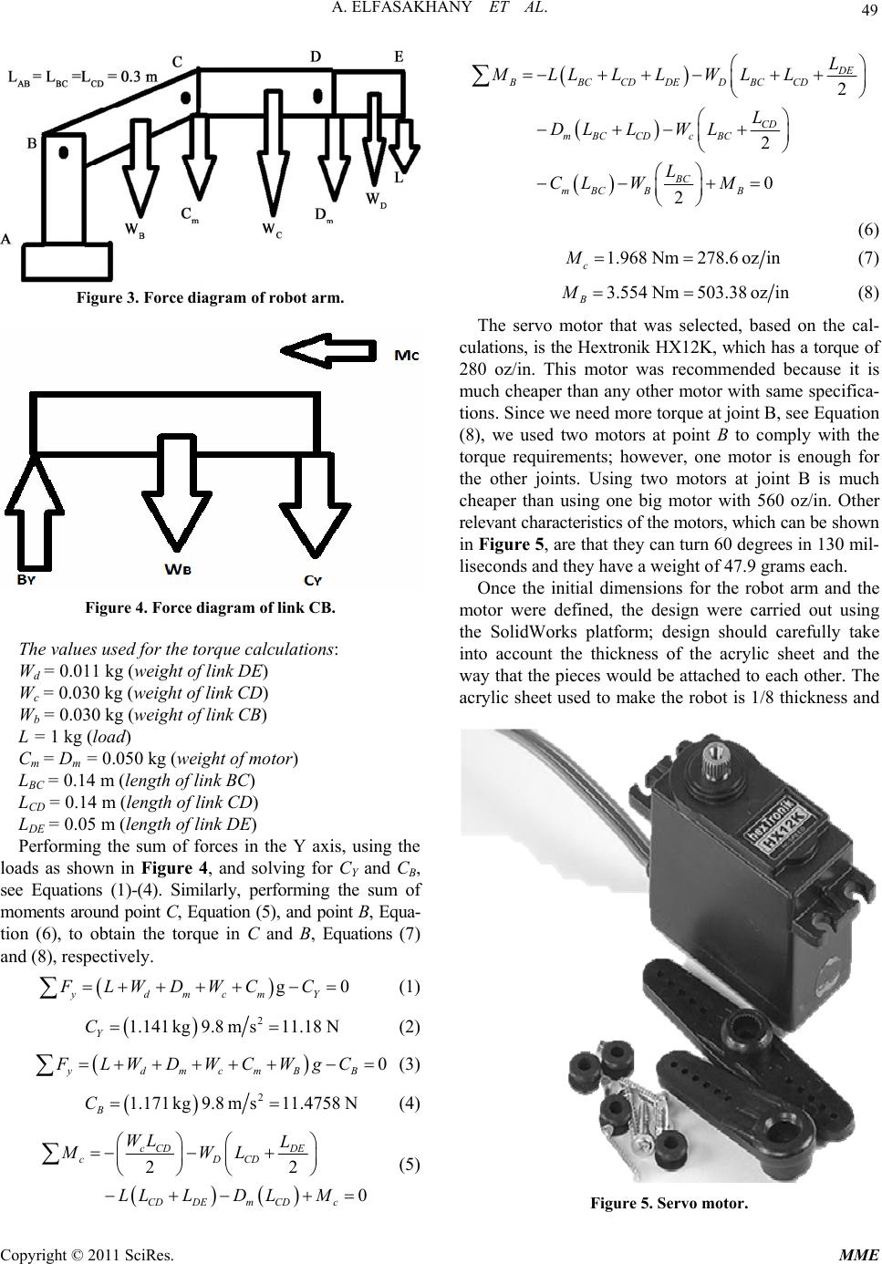 49 A. ELFASAKHANY ET AL. Figure 3. Force diagram of robot arm. Figure 4. Force diagram of link CB. The values used for the torque calculations: Wd = 0.011 kg (weight of link DE) Wc = 0.030 kg (weight of link CD) Wb = 0.030 kg (weight of link CB) L = 1 kg (load) Cm = Dm = 0.050 kg (weight of motor) LBC = 0.14 m (length of link BC) LCD = 0.14 m (length of link CD) LDE = 0.05 m (length of link DE) Performing the sum of forces in the Y axis, using the loads as shown in Figure 4, and solving for CY and CB, see Equations (1)-(4). Similarly, performing the sum of moments around point C, Equation (5), and point B, Equa- tion (6), to obtain the torque in C and B, Equations (7) and (8), respectively. g ydmcmY FLWDWC C 0 (1) 2 1.141kg9.8ms11.18N Y C (2) 0 ydmcmBB FLWDWCWgC (3) 2 1.171 kg9.8ms11.4758N B C (4) 22 0 cCD DE cDCD CDDEm CDc WL L MWL LLLD LM (5) 2 2 0 2 DE BBCCDDEDBCCD CD mBCCDc BC BC mBCBB L MLLLL WLL L DL LWL L CL WM (6) 1.968Nm278.6 ozin c M (7) 3.554Nm503.38 ozin B M (8) The servo motor that was selected, based on the cal- culations, is the Hextronik HX12K, which has a torque of 280 oz/in. This motor was recommended because it is much cheaper than any other motor with same specifica- tions. Since we need more torque at joint B, see Equation (8), we used two motors at point B to comply with the torque requirements; however, one motor is enough for the other joints. Using two motors at joint B is much cheaper than using one big motor with 560 oz/in. Other relevant characteristics of the motors, which can be shown in Figure 5, are that they can turn 60 degrees in 130 mil- liseconds and they have a weight of 47.9 grams each. Once the initial dimensions for the robot arm and the motor were defined, the design were carried out using the SolidWorks platform; design should carefully take into account the thickness of the acrylic sheet and the way that the pieces would be attached to each other. The acrylic sheet used to make the robot is 1/8 thickness and Figure 5. Servo motor. Copyright © 2011 SciRes. MME 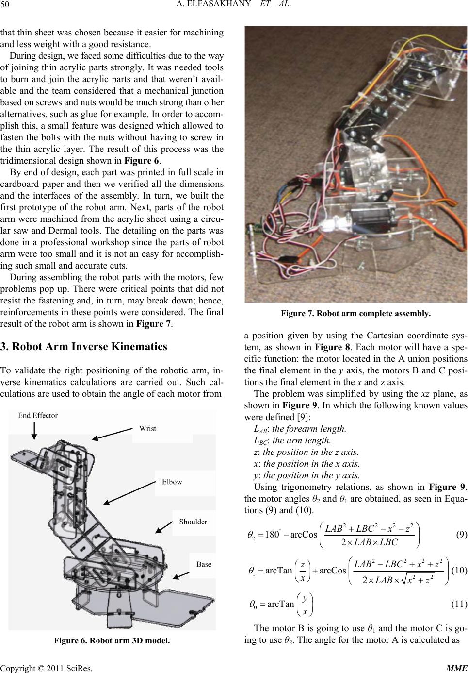 A. ELFASAKHANY ET AL. 50 that thin sheet was chosen because it easier for machining and less weight with a good resistance. During design, we faced some difficulties due to the way of joining thin acrylic parts strongly. It was needed tools to burn and join the acrylic parts and that weren’t avail- able and the team considered that a mechanical junction based on screws and nuts would be much strong than other alternatives, such as glue for example. In order to accom- plish this, a small feature was designed which allowed to fasten the bolts with the nuts without having to screw in the thin acrylic layer. The result of this process was the tridimensional design shown in Fi gu re 6. By end of design, each part was printed in full scale in cardboard paper and then we verified all the dimensions and the interfaces of the assembly. In turn, we built the first prototype of the robot arm. Next, parts of the robot arm were machined from the acrylic sheet using a circu- lar saw and Dermal tools. The detailing on the parts was done in a professional workshop since the parts of robot arm were too small and it is not an easy for accomplish- ing such small and accurate cuts. During assembling the robot parts with the motors, few problems pop up. There were critical points that did not resist the fastening and, in turn, may break down; hence, reinforcements in these points were considered. The final result of the robot arm is shown in Figure 7. 3. Robot Arm Inverse Kinematics To validate the right positioning of the robotic arm, in- verse kinematics calculations are carried out. Such cal- culations are used to obtain the angle of each motor from Figure 6. Robot arm 3D model. Figure 7. Robot arm complete assembly. a position given by using the Cartesian coordinate sys- tem, as shown in Figure 8. Each motor will have a spe- cific function: the motor located in the A union positions the final element in the y axis, the motors B and C posi- tions the final element in the x and z axis. The problem was simplified by using the xz plane, as shown in Figure 9. In which the following known values were defined [9]: LAB: the forearm length. LBC: the arm length. z: the position in the z axis. x: the position in the x axis. y: the position in the y axis. Using trigonometry relations, as shown in Figure 9, the motor angles θ2 and θ1 are obtained, as seen in Equa- tions (9) and (10). 222 2180 arcCos2 LAB LBCx z LAB LBC 2 (9) 222 122 arcTan arcCos 2 zLABLBCx xLABx z 2 z (10) 0arcTan y (11) The motor B is going to use θ1 and the motor C is go- ing to use θ2. The angle for the motor A is calculated as Copyright © 2011 SciRes. MME 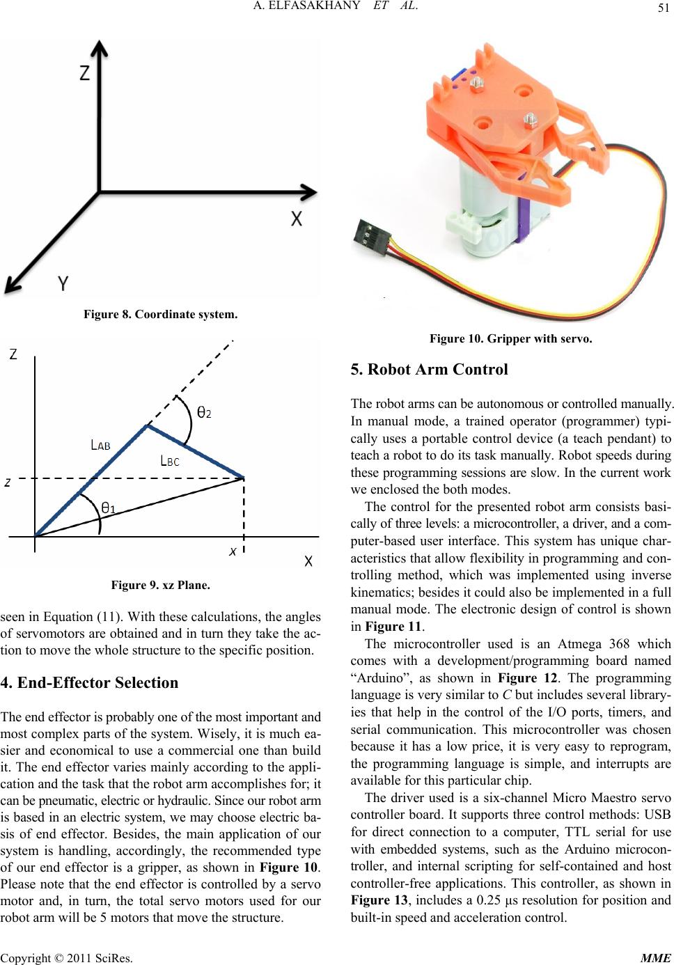 51 A. ELFASAKHANY ET AL. Figure 8. Coordinate system. Figure 9. xz Plane. seen in Equation (11). With these calculations, the angles of servomotors are obtained and in turn they take the ac- tion to move the whole structure to the specific position. 4. End-Effector Selection The end effector is probably one of the most important and most complex parts of the system. Wisely, it is much ea- sier and economical to use a commercial one than build it. The end effector varies mainly according to the appli- cation and the task that the robot arm accomplishes for; it can be pneumatic, electric or hydraulic. Since our robot arm is based in an electric system, we may choose electric ba- sis of end effector. Besides, the main application of our system is handling, accordingly, the recommended type of our end effector is a gripper, as shown in Figure 10. Please note that the end effector is controlled by a servo motor and, in turn, the total servo motors used for our robot arm will be 5 motors that move the structure. Figure 10. Grip per with ser v o . 5. Robot Arm Control The robot arms can be autonomous or controlled manually. In manual mode, a trained operator (programmer) typi- cally uses a portable control device (a teach pendant) to teach a robot to do its task manually. Robot speeds during these programming sessions are slow. In the current work we enclosed the both modes. The control for the presented robot arm consists basi- cally of three levels: a microcontroller, a driver, and a com- puter-based user interface. This system has unique char- acteristics that allow flexibility in programming and con- trolling method, which was implemented using inverse kinematics; besides it could also be implemented in a full manual mode. The electronic design of control is shown in Figure 11. The microcontroller used is an Atmega 368 which comes with a development/programming board named “Arduino”, as shown in Figure 12. The programming language is very similar to C but includes several library- ies that help in the control of the I/O ports, timers, and serial communication. This microcontroller was chosen because it has a low price, it is very easy to reprogram, the programming language is simple, and interrupts are available for this particular chip. The driver used is a six-channel Micro Maestro servo controller board. It supports three control methods: USB for direct connection to a computer, TTL serial for use with embedded systems, such as the Arduino microcon- troller, and internal scripting for self-contained and host controller-free applications. This controller, as shown in Figure 13, includes a 0.25 μs resolution for position and built-in speed and acceleration control. Copyright © 2011 SciRes. MME 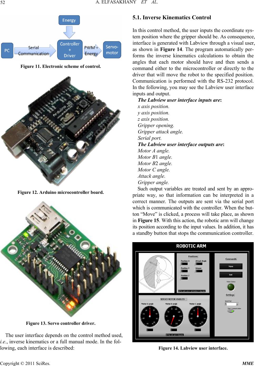 A. ELFASAKHANY ET AL. 52 Figure 11. Electronic scheme of control. Figure 12. Arduino microcontroller board. Figure 13. Servo controller driver. The user interface depends on the control method used, i.e., inverse kinematics or a full manual mode. In the fol- lowing, each interface is described: 5.1. Inverse Kinematics Control In this control method, the user inputs the coordinate sys- tem position where the gripper should be. As consequence, interface is generated with Labview through a visual user, as shown in Figure 14. The program automatically per- forms the inverse kinematics calculations to obtain the angles that each motor should have and then sends a command either to the microcontroller or directly to the driver that will move the robot to the specified position. Communication is performed with the RS-232 protocol. In the following, you may see the Labview user interface inputs and output. The Labview user interface inputs are: x axis position. y axis position. z axis position. Gripper opening. Gripper attack angle. Serial port. The Labview user interface outputs are: Motor A angle. Motor B1 angle. Motor B2 angle. Motor C angle. Attack angle. Gripper angle. Such output variables are treated and sent by an appro- priate way, so that information can be interpreted in a correct manner. The outputs are sent via the serial port which is communicated with the controller. When the but- ton “Move” is clicked, a process will take place, as shown in Figure 15. With this action, the robotic arm will change its position according to the input values. In addition, it has a standby button that stops the communication controller. Figure 14. Labview user interface. Copyright © 2011 SciRes. MME 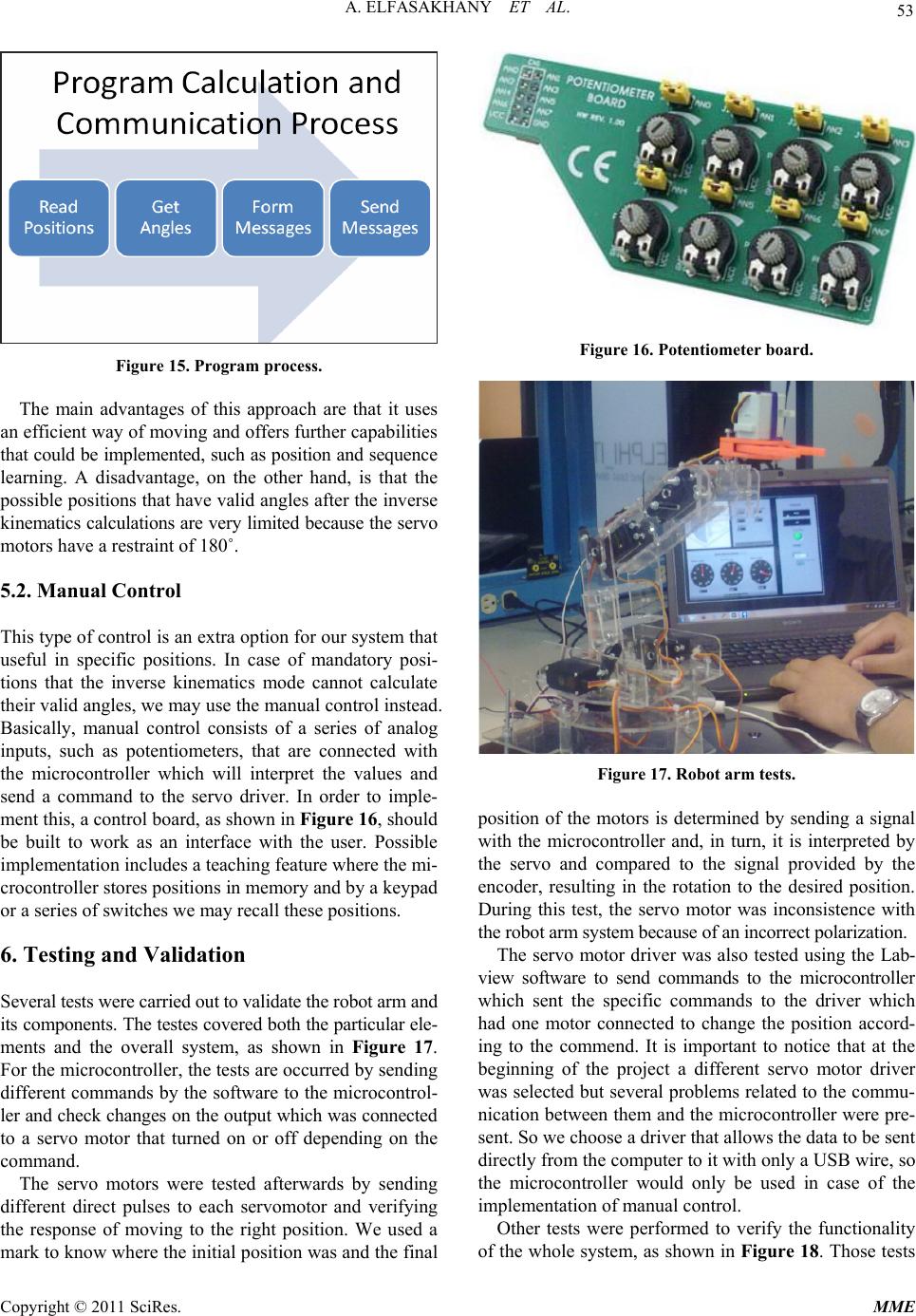 53 A. ELFASAKHANY ET AL. Figure 15. Program process. The main advantages of this approach are that it uses an efficient way of moving and offers further capabilities that could be implemented, such as position and sequence learning. A disadvantage, on the other hand, is that the possible positions that have valid angles after the inverse kinematics calculations are very limited because the servo motors have a restraint of 180˚. 5.2. Manual Control This type of control is an extra option for our system that useful in specific positions. In case of mandatory posi- tions that the inverse kinematics mode cannot calculate their valid angles, we may use the manual control instead. Basically, manual control consists of a series of analog inputs, such as potentiometers, that are connected with the microcontroller which will interpret the values and send a command to the servo driver. In order to imple- ment this, a control board, as shown in Figure 16, should be built to work as an interface with the user. Possible implementation includes a teaching feature where the mi- crocontroller stores positions in memory and by a keypad or a series of switches we may recall these positions. 6. Testing and Validation Several tests were carried out to validate the robot arm and its components. The testes covered both the particular ele- ments and the overall system, as shown in Figure 17. For the microcontroller, the tests are occurred by sending different commands by the software to the microcontrol- ler and check changes on the output which was connected to a servo motor that turned on or off depending on the command. The servo motors were tested afterwards by sending different direct pulses to each servomotor and verifying the response of moving to the right position. We used a mark to know where the initial position was and the final Figure 16. Potentiometer board. Figure 17. Robot arm tests. position of the motors is determined by sending a signal with the microcontroller and, in turn, it is interpreted by the servo and compared to the signal provided by the encoder, resulting in the rotation to the desired position. During this test, the servo motor was inconsistence with the robot arm system because of an incorrect polarization. The servo motor driver was also tested using the Lab- view software to send commands to the microcontroller which sent the specific commands to the driver which had one motor connected to change the position accord- ing to the commend. It is important to notice that at the beginning of the project a different servo motor driver was selected but several problems related to the commu- nication between them and the microcontroller were pre- sent. So we choose a driver that allows the data to be sent directly from the computer to it with only a USB wire, so the microcontroller would only be used in case of the implementation of manual control. Other tests were performed to verify the functionality of the whole system, as shown in Figure 18. Those tests Copyright © 2011 SciRes. MME  A. ELFASAKHANY ET AL. 54 Figure 18. Robot arm in action. were occurred by introducing a specific position in the Labview interface and measuring the distance between a reference point and the final point in order to verify: the correct transformation from inverse to direct kinematics, the relationship between the specified angles and the ro- tation of the motors. Testing and validation of the robot arm is one of the tasks that require elongated time because several iterations are needed. During our tests, many problems arise as: wrong angle calculations, wrong calibration of the mo- tors, problems with the physical angle and position mea- surements, and one of the servo motors burned because of an overload that wasn’t expected. 7. Results and Discussions Results from the robot arm at different operating condi- tions are presented as follows: 7.1. Servo Motors Movement Range The limits of the servo motors were obtained since speci- fication of this type of motors contains that it has less than a 180 degree span. The real range for all motors was found to be in the range 125 - 142 degrees, as shown in Table 1. This clearly demonstrated that real operation of robot arm is different from the stander case. Table 1. Motor angle ranges. Motor Angle Range Motor A 130˚ Motor B1 135˚ Motor B2 140˚ Motor C 142˚ Motor Attack Angle 125˚ 7.2. Current Consumption The current consumption depends on the load and the type of motion of the robotic arm. In the current study, there are 4 levels of current consumptions: Low (from 0 to 200 mA). This consumption takes place when the robot is at rest (not motion case). • Normal (from 200 to 500 mA). This happened when the robot arm is moving with capability to go to the tar- get without needs of great torque. • High (from 500 mA to 900 mA). This range is rea- ched at the beginning of carrying loads. By overcoming the initial moment of inertia for loads, the normal range takes a place. Over current (more than 900 mA). The load is too hea- vy and the motor cannot move at all. For being under this condition for more than one minute, the motor will burn, i.e. it is not possible to be used any more. 7.3. Maximum Load These results were obtained using different weights; a bag of corn was used with a scale to determine bag’ weight. Results carried out by using the robot arm to pick up the bag and move it to specific positions. Table 2 presents the current consumption at different weights of bag of corn. From Table 2, it can be seen that the robot can move without problems at loads lower than 50 grams. At loads 60 grams, the robot arm start having difficulties and after passing 80 grams severe condition occurred where ire- versible damage could be happened in motors. 7.4. Final Position Results show the precision of the robot arm to move dif- ferent weight (<50 grams) is presented in Table 3. As shown, the robot arm is able to perform the movement to the position specified. However, this movement is not smooth and sometimes the motors do not have enough force, especially when the load is heavy. In addition, some problems may appear due to synchronizing the two bottom motors. The steps of the two motors were not coincidental and that causes tension in the acrylic parts, which in case of being too much will break the parts. Copyright © 2011 SciRes. MME 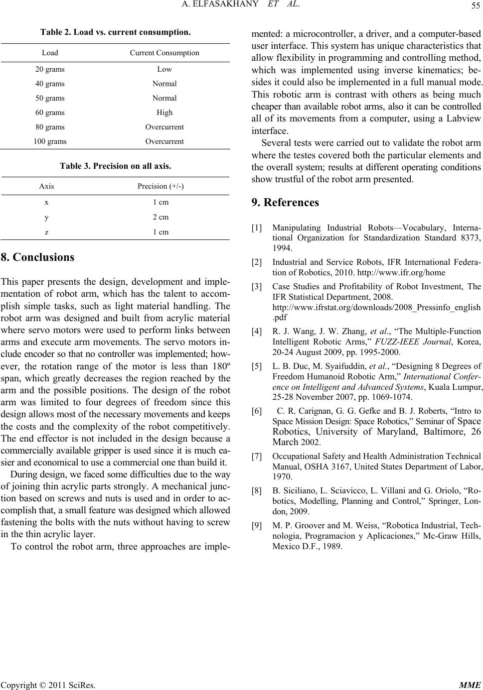 A. ELFASAKHANY ET AL. Copyright © 2011 SciRes. MME 55 Table 2. Load vs. current consumption. Load Current Consumption 20 grams Low 40 grams Normal 50 grams Normal 60 grams High 80 grams Overcurrent 100 grams Overcurrent Table 3. Precision on all axis. Axis Precision (+/-) x 1 cm y 2 cm z 1 cm 8. Conclusions This paper presents the design, development and imple- mentation of robot arm, which has the talent to accom- plish simple tasks, such as light material handling. The robot arm was designed and built from acrylic material where servo motors were used to perform links between arms and execute arm movements. The servo motors in- clude encoder so that no controller was implemented; how- ever, the rotation range of the motor is less than 180º span, which greatly decreases the region reached by the arm and the possible positions. The design of the robot arm was limited to four degrees of freedom since this design allows most of the necessary movements and keeps the costs and the complexity of the robot competitively. The end effector is not included in the design because a commercially available gripper is used since it is much ea- sier and economical to use a commercial one than build it. During design, we faced some difficulties due to the way of joining thin acrylic parts strongly. A mechanical junc- tion based on screws and nuts is used and in order to ac- complish that, a small feature was designed which allowed fastening the bolts with the nuts without having to screw in the thin acrylic layer. To control the robot arm, three approaches are imple- mented: a microcontroller, a driver, and a computer-based user interface. This system has unique characteristics that allow flexibility in programming and controlling method, which was implemented using inverse kinematics; be- sides it could also be implemented in a full manual mode. This robotic arm is contrast with others as being much cheaper than available robot arms, also it can be controlled all of its movements from a computer, using a Labview interface. Several tests were carried out to validate the robot arm where the testes covered both the particular elements and the overall system; results at different operating conditions show trustful of the robot arm presented. 9. References [1] Manipulating Industrial Robots—Vocabulary, Interna- tional Organization for Standardization Standard 8373, 1994. [2] Industrial and Service Robots, IFR International Federa- tion of Robotics, 2010. http://www.ifr.org/home [3] Case Studies and Profitability of Robot Investment, The IFR Statistical Department, 2008. http://www.ifrstat.org/downloads/2008_Pressinfo_english .pdf [4] R. J. Wang, J. W. Zhang, et al., “The Multiple-Function Intelligent Robotic Arms,” FUZZ-IEEE Journal, Korea, 20-24 August 2009, pp. 1995-2000. [5] L. B. Duc, M. Syaifuddin, et al., “Designing 8 Degrees of Freedom Humanoid Robotic Arm,” International Confer- ence on Intelligent and Advanced Systems, Kuala Lumpur, 25-28 November 2007, pp. 1069-1074. [6] C. R. Carignan, G. G. Gefke and B. J. Roberts, “Intro to Space Mission Design: Space Robotics,” Seminar of Space Robotics, University of Maryland, Baltimore, 26 March 2002. [7] Occupational Safety and Health Administration Technical Manual, OSHA 3167, United States Department of Labor, 1970. [8] B. Siciliano, L. Sciavicco, L. Villani and G. Oriolo, “Ro- botics, Modelling, Planning and Control,” Springer, Lon- don, 2009. [9] M. P. Groover and M. Weiss, “Robotica Industrial, Tech- nologia, Programacion y Aplicaciones,” Mc-Graw Hills, Mexico D.F., 1989.
|