Y. LI ET AL. 39
kinematics and dynamics. In o rder to realize dynamic mo-
deling of the PWA system, the kinematics and dynamics
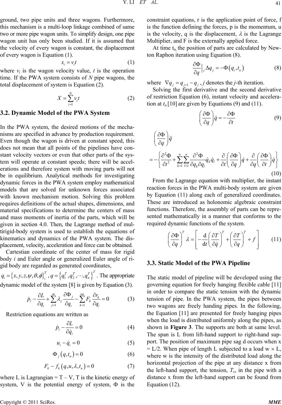
models of the system are built in terms of the theory of
machines and mechanisms [6,7]. The principles of me-
chanics [8] can be used to static modeling mechanical
system. So, the solved kinematics and dynamics of ma-
chinery can yield equations for dynamic-motion, static-
force and dynamic-force analysis [9].
However, for the dynamic simulation of the PWA
system two key factors differ from the GAP system. One
of the key factors is system kinematics modeling. The
pipelines exhibit highly geometrically nonlinear behavior.
They are very flexible and undergo large displacements
before attaining their equilibrium configuration. Due to
this inherently nonlinear behavior, the flexible pipelines
do not fit the assumption of rigidity. They usually have
no effect on the kinematics of the system but do play a
role in supplying forces. The pipelines of the system are
usually ignored during kinematic analysis, and their force
effects are introduced during dynamic simulation [7].
Another of the key factors is pipeline modeling. The PWA
system is made up of linkages of wagons connected by
rubber pipelines. The rubber pipelines are used for trans-
mitting forces or displacements be tween wagons. Because
transmission paths are often convoluted, and the pipe per-
formance is dependent on phenomenon such as friction
and stretching, it is difficult to model pipelines using stan-
dard tools available in most mechanical system simula-
tion packages. The way to model fixable pipeline in AD-
AMS is to discretize th e pipe i n to seg ments. Th e seg ments
are then attached with a constraint.
In this work, the theoretical modeling and virtual pro-
totype simulation of the PWA have been focused on.
Using the virtual model developed in this work, the fol-
lowing work has been carried out: 1) realization of dy-
namic simulation; 2) creation of 3-D solid visualization
models with 3-D motion for the PWA system; 3) de-
termination of important engineering data, such as maxi-
mum force necessary to drive the PWA machinery using
reality and virtual prototypes; 4) analysis of the distri-
bution of tension along pipe and comparison of static
tension with dynamic tension.
2. Concetual Design of the PWA System
The PWA system will facilitate the conveyance of oil
sands slurry to joint a fixed pipeline or existing hydro-
transport train (HTP). This system has been designed and
developed to withstand the oil sands mechanical and che-
mical characteristics and handle oil sands slurry rate or
flow rate of 6100 tph. It must accommodate production
face advance of 60 m/day or 400 m/week w ith a robu st sys-
tem components interfaces. The slurry component sizes
must be a fraction of minus 80mm with a specific gravity
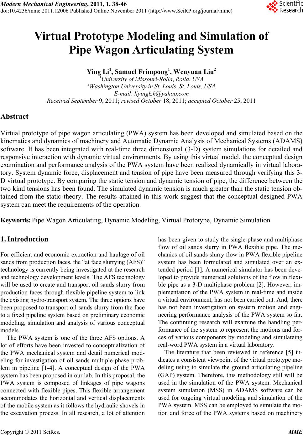
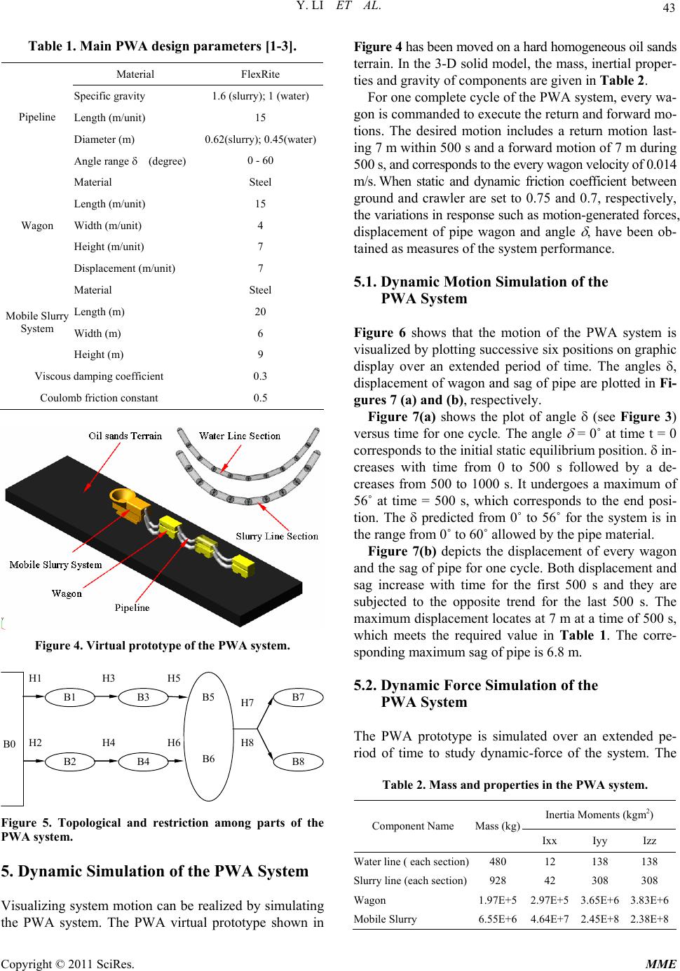
of 1.6. The PWA concept is illu strated in Figure 1(a). This
system will work with a shovel, mobile slurry system with
slurry pump system, PWA system and fixed pipeline sys-
tem. The PWA system consists of linkages of wagons con-
nected by FlexRite flexible pipelines. In this combined
system the shovel excavates and feeds dry oil sands lumps
into the mobile slurry system and with the addition of hot
water into the system, oil sands are slurried. The result-
ing oil sands slurry is then pumped through the PWA
system to join the fixed pipeline or existing HTP.
Figure 1(b) indicates that the PWA system will consis t
of a series of rigid truss frames on castors and will be al-
lowed to swivel relative to each other. Each frame will
support concentrated 24” diameter slurry and 18” diamete r
fresh water lines. A flexible pipeline assembly is required to
allow flow of both slurry and fresh water while permitting
the position changes between adjacent trusses. FlexRite
pipes are more flexible than conventional steel pipes and
provide maximum bending with smooth flow of materials.
The flow across the FlexRite pipeline can change in any
direction due to the flexible nature of the pipeline system.
The flexible pipe can bend to a maximum angle of 60˚.
Two types of particles or mixtures impingement can oc-
cur including straight horizontal flexible pipe and bend
(from 0˚ to 60˚ deflection) flexible pipe.
A mining sequence can be established for a movement
of a shovel within the pit. The mobile slurry system is
designed to follow the shov el as it traverses the pit. Dur-
ing this operation, the pipe will move as they follow the
movements of the shovel as illustrated in Figure 1(a). To
accommodate a shovel advance, the PWA arms will be
added at various advance rates as illustrated . As the mine
face advances the stretching PWA will follow shovel.
The PWA movement will be automated and robotized
through computer vision systems. In this case, the PWA
can accumulate or un-accumulate allowing the effective
working envelope between the mine face and fixed pipe-
line to be varied.
3. Theoretical Models of the PWA System
3.1. Motion Model of the PWA Wagon
The requirement by the PWA system is that of causing
an output member to move from one position to another.
In analyzing motion, the first and most basic problem
encountered is that of defining and dealing with the con-
cepts of position and displacement. Since motion can be
thought of as a time series of displacements between suc-
cessive positions, it is important to analyze exactly the
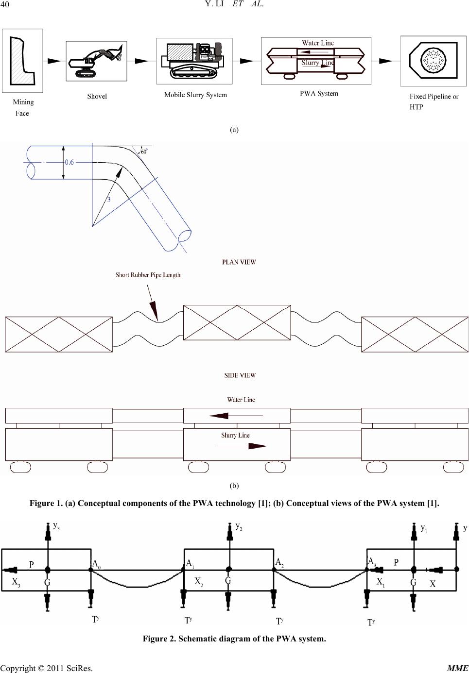
positions of mechanism in the PWA system. Figure 2 is
a schematic drawing of the PWA system including the
Copyright © 2011 SciRes. MME