Paper Menu >>
Journal Menu >>
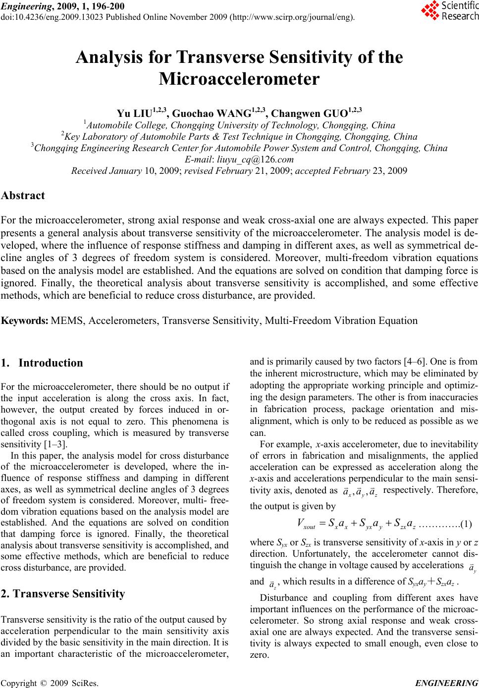 Engineering, 2009, 1, 196-200 doi:10.4236/eng.2009.13023 Published Online November 2009 (http://www.scirp.org/journal/eng). Copyright © 2009 SciRes. ENGINEERING Analysis for Transverse Sensitivity of the Microaccelerometer Yu LIU1,2,3, Guochao WANG1,2,3, Changwen GUO1,2,3 1Automobile College, Chongqing University of Technology, Chongqing, China 2Key Laboratory of Automobile Parts & Test Technique in Chongqing, Chongqing, China 3Chongqing Engineering Research Center for Automobile Power System and Control, Chongqing, China E-mail: liuyu_cq@126.com Received January 10, 2009; revised February 21, 2009; accepted February 23, 2009 Abstract For the microaccelerometer, strong axial response and weak cross-axial one are always expected. This paper presents a general analysis about transverse sensitivity of the microaccelerometer. The analysis model is de- veloped, where the influence of response stiffness and damping in different axes, as well as symmetrical de- cline angles of 3 degrees of freedom system is considered. Moreover, multi-freedom vibration equations based on the analysis model are established. And the equations are solved on condition that damping force is ignored. Finally, the theoretical analysis about transverse sensitivity is accomplished, and some effective methods, which are beneficial to reduce cross disturbance, are provided. Keywords: MEMS, Accelerometers, Transverse Sensitivity, Multi-Freedom Vibration Equation 1. Introduction For the microaccelerometer, there should be no output if the input acceleration is along the cross axis. In fact, however, the output created by forces induced in or- thogonal axis is not equal to zero. This phenomena is called cross coupling, which is measured by transverse sensitivity [1–3]. In this paper, the analysis model for cross disturbance of the microaccelerometer is developed, where the in- fluence of response stiffness and damping in different axes, as well as symmetrical decline angles of 3 degrees of freedom system is considered. Moreover, multi- free- dom vibration equations based on the analysis model are established. And the equations are solved on condition that damping force is ignored. Finally, the theoretical analysis about transverse sensitivity is accomplished, and some effective methods, which are beneficial to reduce cross disturbance, are provided. 2. Transverse Sensitivity Transverse sensitivity is the ratio of the output caused by acceleration perpendicular to the main sensitivity axis divided by the basic sensitivity in the main direction. It is an important characteristic of the microaccelerometer, and is primarily caused by two factors [4–6]. One is from the inherent microstructure, which may be eliminated by adopting the appropriate working principle and optimiz- ing the design parameters. The other is from inaccuracies in fabrication process, package orientation and mis- alignment, which is only to be reduced as possible as we can. For example, x-axis accelerometer, due to inevitability of errors in fabrication and misalignments, the applied acceleration can be expressed as acceleration along the x-axis and accelerations perpendicular to the main sensi- tivity axis, denoted as ,, x yz aaa respectively. Therefore, the output is given by zzxyyxxxxout aSaSaSV ………….(1) where Syx or Szx is transverse sensitivity of x-axis in y or z direction. Unfortunately, the accelerometer cannot dis- tinguish the change in voltage caused by accelerations y a and z a , which results in a difference of Syxay+Szxaz . Disturbance and coupling from different axes have important influences on the performance of the microac- celerometer. So strong axial response and weak cross- axial one are always expected. And the transverse sensi- tivity is always expected to small enough, even close to zero. 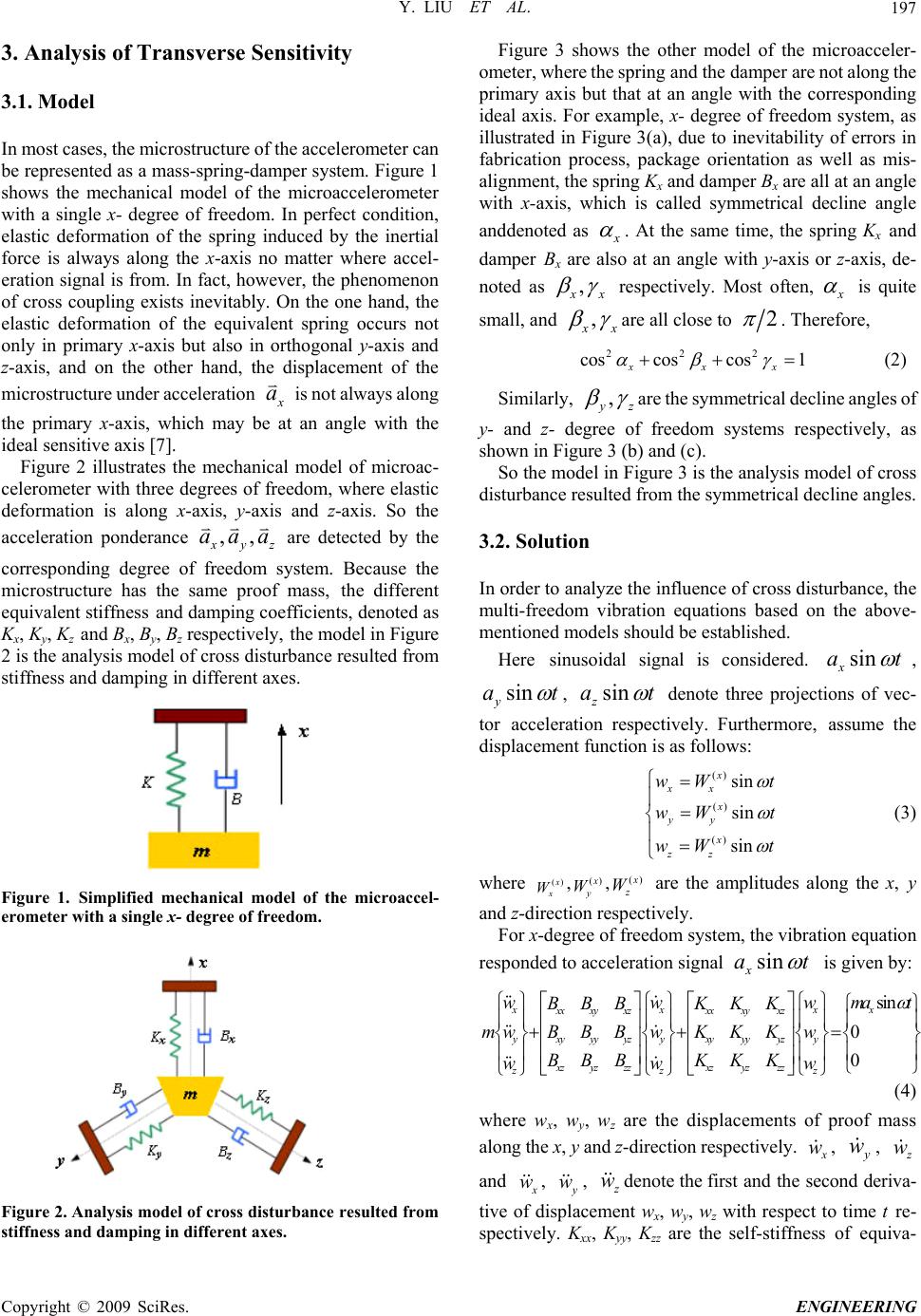 Y. LIU ET AL.197 , the microstructure of the accelerometer can e represented as a mass-spring-damper system. Figure 1 3. Analysis of Transverse Sensitivity 3.1. Model In most cases b shows the mechanical model of the microaccelerometer with a single x- degree of freedom. In perfect condition, elastic deformation of the spring induced by the inertial force is always along the x-axis no matter where accel- eration signal is from. In fact, however, the phenomenon of cross coupling exists inevitably. On the one hand, the elastic deformation of the equivalent spring occurs not only in primary x-axis but also in orthogonal y-axis and z-axis, and on the other hand, the displacement of the microstructure under acceleration x a is not always along the primary x-axis, which may be at an angle with the ideal sensitive axis [7]. Figure 2 illustrates the mechanical model of microac- celerometer with three degrees of freedom, where elastic deformation is along x-axis, y-axis and z-axis. So the acceleration ponderance ,, x yz aaa are detected by the corresponding degree of system. Because the microstructure has the sa mass, the different equivalent stiffness and damping coefficients, denoted as Kx, Ky, Kz and Bx, By, Bz respectively, the model in Figure 2 is the analysis model of cross disturbance resulted from stiffness and damping in different axes. freedom me proof Figure 1. Simplified mechanical model of the microaccel- erometer with a single x- degree of freedom. Figure 2. Analysis model of cross disturbanceesulted from stiffness and damping in different axes. are not along the pr r Figure 3 shows the other model of the microacceler- ometer, where the spring and the damper imary axis but that at an angle with the corresponding ideal axis. For example, x- degree of freedom system, as illustrated in Figure 3(a), due to inevitability of errors in fabrication process, package orientation as well as mis- alignment, the spring Kx and damper Bx are all at an angle with x-axis, which is called symmetrical decline angle anddenoted as x . At the same time, the spring Kx and damper Bx are also at an angle with y-axis or z-axis, de- noted as , x x respectively. Most often, x is quite small, and , x x are all close to 2 . Therre, cos co1 xx efo 222 coss x (2) Similarly, , yz are the symmetrical de y- and gree of freedom syste shre 3 (b mmetrical decline angles. ze the influence of cross disturbance, the ulti-freedom vibration equations based on the above- cline angles of z- dems respectively, as own in Figu) and (c). So the model in Figure 3 is the analysis model of cross disturbance resulted from the sy 3.2. Solution In order to analy m mentioned models should be established. Here sinusoidal signal is considered. sin x at , asin yt , sin z at denote three projecti- ation Furthermore, assume the ntis as follows: () () sin x xx x wW t ons of vec tor accelerrespectively. displaceme function () sin sin yy x zz wW t wW t (3) where ()x x W,() x y W,() x z W are the amplitudes along the x, y irection respectiv -deee fre al and z-dely. For xgrofedom system, the vibration equation responded to acceleration sign sinat x is given by: si n xx xx xx xy xzxx ww mat BBB KK 0 0 xy xz yxyyyyz yxyyy yzy xz yz zzxzyzzz zz z w K mw BBBw KKKw BBB KKK ww w (4) where wx, wy, wz are the displacements o along the x, y and z-direction respectively. f proof mass x w , w , y z w and x w , y w , z w denote the first and the seconri tive ofce wx, wy, wz with respect to time t re- spect lyxx, y, Kzz are the self-stiffness of equiva- d deva- displament ive. KKy Copyright © 2009 SciRes. ENGINEERING 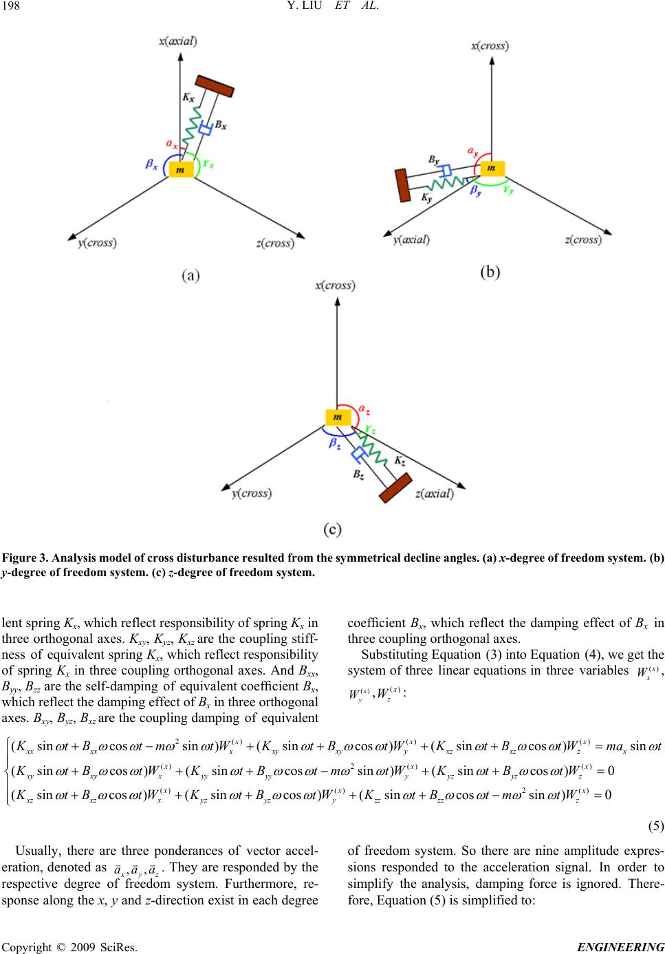 Y. LIU ET AL. 198 Figure 3. Analysis model of cross disturbance resulted from the symmetrical decline angles. (a) x-degree of freedom syem. (b) lent spring Kx, which reflect responsibility of spring Kx in coefficient Bx, which reflect the damping effect of Bx in st y-degree of freedom system. (c) z-degree of freedom system. three orthogonal axes. Kxy, Kyz, Kxz are the coupling stiff- ness of equivalent spring Kx, which reflect responsibility of spring Kx in three coupling orthogonal axes. And Bxx, Byy, Bzz are the self-damping of equivalent coefficient Bx, which reflect the damping effect of Bx in three orthogonal axes. Bxy, Byz, Bxz are the coupling damping of equivalent three coupling orthogonal axes. Substituting Equation (3) into Equation (4), we get the system of three linear equations in three variables () x x W, () x y W,() x z W: 2() (sincossin )(sin x() () ()2 ()() cos )(sincos )sin (sincos )(sincossin )(sincos )0 (sincos x xxxxx xyxyy xzxzzx xx xyxyx yyyyy yzyzz xz xz x x K tBtmtW KtBtW KtBtWmat KtBtWKtBtmtWKtBtW KtB ()()2 () )(sincos)(sincossin )0 xx xyzyzy zzzzz tWKt BtWKtBtmtW x (5) Usually, there are three ponderances of vector accel- eration, denoted as ,, x yz aaa . They are responded by the respective degree o system. Furthermore, re- sponse along the x, y and z-direction exist in each degree sions responded to the acceleration signal. In order to simplify the analysis, damping force is ignored. There- fore, Equation (5) is simplified to: f freedom of freedom system. So there are nine amplitude expres- C opyright © 2009 SciRes. ENGINEERING 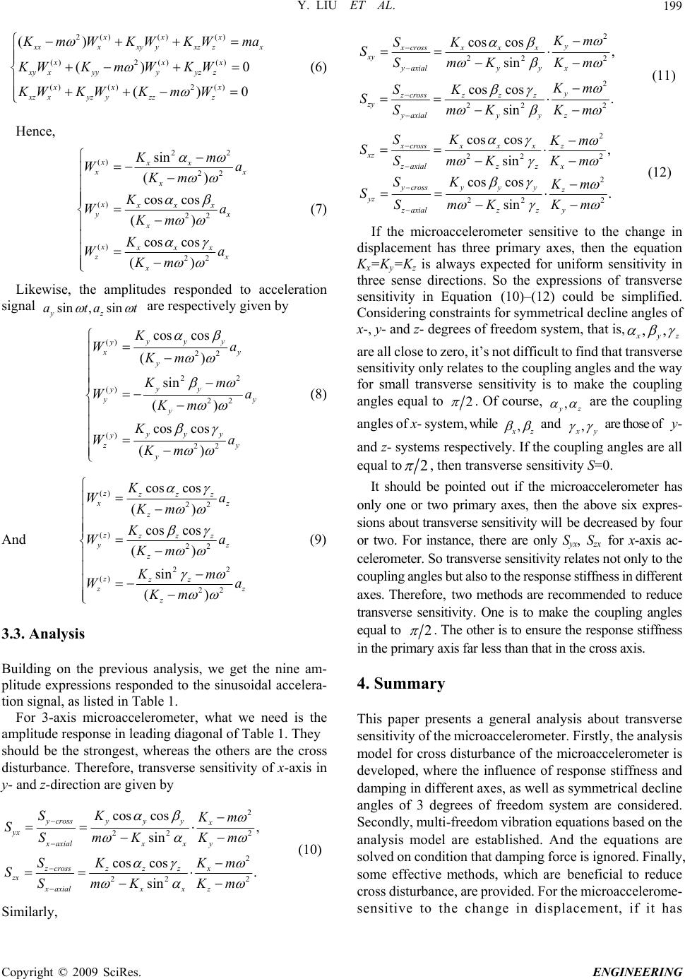 Y. LIU ET AL.199 0 0 2() () () ()2 () () () xxx () ()()2 () () x xxxyyxzzx xxx xy xyyyyz z xx x xz xyz yzzz K mW KW KWma KWKm WK W KWKWKm W (6) Hence, 22 () 22 () 22 () 22 sin () cos cos () cos cos () xxx x x x xxxx yx x xxxx zx x Km Wa Km K Wa Km K Wa Km (7) Likewise, the amplitudes responded to acceleration signal t sin, sin yz ata are respectively given by () 22 cos cos () yyy y y Ka Km 22 () 22 () 22 sin () cos cos () x y yy y yy y yy y y zy y W Km Wa Km K Wa Km (8 ) And () 22 () 22 22 () 22 cos cos () cos cos () sin () zzzz xz z zzzz yz z zzz z z z K Wa Km K Wa Km Km W Km a (9) 3.3. Analysis previous analysis, we get the nine am- ons responded to the sinusoidal accelera- Building on the litude expressip tion signal, as listed in Table 1. For 3-axis microaccelerometer, what we need is the amplitude response in leading diagonal of Table 1. They should be the strongest, whereas the others are the cross disturbance. Therefore, transverse sensitivity of x-axis in y- and z-direction are given by 2 22 cos cos sin ycrossyyy x yx SK Km SSmK 2 22 2 22 cos cos, sin cos cos. sin y xcross x x x xy yaxial yyx y zcross zzz zy yaxial yyz Km 2 2 K SSmK Km Km SK SSmK Km S (11) 2 22 2 22 cos cos, sin cos cos. sin xcrossxxxz xz zaxialzz x ycrossyyy z yz zaxialzz y SK Km SSmKKm SK Km SSmK Km 2 2 (12) If the microaccelerometer sensitive to the change in displacement has three primary axes, then the equation Kx=Ky=Kz is always expected for uniform sensitivity in three sense directions. So the expressions of transverse sensitivity in Equation (10)–(12) could be simplified. Considering constraints for symmetrical decline angles of x-, y- and z- degrees of freedom system, that is,,, x yz are all close to zero, it’s not difficult to find that t sensitivity only relates to the coupling angles and the way for small transverse sensitivity is to make the coupling angles equal to ransverse 2 . Of course, , yz are the coupling angles of x- systehile , m, w x z and , x y are those of y- and z- systems respectivelhe co angles are all equal to y. If tupling 2 , then transverse sensitivity S=0. It shoube pointed out if the microaccelerld on ometer has ly one or two primary axes, then the above six expres- sions about transverse sensitivity will be decreased by four or two. For instance, there are only Syx, Szx for x-axis ac- celerometer. So transverse sensitivity relates not only to the coupling angles but also to the response stiffness in different axes. Therefore, two methods are recommended to reduce transverse sensitivity. One is to make the coupling angles equal to 2 . The other is to ensure the response stiffness in the prim axis far less than that in the cross axis. ary 4. Summary ents a general analysis about transverse This paper pres 2 2 222 , cos cos . sin xa xialxx y zcross x zzz zx xaxial xxz Km SKm K SSmKKm sensitivity of the microaccelerometer. Firstly, the analysis model for cross disturbance of the microaccelerometer is developed, where the influence of response stiffness and damping in different axes, as well as symmetrical decline angles of 3 degrees of freedom system are considered. Secondly, multi-freedom vibration equations based on the analysis model are established. And the equations are solved on condition that damping force is ignored. Finally, some effective methods, which are beneficial to reduce cross disturbance, are provided. For the microaccelerome- (10) Similarly, sensitive to the change in displacement, if it has Copyright © 2009 SciRes. ENGINEERING  Y. LIU ET AL. 200 Table 1. Amplitude responded to the sinusoidal acceleration signal. Amplitude Acceleration x-direction y-direction z-direction sin x at 22 22 sin () xx x x Km a Km 22 cos cos () xxx x x Ka Km 22 cos cos () xxx x x Ka Km sin y at 22 cos cos () yyy y y Ka Km 22 22 sin () yy y y Km a Km 22 cos cos () yyy y y Ka Km sin z at 22 cos cos () zzz z z Ka Km 22 cos cos () zzz z z Ka Km 22 22 sin () zz z z Km a Km three primary axes, then transverse sensitivity only relates to the coupling angle and the way for small transverse sensitivity is to make the coupling angles equal to 2 . If it has one or two primary axes, then transverse sensitivity relates not only to the coupling angle but also to the resp- onse stiffness in different axes. So in order to reduce transverse sensitivity, two methods are recommended. One is to make the coupling angles equal to 2 . The other is to ensure the response stiffness in the primary axis far less than that in the cross axis. 5. References [1] L. Fei, X. X. Zhong, Z. Y. Wen, et al, “Methods for re- ducing sensitivity of micromachined silicon accelerome- ter,” Optics and Precision Engineering, No. 3, pp. 64–68, 1995 [2] J. S. Wang, Q. Wang, and S. H. Sun, “Effect of cross- coupling coefficient of accelerometer on gyros–free iner tial measurement unit,” Journal of Chinese Inertial Tech- nology, No. 11, pp. 29–33, 2003. [3] L. Zhong., J. G. Liu, and H. Y. Zhao, “A solution to the problem of excessive error of piezoelectrical accelerome- ter’s cross axis sensitivity,” Electro-Mechanical Engi- neering, Vol. 20, pp. 4–5, 2004. [4] Y Liu, Z. Y. Wen, Z. Q. Wen, et al, “Design and fabrication of a high-sensitive capacitive biaxial microaccelerometer,” J. Micromech. Microeng, Vol. 17, pp. 36–41, 2007. [5] Y Liu, Z. Y. Wen, and H. Y. Yang, “Effect of fabrication characteristic of 2–d microaccelerometer on perform- ance,” Journal of Functional Materials and Devices, Vol. 14, pp. 331–335, 2008. [6] Y. Liu, Z. Y. Wen, L. Q. Zhang, et al, “Structure design and system simulation of 2–d microaccelerometer,” ISTM05, Vol. 3, pp. 2071–2075. [7] N. Zeng, “Research on the key technology of fiber optic accelerometers,” Doctor Thesis, Tsinghua University, pp. 97–100, 2005. C opyright © 2009 SciRes. ENGINEERING |