Paper Menu >>
Journal Menu >>
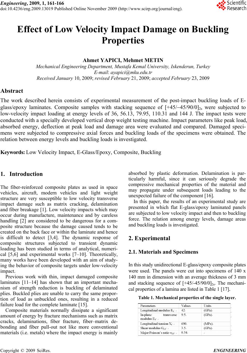 Engineering, 2009, 1, 161-166 doi:10.4236/eng.2009.13019 Published Online November 2009 (http://www.scirp.org/journal/eng). Copyright © 2009 SciRes. ENGINEERING Effect of Low Velocity Impact Damage on Buckling Properties Ahmet YAPICI, Mehmet METIN Mechanical Engineering Department, Mustafa Kemal University, Iskenderun, Turkey E-mail: ayapici@mku.edu.tr Received January 10, 2009; revised February 21, 2009; accepted February 23, 2009 Abstract The work described herein consists of experimental measurement of the post-impact buckling loads of E- glass/epoxy laminates. Composite samples with stacking sequence of [+45/45/90/0]2s were subjected to low-velocity impact loading at energy levels of 36, 56.13, 79.95, 110.31 and 144 J. The impact tests were conducted with a specially developed vertical drop weight testing machine. Impact parameters like peak load, absorbed energy, deflection at peak load and damage area were evaluated and compared. Damaged speci- mens were subjected to compressive axial forces and buckling loads of the specimens were obtained. The relation between energy levels and buckling loads is investigated. Keywords: Low Velocity Impact, E-Glass/Epoxy, Composite, Buckling 1. Introduction The fiber-reinforced composite plates as used in space vehicles, aircraft, modern vehicles and light weight structure are very susceptible to low velocity transverse impact damage such as matrix cracking, delamination and fiber breakage [1]. Low velocity impacts which may occur during manufacture, maintenance and by careless handling [2] are considered to be dangerous for a com- posite structure because the damage caused tends to be created on the back face or within the laminate and hence is difficult to detect [3,4]. The dynamic response of composite structures subjected to transient dynamic loading has been studied in terms of analytical, numeri- cal [5,6] and experimental works [7–10]. Theoretically, many works have been developed with an aim of study- ing the behavior of composite targets under low-velocity impact. Previous work with thin, impact damaged composite laminates [11–14] has shown that an important mecha- nism of strength reduction is buckling of delaminated plies. Buckled plies are unable to carry the same propor- tion of load as unbuckled ones, resulting in a reduced failure load for the complete laminate [15]. Composite materials normally dissipate a significant amount of energy by fracture mechanisms such as matrix cracks, delaminations, fiber fracture, fiber–matrix de- bonding and fiber pull-out not like more conventional materials (i.e. metals) where the impact energy is mainly absorbed by plastic deformation. Delamination is par- ticularly harmful, since it can seriously degrade the compressive mechanical properties of the material and may propagate under subsequent loads leading to the unexpected failure of the component [16]. In this paper, the results of an experimental study are presented in which flat E-glass/epoxy laminated panels are subjected to low velocity impact and then to buckling force. The relation among energy levels, damage areas and buckling loads is investigated. 2. Experimental 2.1. Materials and Specimens In this study unidirectional E-glass/epoxy composite plates were used. The panels were cut into specimens of 140 x 140 mm in dimension with an average thickness of 3 mm and stacking sequence of [+45/-45/90/0]2s. The mechani- cal properties of a lamina are listed in Table 1 [17]. Table 1. Mechanical properties of the single layer. 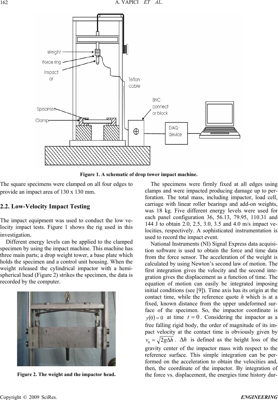 A. YAPICI ET AL. 162 Figure 1. A schematic of drop tower impact machine. The square specimens were clamped on all four edges to provide an impact area of 130 x 130 mm. 2.2. Low-Velocity Impact Testing The impact equipment was used to conduct the low ve- locity impact tests. Figure 1 shows the rig used in this investigation. Different energy levels can be applied to the clamped specimen by using the impact machine. This machine has three main parts; a drop weight tower, a base plate which holds the specimen and a control unit housing. When the weight released the cylindrical impactor with a hemi- spherical head (Figure 2) strikes the specimen, the data is recorded by the computer. Figure 2. The weight and the impactor head. The specimens were firmly fixed at all edges using clamps and were impacted producing damage up to per- foration. The total mass, including impactor, load cell, carriage with linear roller bearings and add-on weights, was 18 kg. Five different energy levels were used for each panel configuration 36, 56.13, 79.95, 110.31 and 144 J to obtain 2.0, 2.5, 3.0, 3.5 and 4.0 m/s impact ve- locities, respectively. A sophisticated instrumentation is used to record the impact event. National Instruments (NI) Signal Express data acquisi- tion software is used to obtain the force and time data from the force sensor. The acceleration of the weight is calculated by using Newton’s second law of motion. The first integration gives the velocity and the second inte- gration gives the displacement as a function of time. The equation of motion can easily be integrated imposing initial conditions (see [9]). Time axis has its origin at the contact time, while the reference quote h which is at a fixed, known distance from the upper undeformed sur- face of the specimen. So, the impactor coordinate is 00 y at time 0 t. Considering the impactor as a free falling rigid body, the order of magnitude of its im- pact velocity at the contact time is obviously given by hgv 2 0. h is defined as the height loss of the gravity center of the impactor mass with respect to the reference surface. This simple integration can be per- formed on the acceleration to obtain the velocities and, then, the coordinate of the impactor. By integration of the force vs. displacement, the energies time history dur- C opyright © 2009 SciRes. ENGINEERING 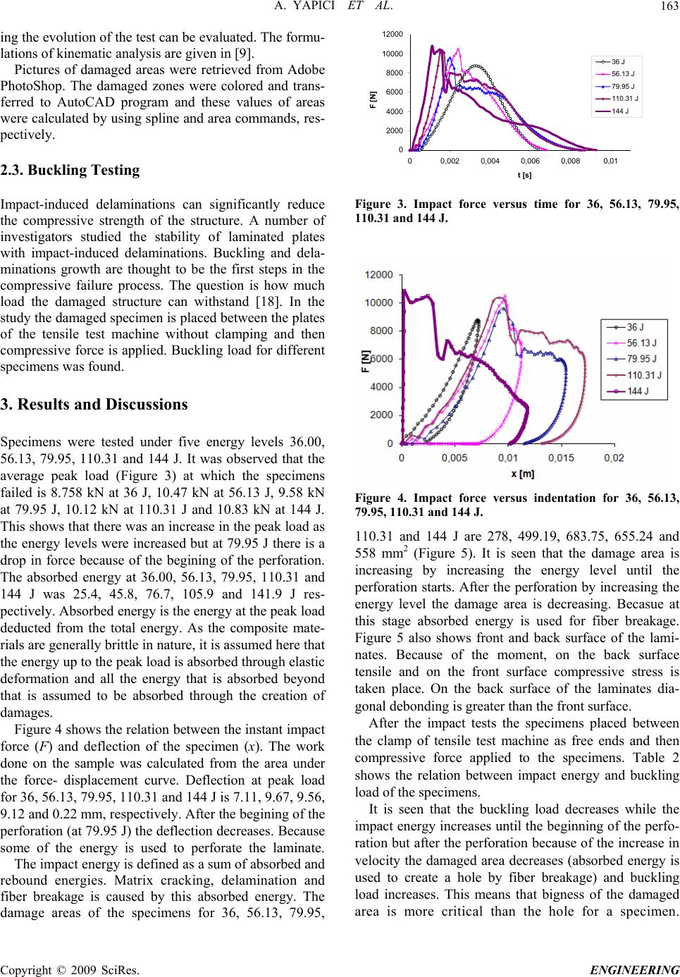 A. YAPICI ET AL.163 ing the evolution of the test can be evaluated. The formu- lations of kinematic analysis are given in [9]. Pictures of damaged areas were retrieved from Adobe PhotoShop. The damaged zones were colored and trans- ferred to AutoCAD program and these values of areas were calculated by using spline and area commands, res- pectively. 2.3. Buckling Testing Impact-induced delaminations can significantly reduce the compressive strength of the structure. A number of investigators studied the stability of laminated plates with impact-induced delaminations. Buckling and dela- minations growth are thought to be the first steps in the compressive failure process. The question is how much load the damaged structure can withstand [18]. In the study the damaged specimen is placed between the plates of the tensile test machine without clamping and then compressive force is applied. Buckling load for different specimens was found. 3. Results and Discussions Specimens were tested under five energy levels 36.00, 56.13, 79.95, 110.31 and 144 J. It was observed that the average peak load (Figure 3) at which the specimens failed is 8.758 kN at 36 J, 10.47 kN at 56.13 J, 9.58 kN at 79.95 J, 10.12 kN at 110.31 J and 10.83 kN at 144 J. This shows that there was an increase in the peak load as the energy levels were increased but at 79.95 J there is a drop in force because of the begining of the perforation. The absorbed energy at 36.00, 56.13, 79.95, 110.31 and 144 J was 25.4, 45.8, 76.7, 105.9 and 141.9 J res- pectively. Absorbed energy is the energy at the peak load deducted from the total energy. As the composite mate- rials are generally brittle in nature, it is assumed here that the energy up to the peak load is absorbed through elastic deformation and all the energy that is absorbed beyond that is assumed to be absorbed through the creation of damages. Figure 4 shows the relation between the instant impact force (F) and deflection of the specimen (x). The work done on the sample was calculated from the area under the force- displacement curve. Deflection at peak load for 36, 56.13, 79.95, 110.31 and 144 J is 7.11, 9.67, 9.56, 9.12 and 0.22 mm, respectively. After the begining of the perforation (at 79.95 J) the deflection decreases. Because some of the energy is used to perforate the laminate. The impact energy is defined as a sum of absorbed and rebound energies. Matrix cracking, delamination and fiber breakage is caused by this absorbed energy. The damage areas of the specimens for 36, 56.13, 79.95, 0 2000 4000 6000 8000 10000 12000 00,002 0,004 0,006 0,0080,01 F [N] t [s] 36 J 56.13 J 79.95 J 110.31 J 144 J Figure 3. Impact force versus time for 36, 56.13, 79.95, 110.31 and 144 J. Figure 4. Impact force versus indentation for 36, 56.13, 79.95, 110.31 and 144 J. 110.31 and 144 J are 278, 499.19, 683.75, 655.24 and 558 mm2 (Figure 5). It is seen that the damage area is increasing by increasing the energy level until the perforation starts. After the perforation by increasing the energy level the damage area is decreasing. Becasue at this stage absorbed energy is used for fiber breakage. Figure 5 also shows front and back surface of the lami- nates. Because of the moment, on the back surface tensile and on the front surface compressive stress is taken place. On the back surface of the laminates dia- gonal debonding is greater than the front surface. After the impact tests the specimens placed between the clamp of tensile test machine as free ends and then compressive force applied to the specimens. Table 2 shows the relation between impact energy and buckling load of the specimens. It is seen that the buckling load decreases while the impact energy increases until the beginning of the perfo- ration but after the perforation because of the increase in velocity the damaged area decreases (absorbed energy is used to create a hole by fiber breakage) and buckling load increases. This means that bigness of the damaged area is more critical than the hole for a specimen. Copyright © 2009 SciRes. ENGINEERING 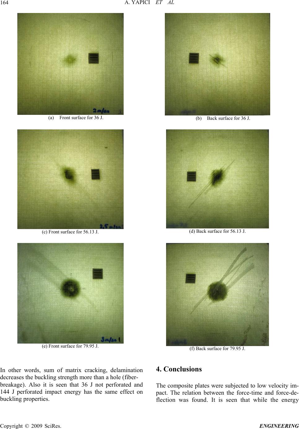 A. YAPICI ET AL 164 (a) Front surface for 36 J. (b) Back surface for 36 J. (c) Front surface for 56.13 J. (d) Back surface for 56.13 J. (e) Front surface for 79.95 J. (f) Back surface for 79.95 J. In other words, sum of matrix cracking, delamination decreases the buckling strength more than a hole (fiber- breakage). Also it is seen that 36 J not perforated and 144 J perforated impact energy has the same effect on buckling properties. 4. Conclusions The composite plates were subjected to low velocity im- pact. The relation between the force-time and force-de- flection was found. It is seen that while the energy C opyright © 2009 SciRes. ENGINEERING 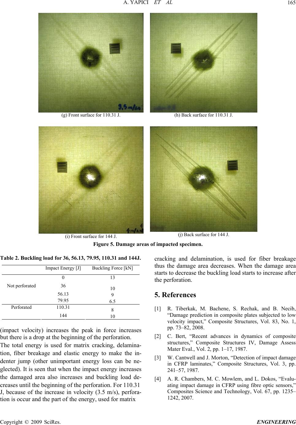 A. YAPICI ET AL 165 (g) Front surface for 110.31 J. (h) Back surface for 110.31 J. (i) Front surface for 144 J. (j) Back surface for 144 J. Figure 5. Damage areas of impacted specimen. Table 2. Buckling load for 36, 56.13, 79.95, 110.31 and 144J. Impact Energy [J] Buckling Force [kN] 0 13 36 10 56.13 9 Not perforated 79.95 6.5 110.31 8 Perforated 144 10 (impact velocity) increases the peak in force increases but there is a drop at the beginning of the perforation. The total energy is used for matrix cracking, delamina- tion, fiber breakage and elastic energy to make the in- denter jump (other unimportant energy loss can be ne- glected). It is seen that when the impact energy increases the damaged area also increases and buckling load de- creases until the beginning of the perforation. For 110.31 J, because of the increase in velocity (3.5 m/s), perfora- tion is occur and the part of the energy, used for matrix cracking and delamination, is used for fiber breakage thus the damage area decreases. When the damage area starts to decrease the buckling load starts to increase after the perforation. 5. References [1] R. Tiberkak, M. Bachene, S. Rechak, and B. Necib, “Damage prediction in composite plates subjected to low velocity impact,” Composite Structures, Vol. 83, No. 1, pp. 73–82, 2008. [2] C. Bert, “Recent advances in dynamics of composite structures,” Composite Structures IV, Damage Assess Mater Eval., Vol. 2, pp. 1–17, 1987. [3] W. Cantwell and J. Morton, “Detection of impact damage in CFRP laminates,” Composite Structures, Vol. 3, pp. 241–57, 1987. [4] A. R. Chambers, M. C. Mowlem, and L. Dokos, “Evalu- ating impact damage in CFRP using fibre optic sensors,” Composites Science and Technology, Vol. 67, pp. 1235– 1242, 2007. C opyright © 2009 SciRes. ENGINEERING  A. YAPICI ET AL. Copyright © 2009 SciRes. ENGINEERING 166 [5] C. F. Li, N. Hu, Y. J. Yin, H. Sekine, and H. Fukunaga, “Low-velocity impact damage of continuous fiber rein- forced composite laminates,” Part I, An FEM Numerical Model, Composites: Part A, Vol. 33, pp. 1055–62, 2002. [6] C. F. Li, N. Hu, Y. G. Cheng, H. Fukunaga, and H. Se- kine, “Low-velocity impact-induced damage of continu- ous fiber-reinforced composite laminates,” Part II Verifi- cation and Numerical Investigation, Composites: Part A, 33, pp. 1063–72, 2002. [7] Z. Aslan, R. Karakuzu, and B. Okutan, “The response of laminated composite plates under low-velocity impact loading,” Composite Structures, Vol. 59, pp. 119–27, 2003. [8] F. Mili and B. Necib, “Impact behavior of cross-ply laminated composite plates under low velocities,” Com- posite Structures, Vol. 51, pp. 237–44, 2001. [9] M. Uyaner and M. Kara, “Dynamic Response of Lami- nated Composites Subjected to Low-velocity Impact,” Journal of Composite Materials, Vol. 41, No. 24, pp. 2877–2896, 2007. [10] B. Whittingham, I. H. Marshall, T. Mitrevski, and R. Jones, “The response of composite structures with pre-stress subject to low velocity impact damage,” Com- posite Structures, Vol. 66, pp. 685–698, 2004. [11] G. Clark, “Modelling of impact damage in composite laminates,” Composites, Vol. 20, pp. 209–14, 1989. [12] Y. Xiong, C. Poon, P. V. Straznicky, and H. Vietinghoff, “A prediction method for the compressive strength of impact damaged composite laminates,” Composite Structures, Vol. 30, pp. 357–67, 1995. [13] M. J. Pavier and M. P. Clarke, “Finite element prediction of post impact compressive strength in carbon fibre com- posites,” Composite Structures, Vol. 36, pp. 141–53, 1996. [14] M. de Freitas and L. Reis, “Failure mechanisms of com- posite specimens subjected to compression after impact,” Composite Structures, Vol. 42, pp. 365–73, 1998. [15] G. J. Short, F. J. Guild, and M. J. Pavier, “Post-impact compressive strength of curved GFRP laminates,” Com- posites: Part. A, Vol. 33, pp. 1487–1495, 2002. [16] F. Aymerich, C. Pani, and P. Priolo, “Effect of stitching on the low-velocity impact response of [03/903]s graph- ite/epoxy laminates,” Composites: Part. A, Vol. 38, pp. 1174–1182, 2007. [17] M. Metin, “The effect of low-velocity impact damage on buckling behavior of E-glass/epoxy laminated compos- ites,” M. S. Thesis in Mechanical Engineering, Selcuk University Konya, Turkey, 2008. [18] S. Abrate, “Impact on composite structure,” Cambridge University Press, NY, USA, 1998. |