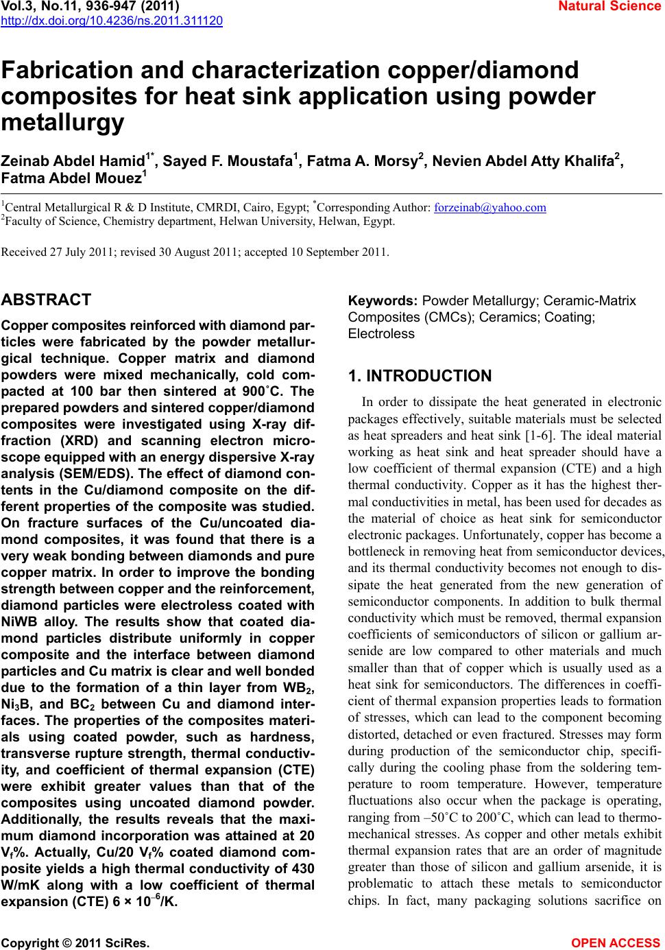
 Vol.3, No.11, 936-947 (2011) Natural Science http://dx.doi.org/10.4236/ns.2011.311120 Copyright © 2011 SciRes. OPEN ACCESS Fabrication and characterization copper/diamond composites for heat sink application using powder metallurgy Zeinab Abdel Hamid1*, Sayed F. Moustafa1, Fatma A. Morsy2, Nevien Abdel Atty Khalifa2, Fatma Abdel Mouez1 1Central Metallurgical R & D Institute, CMRDI, Cairo, Egypt; *Corresponding Author: forzeinab@yahoo.com 2Faculty of Science, Chemistry department, Helwan University, Helwan, Egypt. Received 27 July 2011; revised 30 August 2011; accepted 10 September 2011. ABSTRACT Copper composites reinforced with diamond par- ticles were fabricated by the powder metallur- gical technique. Copper matrix and diamond powders were mixed mechanically, cold com- pacted at 100 bar then sintered at 900˚C. The prepared powders and sintered copper/diamond composites were investigated using X-ray dif- fraction (XRD) and scanning electron micro- scope equipped with an energy dispersive X-ray analysis (SEM/EDS). The effect of diamond con- tents in the Cu/diamond composite on the dif- ferent properties of the composite was studied. On fracture surfaces of the Cu/uncoated dia- mond composites, it was found that there is a very weak bonding between diamonds and pure copper matrix. In order to improve the bonding strength between copper and the reinforcement, diamond particles were electroless coated with NiWB alloy. The results show that coated dia- mond particles distribute uniformly in copper composite and the interface between diamond particles and Cu matrix is clear and well bonded due to the formation of a thin layer from WB2, Ni3B, and BC2 between Cu and diamond inter- faces. The properties of the composites materi- als using coated powder, such as hardness, transverse rupture strength, thermal conductiv- ity, and coefficient of thermal expansion (CTE) were exhibit greater values than that of the composites using uncoated diamond powder. Additionally, the results reveals that the maxi- mum diamond incorporation was attained at 20 Vf%. Actually, Cu/20 Vf% coated diamond com- posite yields a high thermal conductivity of 430 W/mK along with a low coefficient of thermal expansion (CTE) 6 × 10⁻⁶/K. Keywords: Powder Metallurgy; Ceramic-Matrix Composites (CMCs); Ceramics; Coating; Electroless 1. INTRODUCTION In order to dissipate the heat generated in electronic packages effectively, suitable materials must be selected as heat spreaders and heat sink [1-6]. The ideal material working as heat sink and heat spreader should have a low coefficient of thermal expansion (CTE) and a high thermal conductivity. Copper as it has the highest ther- mal conductivities in metal, has been used for decades as the material of choice as heat sink for semiconductor electronic packages. Unfortunately, copper has become a bottleneck in removing heat from semiconductor devices, and its thermal conductivity becomes not enough to dis- sipate the heat generated from the new generation of semiconductor components. In addition to bulk thermal conductivity which must be removed, thermal expansion coefficients of semiconductors of silicon or gallium ar- senide are low compared to other materials and much smaller than that of copper which is usually used as a heat sink for semiconductors. The differences in coeffi- cient of thermal expansion properties leads to formation of stresses, which can lead to the component becoming distorted, detached or even fractured. Stresses may form during production of the semiconductor chip, specifi- cally during the cooling phase from the soldering tem- perature to room temperature. However, temperature fluctuations also occur when the package is operating, ranging from –50˚C to 200˚C, which can lead to thermo- mechanical stresses. As copper and other metals exhibit thermal expansion rates that are an order of magnitude greater than those of silicon and gallium arsenide, it is problematic to attach these metals to semiconductor chips. In fact, many packaging solutions sacrifice on  Z. A. Hamid et al. / Natural Science 3 (2011) 936-947 Copyright © 2011 SciRes. OPEN ACCESS 937937 thermal conductivity, choosing less efficient heat con- ductors such as ceramics in order to address this issue [6]. There is a great demand for a new material to be used as heat sink substrate. This new material should have high thermal conductivity greater than that of copper (i.e. as great as possible) in order to dissipate the high heat generated from the semiconductor component during operation, and in the same time its coefficient of thermal expansion must match as closely as possible to that of the semiconductor component. This new material could be developed by means of composite materials such as Cu/diamond composite. Since diamond is characterized by high thermal conductivity about 6 times that of cop- per but its disadvantage that its thermal expansion is smaller than that of semiconductors. So by adding cop- per to diamond we can have the required characteristics by controlling the percentages of copper to diamond [7-9]. The major problems encountered with “diamond on copper” synthesis are the low nucleation density, film cracking, and poor wetability. When diamond particles are embedded in a copper matrix, the interface plays a crucial role in determining the thermal conductivity, the CTE and also the mechanical properties of the composite. An ideal interface should provide good adhesion and minimum thermal boundary resistance. It is well known that alloying of copper with a strong carbide diamond forming element promotes wetting and bonding of diamond. Even in the case of solid phase bonding (e.g. hot pressing), high bonding strength was observed for copper alloys with minor additions of car- bides from (Ti, Cr, B or Zr) [10,11]. Chromium or tung- sten is believed to be a good promoter due to its abilities to inhibit bulk copper formation, to improve copper ther- mal stability and to increase copper dispersion. The main objective of this investigation is to synthesize and char- acterize Cu/diamond composite materials for electronic application obtained by powder metallurgy technique. Coating diamond particles using electroless technique added to the copper matrix to fabricate Cu/diamond composite has been investigated. Finally, the properties of Cu/coated diamond composites were compared with the same materials containing uncoated diamond. 2. EXPERIMENTAL PROCUDURES 2.1. General In the present work, the fabrication of Cu/diamond composites using powder metallurgy technique was in- vestigated in detail. The investigated diamond powders of micron grain sizes (20 - 40 µm) type RVD were sup- plied by Polaris Diamond Powder Co., Ltd. The dia- mond powder was electroless coated with NiWB. Cop- per powder using in this study has been fabricated using electroless technique. 2.2. Surface Treatment for Diamond and Electroless NiWB Plating As the diamond surface has higher interface energy, the adhesion of surface with the coating layer is bad, and it makes the diamond shatter easily. For solving this, the diamond surface must be treated and activated to im- prove the coating adhesion. The following steps were used for surface treatment. Washing by acetone (30 min.); etching by acidic solu- tion using 50% HNO3; sensitization using stannous chloride solution; activation using palladium chloride solution; then immersed in the plating solution [12]. The diamond after sensitization and activation were chemically coated with NiWB. The chemical composi- tion and the operating conditions of the plating solution were illustrated in Table 1. Additionally, the chemical composition and the operating conditions for producing the copper powder using electroless technique were il- lustrated in Table 2. Analytical reagents and distilled water were used to prepare the plating solutions. Table 1. Chemical composition and operating conditions of electroless NiWB plating solution. Composition Concentration, gl–1 NiWB Nickel sulphate 10 sodium citrate 20 Dimethyl amine borane (DMAB) 0.4 sodium Tungestate 20 Operating conditions Temperature, ˚C 85 pH 6.5 Time, hrs 2 Table 2. The chemical composition and the operating condi- tions of electroless copper solution. Composition Concentration gl–1 Copper sulphate 35 Sodium potassium tartrate 170 Sodium hydroxxide 50 Formaline 200 mlL–1 Operating conditions pH 11 - 13 Temperature, ˚C 25  Z. A. Hamid et al. / Natural Science 3 (2011) 936-947 Copyright © 2011 SciRes. OPEN ACCESS 938 2.3. Composites Production The amount of powder and coating thickness must be controlled during the production of composite. If a too large amount of diamond or a too thick coating for the functional layer is used the thermal conductivity of the copper matrix material will be reduced very severe. The copper powders were mixed with the diamond particles to prepare composites then milled for 20 min, compacted under the pressure 100 bar then sintered at 900˚C for 1 hr using hydrogen atmosphere. 2.4. Analysis and Characterizations Scanning electron microscope (SEM) with a link en- ergy dispersive X-ray spectroscopy (EDS) detector at- tachment, model JEOL, JSM-5410, were used to assess the surface morphology, particle size, particle shape, agglomeration of particles and the compositions of the various Cu/diamond composites. For SEM, the dry powder was dusted onto a carbon tape, which was stuck onto the copper holder disk of the microscope, gently blown with compressed air before introducing into the microscope chamber. The phase identification was determined using X-ray diffraction PANalytical X’pert PRO (45 kv/40 mA) ad- vanced with Cu target (λ = 1.54 A0). The boron content of the NiWB thin film deposited was determined by in- ductively coupled plasma-mass spectrometer (ICP-MS) after dissolving the deposited layer in nitric acid solu- tion. 2.5. The Densities Measurements The densities of the sintered powders were measured according to MPIF Standards 42, 1998, using Archimedes rule. The density (δ) of the samples was calculated ac- cording to the following formula [13,14]: aaw WWW gm/cm3 (1) where Wa and Ww are the weights in air and water re- spectively. 2.6. The Electrical Resistivity Measurements The electrical resistivity of the sintered materials was measured using the four-probe method by using Omega CL 8400 micrometer device. The rectangular sintered specimen was placed in a specially designed jig for mak- ing the electrical connection. Measurements were taken for the longitudinal and the transverse directions of the sample. The resistivity ( ) was calculated according to the following equation by using High Precision Micro- ohmmeter. RA L (2) where, R is the resistance in micro ohm, L is the meas- ured length in cm, A is the cross section area in cm2, and ρ is the resistivity in µ··cm. 2.7. The Macrohardness Measurements The macrohardness values of the investigated materi- als were measured as the average of 5 readings over the surface of the specimens using Vicker’s macrohardness Test type HPV 30 A and the using load was 5 kg for 15 s. 2.8. Transverse Rupture Strength (TRS) Measurements The rupture test was performed using compression testing machine and a test fixture, according to MPIF Standard 41. All the samples of the powders were com- pacted into rectangular compacts of dimension of (30 × 10 × 6) mm3. In the transverse rupture fixture, the test bar was placed centrally located and perpendicular to the supporting rods with the top up. The fixture with the test bar was placed between the plates of the compression testing machine and the load was applied at constant rate of 2.5 mm/min, until the test bar fractured. The trans- verse rupture strength for sintered samples was calcu- lated according to the following expression [13]: 2 3 2 PL TRS tW (3) where: TRS = Transverse rupture strength in N/mm2 P = Fracturing (rupture) load (N) L = the distance between the supporting rods (25.4 mm) t = the thickness of the sample in (mm) W = the width of the sample in (mm) 2.9. Coefficient of Thermal Expansion (CTE) CTE was measured with a Netzsch dilatometer model 402 C push rod. The samples were tested in open air between 25˚C and 160˚C at a heating rate of 3 K/min. Further on, the reproducibility was checked by measur- ing the same sample twice. The system was calibrated with a copper standard prior to the sample test run. Co- efficient of thermal expansion (CTE) value at a given temperature was calculated from the thermal expansion curves (change in length versus temperature) recorded during heating up the specimen from room temperature up to 160˚C, according to this relationship: L CTE TL (4) where L represents the original length of the specimen  Z. A. Hamid et al. / Natural Science 3 (2011) 936-947 Copyright © 2011 SciRes. OPEN ACCESS 939939 and L stands for the length change after a thermal cy- cling. 2.10. Thermal Conductivity The thermal conductivity was calculated from electri- cal resistivity measurement using Wiedemann and Franz equation which derived a relation equation between the thermal and electrical conductivities [15]. The Wiede- mann-Franz equation is as follows: 22 82 2 π2.443 10JΩKs 3 B kL Te (5) where, is thermal conductivity (W/mK), is electrical conductivity μ·Ω·cm–1, T is absolute temperature in de- gree Kelvin, KB is Boltzmann constant, and L is Lorentz number. 3. RESULTS AND DISCUSSION 3.1. Surface Treatment of Diamond Powders Surface Cleaning and Etching The coating process of diamond powders is highly dependent on the pre-treatment of the powders them- selves. The first pretreatment step is to remove any for- eign matter may be existed from the reinforcement powders. Acetone was used to remove any organic mat- ter, such as grease or oil, and finally used 50% HNO3 for further cleaning the powder surfaces and also to etch their surfaces. This pretreatment increases the ability of diamond surface to be coated, increases the homogeneity of the coating film and improves the adhesion of coating layer. Although the coating bath is the most visible and complex, any process problem is almost not due to the chemistry of the bath itself, but is more likely due to the pre-treatment of the surface of the substrate. Activation (Metallization) of Diamond Surfaces The main purpose of the metallization process for diamond powders is to etch and provide active sites that can react with the activators as well as to convert the hydrophobic to hydrophilic surface. Adding sensitized powders to the activation bath, the tin ions that are ad- sorbed on the diamond surfaces, reduce the palladium ions in the activation step according to the following equation: Sn+2 + Pd+2 Sn+4 + Pd0 (1) This step results in imparting a uniform surface film to the diamond powders, which ensures uniform adsorp- tion of subsequent coating and therefore promotes better coating [16]. 3.2. NiWB Electroless Plating The coatings are deposited on the surface of diamond found in the solution once its pH value becomes 6.5 and its temperature 85˚C. NiWB coating process used in this investigation is a chemical reduction process by di- methyl amine borane (DMAB) which served as a reduc- ing agent to supply electrons for the reduction process. The diamond powders coated with NiWB are investi- gated by scanning electron microscope and the X-ray diffraction. The scanning electron micrograph of the diamond coated is shown in Figure 1. Continuous coat- ing is seen on the surfaces of diamond. Figure 2 illus- trated the chemical composition and the obtained aver- age data of the coated layer using EDS. It was interest- ing to note that the nickel content of the deposit is higher than the tungsten content, suggesting an anomalous be- havior that involves a preferential deposition of electro- chemically less noble in the deposit. Saito et al. [17] have also observed this anomaly and suggested that the low overvoltage for nickel deposition is the reason for its 90 μm40 μm × 750 × 1500 Figure 1. SEM image for the diamond coated with NiWB film. 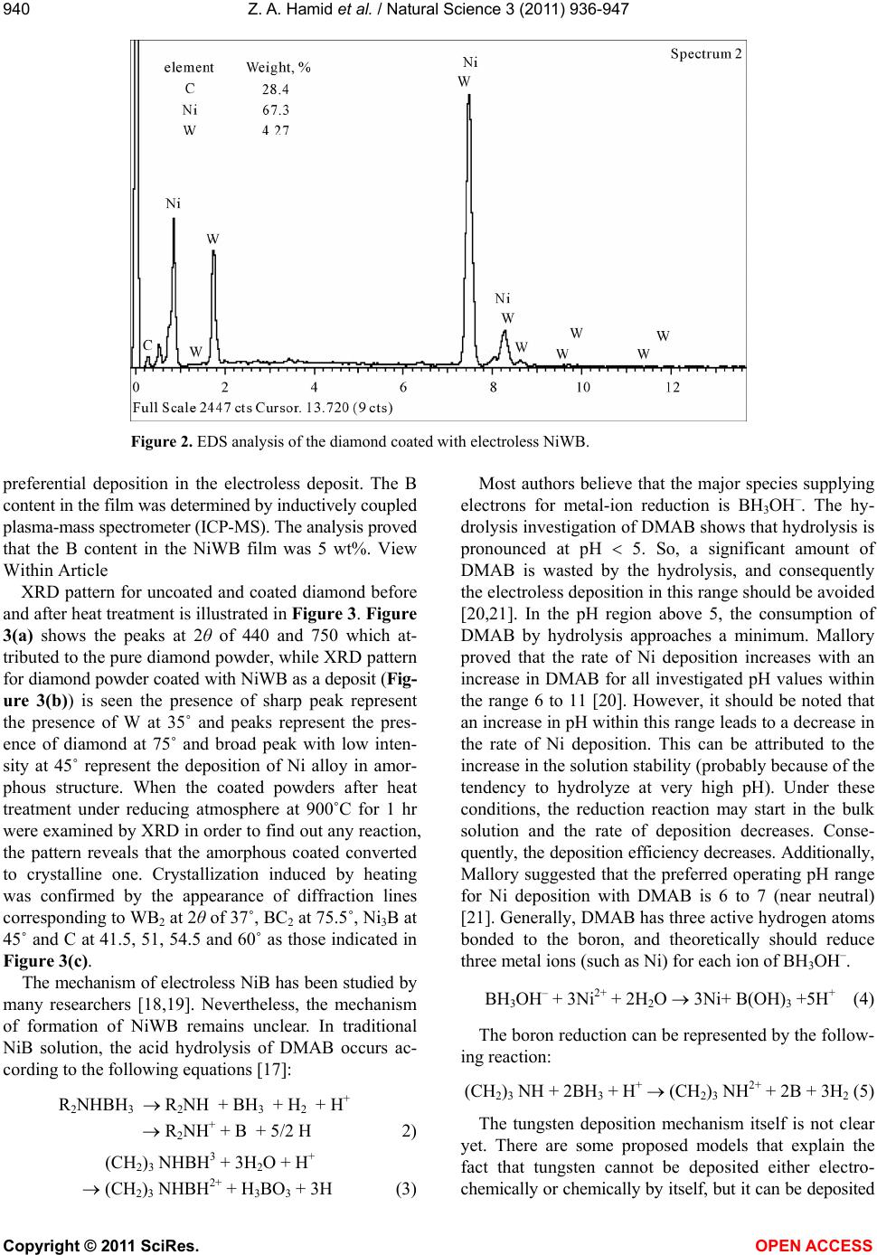 Z. A. Hamid et al. / Natural Science 3 (2011) 936-947 Copyright © 2011 SciRes. OPEN ACCESS 940 Figure 2. EDS analysis of the diamond coated with electroless NiWB. preferential deposition in the electroless deposit. The B content in the film was determined by inductively coupled plasma-mass spectrometer (ICP-MS). The analysis proved that the B content in the NiWB film was 5 wt%. View Within Article XRD pattern for uncoated and coated diamond before and after heat treatment is illustrated in Figure 3. Figure 3(a) shows the peaks at 2θ of 440 and 750 which at- tributed to the pure diamond powder, while XRD pattern for diamond powder coated with NiWB as a deposit (Fig- ure 3(b)) is seen the presence of sharp peak represent the presence of W at 35˚ and peaks represent the pres- ence of diamond at 75˚ and broad peak with low inten- sity at 45˚ represent the deposition of Ni alloy in amor- phous structure. When the coated powders after heat treatment under reducing atmosphere at 900˚C for 1 hr were examined by XRD in order to find out any reaction, the pattern reveals that the amorphous coated converted to crystalline one. Crystallization induced by heating was confirmed by the appearance of diffraction lines corresponding to WB2 at 2θ of 37˚, BC2 at 75.5˚, Ni3B at 45˚ and C at 41.5, 51, 54.5 and 60˚ as those indicated in Figure 3(c). The mechanism of electroless NiB has been studied by many researchers [18,19]. Nevertheless, the mechanism of formation of NiWB remains unclear. In traditional NiB solution, the acid hydrolysis of DMAB occurs ac- cording to the following equations [17]: R2NHBH3 R2NH + BH3 + H2 + H + R2NH + + B + 5/2 H 2) (CH2)3 NHBH3 + 3H2O + H+ (CH2)3 NHBH2+ + H3BO3 + 3H (3) Most authors believe that the major species supplying electrons for metal-ion reduction is BH3OH–. The hy- drolysis investigation of DMAB shows that hydrolysis is pronounced at pH 5. So, a significant amount of DMAB is wasted by the hydrolysis, and consequently the electroless deposition in this range should be avoided [20,21]. In the pH region above 5, the consumption of DMAB by hydrolysis approaches a minimum. Mallory proved that the rate of Ni deposition increases with an increase in DMAB for all investigated pH values within the range 6 to 11 [20]. However, it should be noted that an increase in pH within this range leads to a decrease in the rate of Ni deposition. This can be attributed to the increase in the solution stability (probably because of the tendency to hydrolyze at very high pH). Under these conditions, the reduction reaction may start in the bulk solution and the rate of deposition decreases. Conse- quently, the deposition efficiency decreases. Additionally, Mallory suggested that the preferred operating pH range for Ni deposition with DMAB is 6 to 7 (near neutral) [21]. Generally, DMAB has three active hydrogen atoms bonded to the boron, and theoretically should reduce three metal ions (such as Ni) for each ion of BH3OH–. BH3OH– + 3Ni2+ + 2H2O 3Ni+ B(OH)3 +5H+ (4) The boron reduction can be represented by the follow- ing reaction: (CH2)3 NH + 2BH3 + H+ (CH2)3 NH2+ + 2B + 3H2 (5) The tungsten deposition mechanism itself is not clear yet. There are some proposed models that explain the fact that tungsten cannot be deposited either electro- chemically or chemically by itself, but it can be deposited 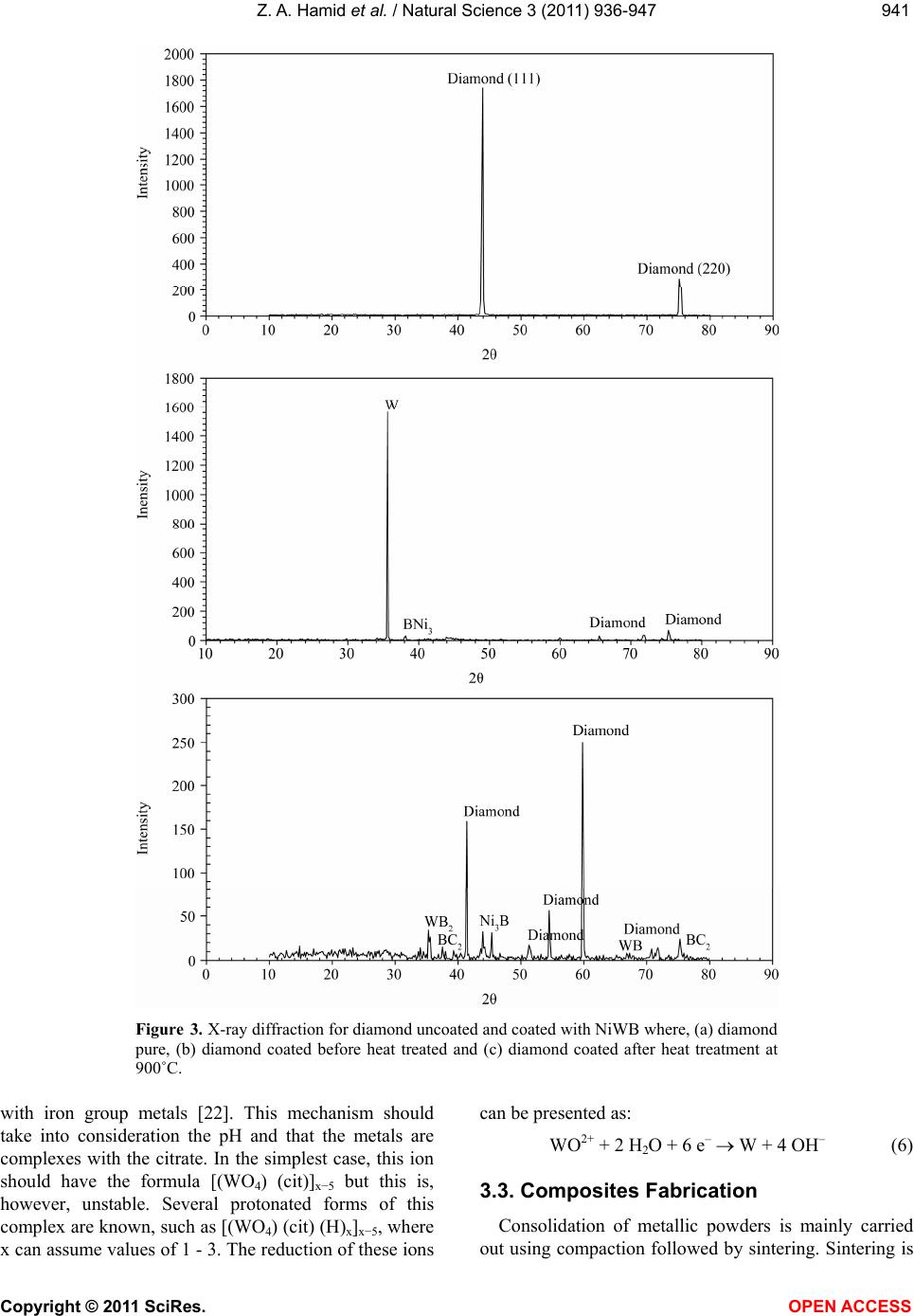 Z. A. Hamid et al. / Natural Science 3 (2011) 936-947 Copyright © 2011 SciRes. OPEN ACCESS 941941 Figure 3. X-ray diffraction for diamond uncoated and coated with NiWB where, (a) diamond pure, (b) diamond coated before heat treated and (c) diamond coated after heat treatment at 900˚C. with iron group metals [22]. This mechanism should take into consideration the pH and that the metals are complexes with the citrate. In the simplest case, this ion should have the formula [(WO4) (cit)]x−5 but this is, however, unstable. Several protonated forms of this complex are known, such as [(WO4) (cit) (H)x]x−5, where x can assume values of 1 - 3. The reduction of these ions can be presented as: WO2+ + 2 H2O + 6 e– W + 4 OH– (6) 3.3. Composites Fabrication Consolidation of metallic powders is mainly carried out using compaction followed by sintering. Sintering is 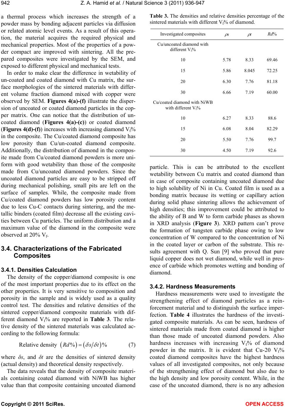 Z. A. Hamid et al. / Natural Science 3 (2011) 936-947 Copyright © 2011 SciRes. OPEN ACCESS 942 a thermal process which increases the strength of a powder mass by bonding adjacent particles via diffusion or related atomic level events. As a result of this opera- tion, the material acquires the required physical and mechanical properties. Most of the properties of a pow- der compact are improved with sintering. All the pre- pared composites were investigated by the SEM, and exposed to different physical and mechanical tests. In order to make clear the difference in wetability of un-coated and coated diamond with Cu matrix, the sur- face morphologies of the sintered materials with differ- ent volume fraction diamond mixed with copper were observed by SEM. Figures 4(a)-(f) illustrate the disper- sion of uncoated or coated diamond particles in the cop- per matrix. One can notice that the distribution of un- coated diamond (Figures 4(a)-(c)) or coated diamond (Figures 4(d)-(f)) increases with increasing diamond Vf% in the composite. The Cu/coated diamond composite has low porosity than Cu/un-coated diamond composite. Additionally, the distribution of diamond in the compos- ite made from Cu/coated diamond powders is more uni- form with good wetability than those of the composite made from Cu/uncoated diamond powders. Since the uncoated diamond particles are easy to be stripped off during mechanical polishing, small pits are left on the surface of samples. While, the composite made from Cu/coated diamond powders has low porosity content due to less Cu-C contacts during sintering, and the me- tallic binders (coated film) decrease all the existing cavi- ties between Cu particles. The uniform distribution and a maximum value of the diamond in the composite were observed at 20% Vf. 3.4. Characterizations of the Fabricated Composites 3.4.1. Densities Calculation The density of the copper/diamond composite is one of the most important properties due to its effect on the other properties. It is very sensitive to composition and porosity in the sample and is widely used as a quality control test. The densities and relative densities of the sintered copper/diamond composite materials with dif- ferent diamond Vf% are reported in Table 3. The rela- tive density of the sintered materials was calculated ac- cording to the following formula: Relative density %%Rds t (7) where δs, and δt are the densities of sintered density (actual density) and theoretical density respectively. The data reveals that the density of composite materi- als containing coated diamond with NiWB has higher value than that composite containing uncoated diamond Table 3. The densities and relative densities percentage of the sintered materials with different Vf% of diamond. Investigated composites s t Rd% Cu/uncoated diamond with different Vf% 10 5.78 8.33 69.46 15 5.86 8.045 72.25 20 6.30 7.76 81.18 30 6.66 7.19 60.00 Cu/coated diamond with NiWB with different Vf% 10 6.27 8.33 88.6 15 6.08 8.04 82.29 20 5.50 7.76 99.7 30 4.50 7.19 92.6 particle. This is can be attributed to the excellent wetability between Cu matrix and coated diamond than in case of composite containing uncoated diamond due to high solubility of Ni in Cu. Coated film is used as a bonding matrix because its wetting or capillary action during solid phase sintering allows the achievement of high densities; this improvement could be attributed to the ability of B and W to form carbide phases as shown in XRD analysis (Figure 3). XRD pattern can’t prove the formation of tungsten carbide phase owing to low concentration of W compared to the concentration of Ni in the coated layer or carbon of the substrate. This re- sults agreement with Q. Sun [9] who proved that pure liquid copper does not wet diamond, while well in pres- ence of carbide which promotes wetting and bonding of diamond. 3.4.2. Hardness Measurements Hardness measurements were used to investigate the strengthening effect of diamond particles as a rein- forcement material and to distinguish the surface imper- fection. Table 4 illustrates the hardness of the investi- gated composite materials. As can be seen, hardness of sintered materials made from coated diamond is higher than those made of uncoated diamond powders. Also hardness increases with increasing Vf% of diamond powder in the matrix. It is evident that Cu-20 Vf% coated diamond composites have the highest hardness values of all investigated composites, not only because of the strengthening effect of diamond but also due to the high density and low porosity content. While, in the case of the uncoated diamond, there is no any adhesion  Z. A. Hamid et al. / Natural Science 3 (2011) 936-947 Copyright © 2011 SciRes. OPEN ACCESS 943943 Figure 4. Surface morphologies of the as-polished Cu/uncoated diamond and Cu/NiWB coated diamond composites prepared by PM technique containing different Vf% diamond where: (a)-(c) Cu/10, 20, 30 Vf% uncoated diamond respectively and (d)-(f) Cu-10, 20, 30 Vf% NiWB coated diamond. or bond between the diamond and the copper matrix which causes the formation of pores in the final compos- ite and hence showed low hardness. 3.4.3. Electrical Conductivity Measurements The electro friction materials that exposed to high current densities or high voltages are produced from a composite material that having high electrical and ther- mal conductivities. Copper/diamond composite has a good sliding, antifriction properties, and high electrical and thermal conductivity [23]. The measured resistivity was converted to electrical conductivity IACS% (Inter- national Annealed Copper Standard) according to the ASTM standard B 193-72. The results of electrical resistivity measurements of the fabricated composites are shown in Table 5. It can be noticed that the electrical resistivity for all investi- gated Cu/diamond composites decreases with increasing Vf% of diamond up to 20 V% and then slightly increase. At the same time, the electrical resistivity for the com- posite fabricated from coated diamond with NiWB is lower than that of composite fabricated from uncoated diamond. This can be rationalized by the high porosity of the Cu/uncoated diamond composite. This porosity was resulted from the weak bond between diamond and the Cu matrix as shown in Figure 4. This in turn, creates voids, which decreases the mobility of the free electron causing high resistivity [24,25]. The electrical conductiv- ity is directly affected by porosity, the greater the void content the lower is the electrical conductivity. While, in 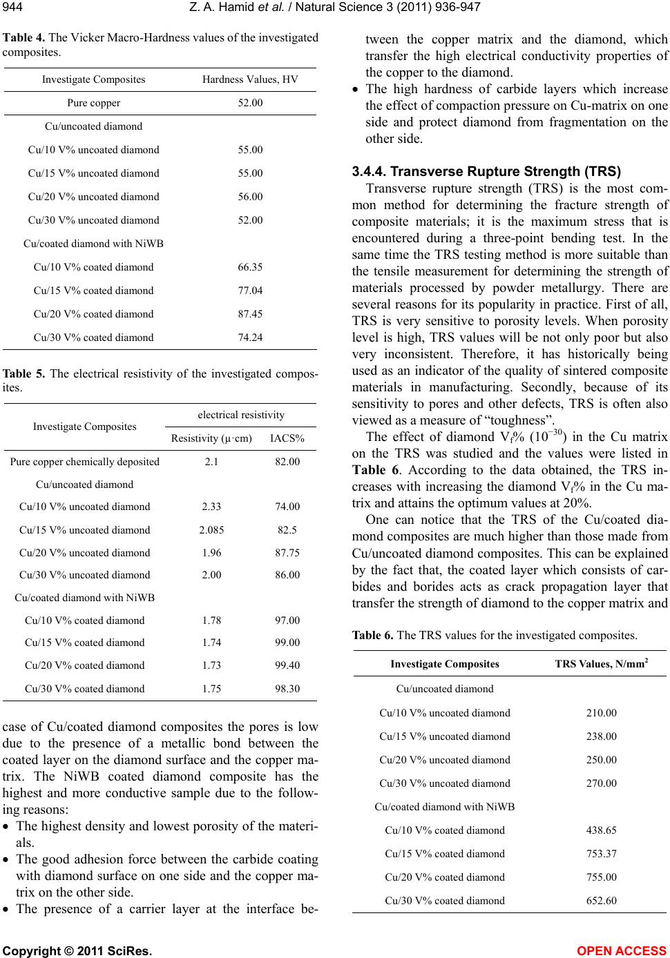 Z. A. Hamid et al. / Natural Science 3 (2011) 936-947 Copyright © 2011 SciRes. OPEN ACCESS 944 Table 4. The Vicker Macro-Hardness values of the investigated composites. Investigate Composites Hardness Values, HV Pure copper 52.00 Cu/uncoated diamond Cu/10 V% uncoated diamond 55.00 Cu/15 V% uncoated diamond 55.00 Cu/20 V% uncoated diamond 56.00 Cu/30 V% uncoated diamond 52.00 Cu/coated diamond with NiWB Cu/10 V% coated diamond 66.35 Cu/15 V% coated diamond 77.04 Cu/20 V% coated diamond 87.45 Cu/30 V% coated diamond 74.24 Table 5. The electrical resistivity of the investigated compos- ites. electrical resistivity Investigate Composites Resistivity (µ·cm) IACS% Pure copper chemically deposited 2.1 82.00 Cu/uncoated diamond Cu/10 V% uncoated diamond 2.33 74.00 Cu/15 V% uncoated diamond 2.085 82.5 Cu/20 V% uncoated diamond 1.96 87.75 Cu/30 V% uncoated diamond 2.00 86.00 Cu/coated diamond with NiWB Cu/10 V% coated diamond 1.78 97.00 Cu/15 V% coated diamond 1.74 99.00 Cu/20 V% coated diamond 1.73 99.40 Cu/30 V% coated diamond 1.75 98.30 case of Cu/coated diamond composites the pores is low due to the presence of a metallic bond between the coated layer on the diamond surface and the copper ma- trix. The NiWB coated diamond composite has the highest and more conductive sample due to the follow- ing reasons: The highest density and lowest porosity of the materi- als. The good adhesion force between the carbide coating with diamond surface on one side and the copper ma- trix on the other side. The presence of a carrier layer at the interface be- tween the copper matrix and the diamond, which transfer the high electrical conductivity properties of the copper to the diamond. The high hardness of carbide layers which increase the effect of compaction pressure on Cu-matrix on one side and protect diamond from fragmentation on the other side. 3.4.4. Transverse Rupture Strength (TRS) Transverse rupture strength (TRS) is the most com- mon method for determining the fracture strength of composite materials; it is the maximum stress that is encountered during a three-point bending test. In the same time the TRS testing method is more suitable than the tensile measurement for determining the strength of materials processed by powder metallurgy. There are several reasons for its popularity in practice. First of all, TRS is very sensitive to porosity levels. When porosity level is high, TRS values will be not only poor but also very inconsistent. Therefore, it has historically being used as an indicator of the quality of sintered composite materials in manufacturing. Secondly, because of its sensitivity to pores and other defects, TRS is often also viewed as a measure of “toughness”. The effect of diamond Vf% (10−30) in the Cu matrix on the TRS was studied and the values were listed in Table 6. According to the data obtained, the TRS in- creases with increasing the diamond Vf% in the Cu ma- trix and attains the optimum values at 20%. One can notice that the TRS of the Cu/coated dia- mond composites are much higher than those made from Cu/uncoated diamond composites. This can be explained by the fact that, the coated layer which consists of car- bides and borides acts as crack propagation layer that transfer the strength of diamond to the copper matrix and Table 6. The TRS values for the investigated composites. Investigate Composites TRS Values, N/mm2 Cu/uncoated diamond Cu/10 V% uncoated diamond 210.00 Cu/15 V% uncoated diamond 238.00 Cu/20 V% uncoated diamond 250.00 Cu/30 V% uncoated diamond 270.00 Cu/coated diamond with NiWB Cu/10 V% coated diamond 438.65 Cu/15 V% coated diamond 753.37 Cu/20 V% coated diamond 755.00 Cu/30 V% coated diamond 652.60 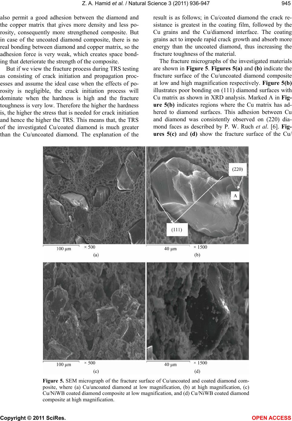 Z. A. Hamid et al. / Natural Science 3 (2011) 936-947 Copyright © 2011 SciRes. OPEN ACCESS 945945 also permit a good adhesion between the diamond and the copper matrix that gives more density and less po- rosity, consequently more strengthened composite. But in case of the uncoated diamond composite, there is no real bonding between diamond and copper matrix, so the adhesion force is very weak, which creates space bond- ing that deteriorate the strength of the composite. But if we view the fracture process during TRS testing as consisting of crack initiation and propagation proc- esses and assume the ideal case when the effects of po- rosity is negligible, the crack initiation process will dominate when the hardness is high and the fracture toughness is very low. Therefore the higher the hardness is, the higher the stress that is needed for crack initiation and hence the higher the TRS. This means that, the TRS of the investigated Cu/coated diamond is much greater than the Cu/uncoated diamond. The explanation of the result is as follows; in Cu/coated diamond the crack re- sistance is greatest in the coating film, followed by the Cu grains and the Cu/diamond interface. The coating grains act to impede rapid crack growth and absorb more energy than the uncoated diamond, thus increasing the fracture toughness of the material. The fracture micrographs of the investigated materials are shown in Figure 5. Figures 5(a) and (b) indicate the fracture surface of the Cu/uncoated diamond composite at low and high magnification respectively. Figure 5(b) illustrates poor bonding on (111) diamond surfaces with Cu matrix as shown in XRD analysis. Marked A in Fig- ure 5(b) indicates regions where the Cu matrix has ad- hered to diamond surfaces. This adhesion between Cu and diamond was consistently observed on (220) dia- mond faces as described by P. W. Ruch et al. [6]. Fig- ures 5(c) and (d) show the fracture surface of the Cu/ Figure 5. SEM micrograph of the fracture surface of Cu/uncoated and coated diamond com- posite, where (a) Cu/uncoated diamond at low magnification, (b) at high magnification, (c) Cu/NiWB coated diamond composite at low magnification, and (d) Cu/NiWB coated diamond composite at high magnification. 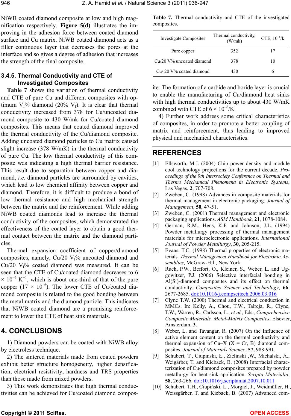 Z. A. Hamid et al. / Natural Science 3 (2011) 936-947 Copyright © 2011 SciRes. OPEN ACCESS 946 NiWB coated diamond composite at low and high mag- nification respectively. Figure 5(d) illustrates the im- proving in the adhesion force between coated diamond surface and Cu matrix. NiWB coated diamond acts as a filler continuous layer that decreases the pores at the interface and so gives a degree of adhesion that increases the strength of the final composite. 3.4.5. Thermal Conductivity and CTE of Investigated Composites Table 7 shows the variation of thermal conductivity and CTE of pure Cu and different composites with op- timum Vf% diamond (20% Vf). It is clear that thermal conductivity increased from 378 for Cu/uncoated dia- mond composite to 430 W/mk for Cu/coated diamond composites. This means that coated diamond improved the thermal conductivity of the Cu/diamond composite. Adding uncoated diamond particles to Cu matrix caused slight increase (378 W/mK) in the thermal conductivity of pure Cu. The low thermal conductivity of this com- posite was indicating a high thermal barrier resistance. This result due to separation between copper and dia- mond, i.e. diamond particles are surrounded by cavities, which lead to low chemical affinity between copper and diamond. Therefore, it is difficult to produce a bond of low thermal resistance and high mechanical strength between the matrix and the reinforcement. While adding NiWB coated diamonds lead to increase the thermal conductivity of the composites, which demonstrated the effectiveness of the coated layer to obtain a good ther- mal contact between the matrix and the diamond parti- cles. Thermal expansion coefficient of copper/diamond composites, namely, Cu/20 Vf% uncoated diamond and Cu/20 Vf% coated diamond was measured. It can be seen that the CTE of Cu/coated diamond decreases to 6 × 10⁻⁶ K−1, which is about one-third of that of the pure copper (17 × 10–6). The lower CTE of Cu/coated dia- mond composite is related to the good bonding between the metal matrix and the diamond particle. This indicates that NiWB coated diamond are a promising reinforce- ment to lower the CTE of heat sink materials. 4. CONCLUSIONS 1) Diamond powders can be coated with NiWB alloy by electroless technique. 2) The sintered materials made from coated powders exhibit better structure homogeneity, higher densifica- tion, electrical resistivity, hardness and TRS properties than those made from mixed powders. 3) This work demonstrates that high thermal conduc- tivities can be achieved for Cu/coated diamond compos- Table 7. Thermal conductivity and CTE of the investigated composites. Investigate Composites Thermal conductivity, (W/mk) CTE, 10–6/k Pure copper 352 17 Cu/20 V% uncoated diamond378 10 Cu/ 20 V% coated diamond430 6 ite. The formation of a carbide and boride layer is crucial to enable the manufacturing of Cu/diamond heat sinks with high thermal conductivities up to about 430 W/mK combined with CTE of 6 × 10⁻⁶/K. 4) Further work address some critical characteristics of composites, in order to promote a better coupling of matrix and reinforcement, thus leading to improved physical and mechanical characteristics. REFERENCES [1] Ellsworth, M.J. (2004) Chip power density and module cool technology projections for the current decade. Pro- ceedings of the 9th Intersociety Conference on Thermal and Thermo Mechanical Phenomena in Electronic Systems, Las Vegas, 2, 707-708. [2] Zweben, C. (1998) Advances in composite materials for thermal management in electronic packaging. Journal of Management, 50, 47-51. [3] Zweben, C. (2001) Thermal management and electronic packaging applications. ASM Handbook, 21, 1078-1084. [4] German, R.M., Hens, K.F. and Johnson, J.L. (1994) Powder metallurgy processing of thermal management materials for microelectronic applications. International Journal of Powder Metallurgy, 30, 205-215. [5] Evans, T.C. (1998) Thermal properties of electronic ma- terials. Thermal Management Handbook for Electronic As- semblies, McGraw-Hill, New York. [6] Ruch, P.W., Beffort, O., Kleiner, S., Weber, L. and Ug- gowitzer, P.J. (2006) Selective interfacial bonding in Al(Si)-diamond composites and its effect on thermal conductivity. Composites Science and Technology, 66, 2677-2685. doi:10.1016/j.compscitech.2006.03.016 [7] Clyne T.W. (2000) Thermal and electrical conduction in MMCs. In: Kelly, A., Chou, T.W., Talreja, R., Clyne, T.W., Warren, R., Carlsson, L., et al., Eds., Comprehensive Composite Materials. Metal-Matrix Composites, Elsevier, Amsterdam, 3. [8] Weber, L. and Tavangar, R. (2007) On the Influence of active element content on the thermal conductivity and thermal expansion of Cu–X (X = Cr, B) diamond com- posites. Journal of Materials Science, 57, 988-991. [9] Schubert, T., Ciupinski, Ł., Zielinski ,W., Michalski, A., Weigärber, T. and Kieback, B. (2008) Interfacial charac- terization of Cu/diamond composites prepared by powder metallurgy for heat sink application. Scripta Materialia, 58, 263-266. doi:10.1016/j.scriptamat.2007.10.011 [10] Schubert, T.H., Ciupiński, Ł., Morgiel, J., Weidmüller, H., Weissgärber, T. and Kieback, B. (2007) Advanced com- 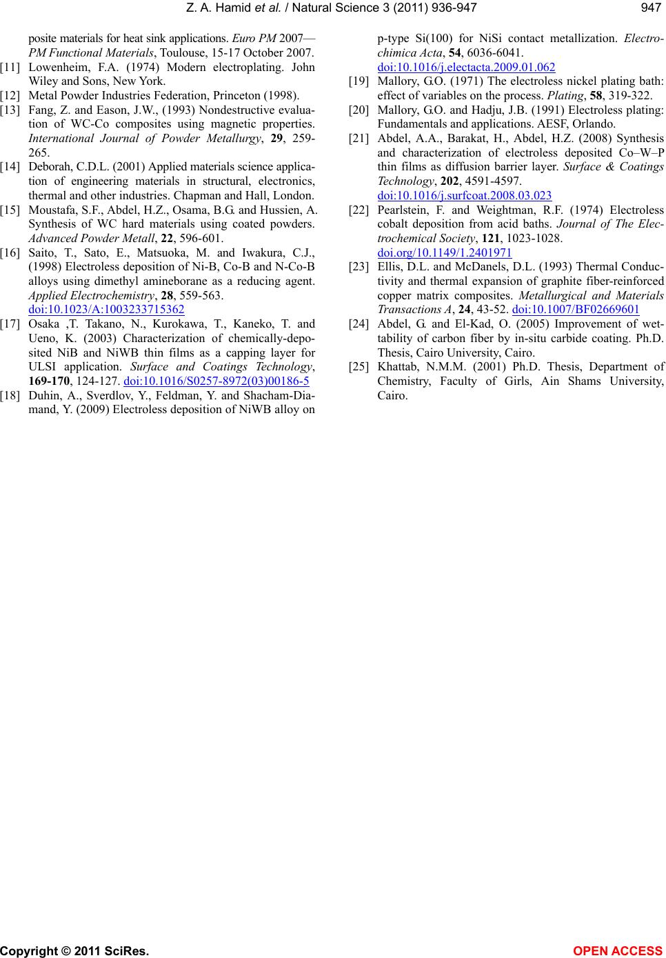 Z. A. Hamid et al. / Natural Science 3 (2011) 936-947 Copyright © 2011 SciRes. OPEN ACCESS 947947 posite materials for heat sink applications. Euro PM 2007— PM Functional Materials, Toulouse, 15-17 October 2007. [11] Lowenheim, F.A. (1974) Modern electroplating. John Wiley and Sons, New York. [12] Metal Powder Industries Federation, Princeton (1998). [13] Fang, Z. and Eason, J.W., (1993) Nondestructive evalua- tion of WC-Co composites using magnetic properties. International Journal of Powder Metallurgy, 29 , 259- 265. [14] Deborah, C.D.L. (2001) Applied materials science applica- tion of engineering materials in structural, electronics, thermal and other industries. Chapman and Hall, London. [15] Moustafa, S.F., Abdel, H.Z., Osama, B.G. and Hussien, A. Synthesis of WC hard materials using coated powders. Advanced Powder Metall, 22, 596-601. [16] Saito, T., Sato, E., Matsuoka, M. and Iwakura, C.J., (1998) Electroless deposition of Ni-B, Co-B and N-Co-B alloys using dimethyl amineborane as a reducing agent. Applied Electrochemistry, 28, 559-563. doi:10.1023/A:1003233715362 [17] Osaka ,T. Takano, N., Kurokawa, T., Kaneko, T. and Ueno, K. (2003) Characterization of chemically-depo- sited NiB and NiWB thin films as a capping layer for ULSI application. Surface and Coatings Technology, 169-170, 124-127. doi:10.1016/S0257-8972(03)00186-5 [18] Duhin, A., Sverdlov, Y., Feldman, Y. and Shacham-Dia- mand, Y. (2009) Electroless deposition of NiWB alloy on p-type Si(100) for NiSi contact metallization. Electro- chimica Acta, 54, 6036-6041. doi:10.1016/j.electacta.2009.01.062 [19] Mallory, G.O. (1971) The electroless nickel plating bath: effect of variables on the process. Plating, 58, 319-322. [20] Mallory, G.O. and Hadju, J.B. (1991) Electroless plating: Fundamentals and applications. AESF, Orlando. [21] Abdel, A.A., Barakat, H., Abdel, H.Z. (2008) Synthesis and characterization of electroless deposited Co–W–P thin films as diffusion barrier layer. Surface & Coatings Technology, 202, 4591-4597. doi:10.1016/j.surfcoat.2008.03.023 [22] Pearlstein, F. and Weightman, R.F. (1974) Electroless cobalt deposition from acid baths. Journal of The Elec- trochemical Society, 121, 1023-1028. doi.org/10.1149/1.2401971 [23] Ellis, D.L. and McDanels, D.L. (1993) Thermal Conduc- tivity and thermal expansion of graphite fiber-reinforced copper matrix composites. Metallurgical and Materials Transactions A, 24, 43-52. doi:10.1007/BF02669601 [24] Abdel, G. and El-Kad, O. (2005) Improvement of wet- tability of carbon fiber by in-situ carbide coating. Ph.D. Thesis, Cairo University, Cairo. [25] Khattab, N.M.M. (2001) Ph.D. Thesis, Department of Chemistry, Faculty of Girls, Ain Shams University, Cairo.
|