

Open Access Library Journal
Vol.05 No.07(2018), Article ID:85911,21 pages
10.4236/oalib.1104671
Numerical Modeled Static Stress-Deformed State of Parallel Pipes in the Deformable Environment
Ismail Ibrahimovich Safarov
Tashkent Institute of Chemistry and Technology, Tashkent, Republic of Uzbekistan

Copyright © 2018 by author and Open Access Library Inc.
This work is licensed under the Creative Commons Attribution International License (CC BY 4.0).
http://creativecommons.org/licenses/by/4.0/



Received: May 21, 2018; Accepted: July 8, 2018; Published: July 11, 2018
ABSTRACT
The paper considers the static pressure of the environment on the parallel pipe. The environment is elastic and homogeneous bodies. To determine the ambient pressure, the finite element method is used. An algorithm was developed and a computer program was compiled. Based on the compiled program, numerical results are obtained. The numerical results obtained for two to five parallel pipes are compared with known theoretical and experimental results.
Subject Areas:
Continuum Mechanics
Keywords:
Pipe, Finite Element Method, Static Pressure, Environment, Possible Displacements, Calculation Area

1. Introduction
At present, and in the coming decades, ensuring the operational reliability of the linear part of multi-thread underground pipelines is and will continue to be a complex scientific and engineering problem. In the modern design, various software packages of automated design are widely used, allowing to carry out the engineering analysis of computer models without resorting to real experiments. The most common and efficient calculation method is the finite element method (FEM). When determining the pressure of the soil on the pipes, it is necessary to take into account such factors as: the number of threads, the topography of the embankment, the conditions of supporting the pipes and other factors encountered in design practice. Accounting for other factors in analytical solutions is either extremely complex, or in general is impossible because of the difficulties that arise in this case of a mathematical nature. Various factors encountered in project practice can be accounted for using numerical methods. Recently, when solving various kinds of applied problems, the finite element method (FEM) is widely used. A number of works are known in which domestic [1] [2] [3] [4] and foreign authors [5] [6] successfully apply FEM to determine the soil pressure on a single laid extended pipe, under various conditions of its support, taking into account the heterogeneity of the soil composing the body mounds of constant height (flat deformation).
2. Statement of the Problem by the Finite Element Method
The most common method for calculating complex structures is the finite element method (FEM). Its peculiarity consists in the fact that a design representing a continuous medium is replaced by its analog, composed both of cubes and of a finite number of element blocks, the behavior of each of which can be determined in advance. The interaction of the elements makes it possible to present an overall picture of the deformation of the system. In Figure 1, the cylindrical bodies in the deformed space are depicted. The stiffness characteristics of each of these elements are determined in advance. The stress-strain state of such a complex structure can be determined with the help of FEM. The advantage of the method in its universality: the possibility of using elements of different types, the arbitrariness of the region under consideration, simple methods for constructing elements of high accuracy. In the variant of the method considered below, the method of displacements, when joining elements, the requirement of satisfying natural boundary conditions is not necessary. This most famous version of the FEM uses the formulation of the principle of possible displacements:
 .
.
In matrix form for a three-dimensional body, it can be represented as follows:
 .
.
The same state can have the form:

Vectors of volume forces, surface forces and mixing of points of the body are as follows:
 . (1)
. (1)
The equilibrium conditions (1) do not depend on which material properties and are valid for both linear and nonlinear systems. For a linearly elastic body having initial deformations, the physical relationships take the form:
 (2)
(2)
where  is the matrix of elastic constants,
  is the vector of initial deformations. Moves are given in the form of polynomials in powers of х, у, z:
 , (3)
, (3)
where  is the matrix depending on the coordinates of the element,
  is the vector of the coefficients of the polynomial expansion of the displacement functions. The number of coefficients corresponds to the number of degrees of freedom of the element, and the coefficients themselves are associated with nodal displacements. If we denote the vector of node nodal displacements through
 , then the displacement field is divided by the dependence:
 (4)
(4)
We use the relations between deformations and displacements. Then we get:
 (5)
(5)
The matrix [B], which connects deformations with nodal displacements, is important in the further calculation (Figure 1). The stress vector is defined by Equation (2), and taking into account (5) it will look like:
 (6)
(6)
Let us consider separately the left and right sides of the equilibrium condition (1). After substituting the deformation vector into the left side of the Equation (1), it will be expressed in terms of nodal displacements and some integral indicated

Figure 1. The calculation scheme of the FEM.
by the symbol :
:

Here  is a matrix containing the basic information on the behavior of a small region of a deformed system. It is called the element stiffness matrix and is the main characteristic of the system in the FEM.
On the right-hand side of Equation (1), the integrals over the volume and over the surface can be represented as follows:

These relations determine the vector (P) of external forces, reduced to the nodes of external forces.
Thus, considering the matrix  connecting the displacements at any point of the element with nodal displacements and the matrix
  corresponding to the relations between the deformations and displacements of the nodes of the element according to the Formula (6), the stiffness matrix
  and the vector of external nodal forces (F):


For each element, the equilibrium conditions take the form:

3. Methodology for Calculating the Static Pressure of Soil on Pipes
As a computational model, by analogy with [7] [8] , a weighty elastic medium (Figure 1) is used that contains holes and other inclusions supported by circular cylinders and other inclusions (foundation, heterogeneity of the ground, etc.). For pipes according to [9] , we assume that the cylinder is welded to the medium (there is no slippage of the soil along the surface of the pipe). On the external contour of the medium, the boundary conditions have the following form [9] (Figure 1):
・ on vertical boundaries, shear stresses and horizontal displacements are either zero or these boundaries are free;
・ on the lower horizontal boundary adjacent to the base of the embankment there are no vertical and horizontal movements;
・ the upper surface is either free from external influences, or loaded with a surface load.
The dimensions of the chosen area for the calculation should be optimal, because this affects the time spent on the calculation of the FEC and, consequently, the efficiency of the program based on it. If the soil is an isotropic material or the system of the pipe-soil in question has an axis of symmetry (both in geometry and in material), it is possible to reduce the design area by taking only a symmetrical half of it. The breakdown of the chosen calculation area is carried out in the form of tetrahedral finite elements. In this case, the center mesh should thicken as it approaches the pipes; it is around the pipes that the greatest concentration of soil pressure occurs. To estimate the convergence of the resulting approximate solution corresponding to this breakdown, it is necessary to make a finer division of the computational domain into an exact solution. Then a comparison of the solutions corresponding to both breakdowns should be made. If they differ from each other by an amount greater than the predetermined accuracy of the computations, it is necessary to make an even smaller third partition of the domain and the corresponding solution compare with the solution for the second breakdown, etc. It should be noted that with a dense arrangement of pipes in the places of their contact, “singular points” arise, in a small neighborhood of which it is impossible to achieve the necessary accuracy of calculations for any smallest breakdown (elasticity theory is inapplicable at these points). The same points arise in the places where the pipes rest on a flat base. When determining the soil pressure on rigid round pipes, such as ferroconcrete pipes in particular [10] [11] , this difficulty is easily overcome by the following method: with the help of FEM [12] , the vertical and horizontal soil pressure at all points of the pipe, except for the special one, is determined; a concentrated force is applied at a particular point, directed vertically at the point of support of the pipes or horizontally at their point of contact, equal in magnitude to the area of the diagram of the vertical and horizontal pressure of the soil acting on the pipes, respectively.
We distribute the proper weight of the soil of the embankment according to [13] [14] along the breaking points as follows: at each node of this triangular finite element, we apply a downward concentrated force equal in weight to the part of the soil bounded by this element divided by the number of nodes. The surface load is distributed along the nodes of the upper boundary in the form of concentrated forces. If it is necessary to obtain the influence matrices (Green’s function), then it is necessary to calculate the unit concentrated force, applying it consistently at each node of the upper boundary. Modeling of materials of soil, pipes and other inclusions is carried out with the help of the corresponding values of elastic constants ( ) and specific gravity. This makes it possible to take into account the conditions of supporting the pipes, the heterogeneity and verbosity of the soil of the embankment and the base, and the multitude of laying.
4. Parametric Analysis of Stress-Strain State of Reinforced Concrete Underground Round Tubes
Using the program MSK-1, the influence of the following factors on the pressure distribution of the soil of the embankment around the round reinforced concrete underground pipes was investigated: the number of threads, the distance between the pipes, the location of the pipe (extreme, middle), the Poisson coefficient of the embankment soil, the type of pipe support, the change of the relief of the embankment along the pipes, length of pipes.
The influence of the number of threads in Figures 2-4 shows the dependence of the maximum soil pressure on the pipes on the number of threads and the

Figure 2. Graph of the dependence of the maximum soil pressure on the pipes on the number of threads and the Poisson’s ratio (v) (D = 4 m, Н = 12 mм, d = 0, γ = 16.7 kg/m3).

Figure 3. Graphs of the dependence of the maximum soil pressure on the five-laying pipes (σmax) on the position of the pipe and Poisson’s ratio (v) (D = 3 m, Н = 12 m, d = 0, γ = 16.7 kg/m3, n = 4).

Figure 4. Dependence of the maximum pressure of rocks on the workings (σmax) on the number of threads (n) (D = 3 m, Н = 8 m, d = 0, γ = 16.7 kg/m3, ν = 0.3).
Poisson’s ratio of the soil. At the same time, the support was firmly supported on a flat solid base. From Figures 2-4 it follows that the value of  for pipes laid in several strings is 10% - 30% less than the corresponding value for a single laid pipe, which is determined by [15] . In this case, the maximum soil pressure depends on location of the pipe. On an average pipe it is 15% - 25% less than on an extreme one.
The fact that the outer tube is unloaded is less due to the fact that only one nearby middle pipe exerts a significant influence on its unloading, and the other is the outer tube, first, far from it (1.0D), and secondly, between the two outer tubes lies the middle tube, which is a kind of “screen”, reducing the mutual unloading effect of the two outer tubes. Therefore, in particular, the maximum pressure of the soil on the edge pipe is practically independent of the number of threads (in Figure 4, the value of  for pipes of two yarn stacking and the outer tubes of multi-threading is shown in one curve. two pipes are located on both sides of it, and not one, as in the case of an extreme tube).
From Figure 3 and Figure 4 it follows that for a number of threads greater than three, the value of  on the middle tubes is practically independent of the number of threads with the concept of a “period” of pipes and explained in [16] . In Figure 2, it is clear that as the Poisson’s ratio rises (
 ), the maximum ground pressure on the middle tube decreases, and with a decrease in the number of threads this decrease is stronger and amounts to, for example, 7% for three-laying pipes and 1. This is explained by the fact that the greater the value of the coefficient v, the greater the distribution capacity of the ground environment.
Consequently, we can assume that for a number of threads four or more, the value of  on the average is practically independent of the coefficient v. An explanation of this phenomenon is given in [17] [18] .
As can be seen from Figure 3, as the coefficient ν increases, the difference in the values of  for pipelines with different number of threads decreases.
Thus, the maximum ground pressure on the pipes of multi-thread stacking is less than the single one. At the same time, the maximum ground pressure on the outer tubes is greater than the average pressure. The pressure of  on the edge pipe is practically independent of the number of threads. The maximum soil pressure decreases with increasing number of threads and with a number of threads greater than three, this decrease becomes insignificant.
Hence it follows that the difference between the maximum soil pressure on the outer and middle pipes of multiline stacking  is practically independent of the number of threads and for densely laid pipes is 15% - 20%. In addition, with an increase in the Poisson’s ratio of soil, the value of
  on the edge pipe is reduced. With the number of threads
 , the value of
  on the middle tube is practically not from the coefficient v.
Effect of the distance between the pipes, the results of the analysis of the maximum ground pressure on two and three-stranded laying pipes (a) between them are shown in Figure 5.
The graphs in Figure 5 show that as the distance between the pipes increases, the value of  increases. At
 , the increase in
  is insignificant (3%), and at
  a significant increase in the maximum ground pressure is observed, decaying at
 . At
. At , the maximum ground pressure per pipe laid in several strands corresponds to the maximum

Figure 5. Graphs of the dependence of the maximum soil pressure (vmax) on the pipes from the distance in the light (d) between the filaments. (Н = 8 m, γ = 16.7 kg/m3, ν = 0.3).
pressure per single laid pipe and coincides with the value determined by [19] .
Thus, the mutual influence of multifilament stacking pipes takes place at a distance between us d < 3D and leads to a decrease in the maximum ground pressure on them compared to a single stacked pipe. The pressure of  on the middle and outer tube reaches a minimum value when the d = 0 pipes are laid closely and are respectively 0.74 and 0.85 of the maximum pressure on a single stacked pipe.
On the basis of the obtained dependences of the magnitude of the distance between the pipes, the following formulas are derived for determining the soil pressure coefficients for pipes of multiline stacking: for 
 , (7)
, (7)
where  and
and  are the coefficients that take into account the reduction of the maximum soil pressure, respectively, on the edge and middle multiline stack as compared to a single stacked pipe.
Analysis of the influence of the distance between the pipes on the horizontal pressure of the soil ( ) at the horizontal diameter was carried out by double-laying pipes, the theoretical and experimental studies carried out have shown that the quantity
  does not depend on the number of threads. In this case, it is necessary to distinguish the horizontal pressure of the soil on the pipe from the side of the adjacent pipe (
 ) and from the opposite (pipe-free side) (
 ).
).
From Figure 6, the horizontal pressure  for
for  is a constant value

Figure 6. Graphs of the dependence of the maximum ground pressure (vmax) on the pipes from the distance in the light (d) between the strands (Н = 6 m, D = 2 m, γ = 16.7 kg/m3, ν = 0.3).
and coincides with the corresponding . At
. At , it increases intensively and at
  tends to infinity. This is due to the appearance of a “singular” point, in which the theory of elasticity is not applicable. The sharp increase in d with decreasing distance d is explained by the convergence of the two stress concentrates, which are the pipes. The influence of the Poisson’s ratio on the horizontal pressure of the soil is shown in Figure 7. It follows from the graphs that the values of
  and
and  increase with increasing coefficient n, and the horizontal pressure on the side of the adjacent tube increases more intensively, i.e. increases the coefficient
  by a factor 2.8, and σr in 2.3 times.
4.1. Stress State of the Soil around the Pipes
For a more complete analysis of the soil pressure on the pipes of multi-stranding, the diagrams of radial ( ) and tangential (
 ) ground pressures are considered for various parameters of laying multi-thread pipes on a flat solid base.
Figures 8-10 show the diagrams (σг) for pipes which laid in one and two strands at a distance of d of 0.0D, 0.5D, 1.0D, 2.0D, 3.0D. All the diagrams of the same sign correspond to the compression pressure. It is seen from the diagrams that for  they are asymmetric, and for
  are symmetric. The presence of the asymmetry of the diagram is due to the mutual influence of the multiline stacking tubes on the pressure distribution of the soil around each pipe. With an increase in distance 6, this effect gradually weakens and does not affect when
 , i.е. in this case the tube of multi-strand folding of the diagram σs is practically symmetrical. Therefore, in the design of pipes, the deviation of the ordinate
  from the vertical diameter can be ignored for
 . The ordinate of the maximum radial pressure deviates from the pipe lock in the opposite direction to the location of the adjacent pipe. The analysis shows that this effect is manifested especially in multiline stacking at
 . This is due to the fact that on one side of the end pipe is located next to it a pipe that unloads

Figure 7. Dependence of the horizontal pressure (σг) on Poisson’s ratio (n) (D = 2 m, d = 2 m, H = 6 m, γ = 16.7 kg/m3, n = 2).

Figure 8. Diagrams of radial ground pressure on pipes of two-thread styling.


Figure 9. Diagrams of radial soil pressure on pipes of a two-thread styling.

Figure 10. Diagrams of radial soil pressure on pipes of a two-wire styling.
the first. The opposite side is free and there is no unloading effect from this side the outer tube receives.
Due to this “unbalanced unloading” of the outer tube, the value of  is shifted. Figure 11 shows a graph of the dependence of the deviation of the ordinate
  (angle β) on the parameter d. The ordinates of this biconvex curve decrease with increasing d. At
  and
and , the angle β varies insignificantly (actually from 15˚ to 14˚30' and from 2˚ to 0˚). The main change in angle β occurs at
 . The maximal value of the ordinate
  reaches at d = 0 (tubes laid close), minimal (00) at
 , when each pipe works as a single stacked one.
The analysis in Figures 8-10 shows that the diagrams of  on the half of the pipe opposite the location of the adjacent pipe (in the Figure the left half of the diagrams to the ordinate
 ) in all cases the effect of two pipes at
  on the pressure distribution of the soil around of them is local and extends to a section up to >15˚ and <180 ˚ (in the figure, the right half of the diagrams).
Figure 8, Figure 12, and Figure 13 show the diagrams of the radial pressure of the soil σг on a single laid pipe and on pipes laid closely in two, three, four and five threads. In all cases, the pressure diagrams on the outer tubes are asymmetric, and the average tubes (for n > 3) are explained by symmetrical unloading by two adjacent pipes.
The upper part of the diagrams of the multiline stacking is slightly flattened in comparison with the diagram for a single laid pipe (Figure 8). This oblateness is greater for medium pipes than for extreme tubes, which indicates a more uniform distribution of pressures, their greater load. It should also be noted that the diagrams  for the outer tubes of multiline stacking practically do not differ from the
  diagram for double-laying pipes. Thus, when constructing the diagram
  for the end pipe of multiline stacking, we can use the results of calculation of double-laying pipes.

Figure 11. Change of parameter β from d/D.

Figure 12. Diagrams of radial soil pressure on three-threaded pipes styling.

Figure 13. Diagrams of radial ground pressure on a five-pipe stacking.
It follows from Figure 13, b (n = 5), the diagrams for the central and neighboring middle tubes practically coincide. The diagrams for the medium pipes for n = 4 (Figure 13(a)) and for n = 5 are also small from each other. Thus, when determining the pressure of the soil on the pipes of pipes of four-stranding, the concept of “pipe period” was also introduced there. It means a minimum number of pipes, in which the addition of another pipe from the edge practically has no effect on the stress-strain state of the soil around the central pipe.
Consequently, the value of the period for the sleeves is four. Analogously, the

Figure 14. Diagrams of radial soil pressure σг on a single (a), gutter (b) and three-stranded pipe (D = 4 m, H = 8 m, υ = 0.3, d = 1 m, γ = 16.7 kH/m3).
value of the period (T) of the pipes laid at some distance from each other was analyzed. The results of this analysis are presented in Table 1.
From Table 1 it can be seen that the value of T decreases with increasing distance between the pipes. This is due to a decrease in the mutual influence of the pipes as the distance between them increases.
In order to present the general picture of the distribution of the radial pressure of the embankment on the pipes, Figure 14 shows the lines of equal radial pressures for pipes laid in one, two and three threads respectively. Symmetrical arrangement of the line is typical for a single laid pipe (Figure 14). In addition, the lines are also symmetric for central tubes for odd multicultural packing in the vicinity of 1.5D from the center of the pipe in both directions (for example, for n = 3, Figure 14).
For the outermost tubes, asymmetry and displacement of the vertices are observed b in the opposite direction from the adjacent pipes (Figure 12). In addition, σr at n = 2 and n = 3 have less ordinates and are more flattened than for a single laid pipe (n = 1).
This flattening indicates a more uniform ground pressure on multi-threaded pipes compared to a single-laid σr for double-laying pipes and the three-threaded outer tubes are almost identical.
Figure 15 shows the diagrams of m for a single pipe and double-laying pipes with a distance in the light . It is characteristic that on the half of the pipe free from the influence of the adjacent one (in the figure, the left half) t does not depend on the parameter d and the diagram t is the same as for the single pipe. The ordinates of the right half of the diagram t for
  are smaller than the left one due to the unloading effect of the neighboring pipe. For
 , the effect is no longer affected and the diagram t is similar to the diagram for a single pipe.
The maximum of the tangential pressures for any half of the diagram is achieved at  from the vertical axis in both directions. The largest value of
  in all cases for the outer tubes occurs on the left-hand half of the tube (free from the influence of the neighboring pipe) and exceeds the small tangent pressures on the right half of the tube by a factor of 2.2,
 ; by 1.55 times at
  and by 1.1 times at
 .
.
4.2. Influence of the Type of Support of Pipes
Figure 11 shows graphs of the dependence of the value of  on the support of pipes and the Pausson coefficient n. In the calculation, the following conditions for supporting the pipes were used at the suggestion of the hydropower plant:
- base with angle of capture ; base with an angle of coverage
 ;
;
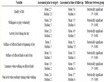
Table 1. Dependence of the pipe period on the distance in the light between them.
- a foundation with an angle of coverage , while the height of the foundation from the ground to the bottom point of the pipe was assumed to be 0.2D. In addition, support was considered on a flat base.
As can be seen from Figure 16, the largest value of  corresponds to support on the foundation, and the smallest on the base with a coverage angle of
 . For example, at
 , the value of
  for pipes supporting

Figure 15. Diagrams of radial soil pressure on pipes of a two-thread styling.

Figure 16. Graphs of the dependence of the maximum ground pressure (vmax) on the pipes from the distance in the light (d) between the strands (Н = 6 m, D = 2 mм, γ = 16.7 кг/m3, v = 0.2).
the foundation is larger than the corresponding values for pipes that support a flat solid base by 3%. solid base with an angle of coverage  by 6%, the base with an angle of coverage
  by 8%. This phenomenon is explained by the fact that the larger the I pipe protrudes above the surface of the base (together with the foundation). The more the pressure of the soil acting on this pipe is concentrated. We also note that, regardless of the type of support, the quantity
  decreases with increasing coefficient υ. With an increase in the coefficient υ by a factor of 4,
  decreases depending on the type of support of the pipe in 1.17 - 1.21 times. Given the slight change in
 , depending on the method of support (2% - 8%) in designing pipes based on a solid base, this factor can be ignored.
Table 2 shows the dependence of the coefficient of maximum vertical soil pressure ( ,
, maximum embankment height) on reinforced concrete pipes from the number of threads and the profile of the embankment. The pipes are supported by a reinforced concrete foundation with an angle of coverage up to 120˚. The wall thickness of the pipes is 0.1D.
The distance in the light between the pipes is 0.5D. Pipes are made of concrete of class B 25; n = 0.15; E = 30,000 MPa; soil of the mound with elastic constants n = 0.3; E = 30 MPa.
In the first row, Table 2 shows the results for long pipes laid over a bulk of constant height (flat deformation). In the second row, Table 2 shows the results for long pipes laid under the mound with the applied length of pipes laid under the mound with a variable longitudinal profile in the form of a triangle with an angle slope β = up to 30˚.
From Table 2 it follows that the coefficient  decreases with the number of threads. And this fact is true both for a flat problem (the first line) and for a volume one (second line).
For example, the value of  for an average three-threaded pipe (n = 3) is 35% smaller than the corresponding value for a single pipe (n = 1) in the case of a flat problem (
 ), and by 37%, in the case of spatial problem (30˚).
To analyze the influence of the longitudinal relief of the embankment on the soil pressure on the pipes and compare the results of the planar and spatial problems, the maximum height of the embankment ( ) was assumed equal to the height of the mound of constant height (
 ). From Table 2, the values in the first line differ from the corresponding values of the second row by an average of 30%. From this it follows that taking into account the variable length of the embankment height along the length of the pipe reduces the estimated ground
Table 2. Dependence of the coefficient Kmax on the number of threads and the angle of the longitudinal profile of the mound.
Table 3. Dependence of the coefficient Kmax on the length of the pipes l.
pressure as compared with the calculation performed on the flat-deformed scheme. This effect was obtained for the first time.
In this case, as follows from Table 1 this effect is slightly less pronounced for a single pipe (29%) and slightly stronger for two-thread (32%) and three-thread (30%) stacking pipes.
Influence of length of pipes. Table 3 shows the dependence of the coefficient Kmax for reinforced concrete pipes of two-strand packing from their length l ( ).
).
From Table 3 it follows that with a decrease in pipe length the coefficient Kmax kills. In this case, when the length , its effect on Kmax is insignificant. Thus, the length
  is that boundary of applicability of the plane theory of elasticity (plane deformation) for extended pipelines at a constant height of the embankment. In the work [20] the concept of the “core”, which in our case is equal to 10.0D, is derived, and is the boundary between the “short” and “length” pipes, i.e. at
 , the plane-deformed scheme gives an overestimate of the
  coefficient even at a constant height of the embankment. This overestimate is 38% at
  and 55% at
 .
.
Thus, taking into account the length of the pipes reduces the design ground pressure in comparison with the calculation using a flat-deformed scheme, if .
.
5. Conclusions
1) The maximum static pressure of the soil ( ) per pipe is somewhat less than that of a single pipe, an average of 10% for the outer pipe and 20% for the middle pipe. In this case, the quantity c
  increases with increasing parameter d, having a minimum at d = 0 (tubes stacked closely) and a maximum at d = 3.0, which coincides with the corresponding value for a single tube.
2) The pressure  decreases with increasing Poisson’s ratio
  of the soil. The greatest value of
  corresponds to supporting on the foundation, and the smallest to a profiled base with a large angle of coverage. Pressure
  on the outer tube and on the middle pipe is practically independent of the number of threads.
3) The horizontal static pressure ( ) of the soil located between the pipes decreases with increasing parameter d, reaching a minimum at
 , equals to the corresponding value for a single pipe. The horizontal pressure of the soil (
 ) on the outermost pipe from the opposite side of the adjacent pipe is equal to the horizontal pressure on a single pipe and does not depend on the parameter d. With a pipe spacing of
 , the value of
  28% is more than
 . The values of
  and
and  increase directly in proportion to the height of the embankment and decrease with decreasing Poisson’s ratio of the soil.
4) Diagrams of the radial and tangential static pressure of the soil for the outer tubes of multiline stacking ( ) and double-laying pipes practically coincide. The diagrams of the radial soil pressure are asymmetric for the outer tubes, and are practically symmetrical for the middle ones. The angle of this deviation depends on the parameter d and at
  which varies respectively from 15˚ to 0˚.
5) The values of the maximum radial and horizontal pressure of the soil on a single pipe, obtained in accordance with the [21] and the FEM for an extended embankment, having a constant height (flat deformation) are in good agreement. This gives grounds for using FEM to calculate multicell pipes in the design practice.
6) The account of the variable along the length of the pipe of the height of the embankment reduces the design ground pressure as compared with the calculation performed on the flat-deformed scheme. This effect is more pronounced for multi-threaded pipes and weaker for a single pipe [22] .
7) Allowance for the length of the pipes reduces the estimated ground pressure as compared with the calculation using a flat-deformed scheme, if their length is  [23] .
Cite this paper
Safarov, I.I. (2018) Numerical Modeled Static Stress-Deformed State of Parallel Pipes in the Deformable Environment. Open Access Library Journal, 5: e4671. https://doi.org/10.4236/oalib.1104671
References
- 1. Avliyakulov, N.N. and Safarov, I.I. (2007) Modern Problems of Statics and Dynamics of Underground Pipelines. Science and Tech-nology, Tashkent, 306 p.
- 2. Agapkin, V.M., Borisov, S.N. and Krivoshein, B.L. (1987) Reference Guide for the Calculation of Pipelines. Nedra, Moscow, 190 p.
- 3. Ainbinder, A.B. and Kamershtein, A.G. (1982) Calculation of Trunk Pipelines for Strength and Stability. Nedra, Moscow, 343 p.
- 4. Aleshin, V.V., et al. (2003) Numerical Analysis of the Strength of Underground Pipelines. URSS, Moscow, 320 p.
- 5. Borodavkin, P.P. and Sinyukov, A.M. (1984) Strength of the Main Pipelines. Nedra, Moscow, 245 p.
- 6. Erzhanov, N.S., Aitaliev, J.M. and Masanov, Z.K. (1980) Seismic Stress of Underground Structures in an Anisotropic Massif. Science, Alma-Ata, 211 р.
- 7. Kamershtein, A.G., Rozhdestvenskiy, V.V. and Ruchimsky, M.N. (1963) Calculation of Pipelines for Strength: A Reference Book. House Gostoptekhizdat, Moscow, 424 p.
- 8. Zenkevich, O. (1975) Finite Element Method in Engineering. Mir, Moscow, 623 р.
- 9. Lee, S.H. (2006) Application of the Perfectly Matched Layers for Seismic Soil-Structure Interaction Analysis in the Time Domain. University of Hawaii, Manoa.
- 10. Samarsky, A.A. (2005) Mathematical Modeling: Ideas, Methods, Examples. Fizmatlit, Moscow, 316 p.
- 11. Seleznev, V.Y., Aleshin, V.V. and Pryalov, S.N. (2005) Fundamentals of Numerical Simulation of Main Pipelines. KomKniga, Moscow, 496 p.
- 12. Postnov, V.A. and Kharkhur, I.Y. (1974) The Finite Element Method in Calculations of Ship Structures. Science, Leningrad, 342 р.
- 13. Vinogradov, S.V. (1980) Calculation of Underground Pipelines for External Loads. Stroiizdat, Moscow, 135 p.
- 14. Prisekin, V.A. and Rostorguev, G.I. (2010) The Basis of the Finite Element Method in the Mechanics of Deformable Bodies. Novosibirsk University Press, Novosibirsk, 238 p.
- 15. Safarov, I.I. and Auliyakulov, N.N. (2005) Methods of Increasing the Seismic Resistance of Underground Plastic Pipelines. Uzbek Journal of Oil and Gas, No. 44S, 42-44.
- 16. Seleznev, V.Y., Aleshin, V.V. and Klishin, G.S. (2002) Methods and Technologies of Numerical Simulation Gas Pipeline Systems. Publishing House of the URSS, Moscow, 448 p.
- 17. Seleznev, V.Ye., Aleshin, V.V. and Pryalov, S.N. (2009) Mathematical Modeling of the Main Pipeline Systems. Additional Chapters. MAKS Press, Moscow, 356 p.
- 18. Chichelov, V.A., et al. (2006) Calculations of the Stress-Strain State of Pipelines Operated under Difficult Conditions in a Nonlinear Setting. Gazprom, Moscow, 80 р.
- 19. Shammazov, A.M., et al. (2004) Development of a Method for Calculating the Stress-Strain State of Gas Pipelines Laid in Complex Engineering-Geological Conditions. Oil and Gas, 2, 119-128.
- 20. Safarov, I.I., Teshaev, M.K. and Boltayev, Z.I. (2016) Propagation of Linear Waves in Extended Lamellar Bodies. Lambert Academic Publishing, Saarbrücken, 315 p.
- 21. Safarov, I.I., Teshaev, M.H. and Boltaev, Z.I. (2012) Wave Processes in Mechanical Waveguide. Lambert Academic Publishing, Saarbrücken, 217 p.
- 22. Bozorov, M.B., Safarov, I.I. and Shokin, Y.I. (1966) Numerical Simulation of Vibra-tions, Dissipative Homogeneous and Heterogeneous Mechanical Systems. Science, Moscow, 188 p.
- 23. Safarov, I.I. (1992) Oscillations and Waves in Dissipatively Underbred Environments and Structures. Science, Tashkent, 250 p.