 Wireless Sensor Network, 2009, 1, 324-333 doi:10.4236/wsn.2009.14040 Published Online November 2009 (http://www.scirp.org/journal/wsn). Copyright © 2009 SciRes. WSN H-TOSSIM: Extending TOSSIM with Physical Nodes* Wenjun LI1, Xiaobin ZHANG2, Weihua TAN2, Xiaocong ZHOU2 1School of Software, Sun Yat-sen University, Guangzhou, Ch ina 2School of Info rmat ion Science and Techn ology, Sun Yat-sen University, Gua ngz hou, China Email: lnslwj@mail.sysu.edu.cn Abstract As the development of Wireless Sensor Network (WSN), software testing for WSN-based applications be- comes more and more important. Simulation testing is an important approach to WSN-based software testing, and TOSSIM is the most widely used simulation testing tool targeted at TinyOS which is the most popular operating system nowadays. However, simulation testing tools such as TOSSIM can not reveal program er- rors about communication detail or timing, and lack accurate power consumption model and even can not support power consumption estimation. In this paper, a hybrid testbed H-TOSSIM is proposed, which ex- tends TOSSIM with physical nodes. H-TOSSIM uses three physical nodes, of which, one shares the simu- lated environment with all virtual nodes to test the WSN program, and the other two bridge the real world and the simulated environment. H-TOSSIM combines the advantages of both the simulation in physical node and the simulation testing tools in WSN software testing. Through experiments, we show that H-TOSSIM really reveals program errors which the pure simulation testing can not capture, and can support power con- sumption estimation for large WSN with high accuracy and low hardware cost. Keywords: Wireless Sensor Network, Sink, Principal Node, Superior Node, Network Lifetime 1. Introduction 1.1. Background Recent advances in electronic technology and the need of practical applications enable the rapid development of Wireless Sensor Network (WSN), which consists of many resource-limited sensor nodes, and can monitor the phenomena in the physical world. WSN can be applied in military surveillance, environmental monitoring, health diagnostics, home automation, etc [1]. One of the primary challenges in the researches on WSN is software testing. A sensor network is self-configuration, and its nodes are low-power embedded devices, which make its software testing challenging. Simulation testing and hardware-in-the-loop (HIL) testing are the main approaches to W SN software testing. There exist many simulation tools for sensor networks. In simulation testing, the sensor network environment is simulated through pure PC software, which is controlla- ble, convenient and low-cost. HIL testing is one kind of important means for embedded software testing. Com- monly, HIL testing tools for WSN consist of dozens of physical sensor nodes. In HIL testing, the program under test runs in the physical sensor nodes with some assistant middleware. Compared with simulation testing, HIL testing can reveal more defects; however, it is high-cost and not so convenient. TOSSIM [2–4] is one of the most widely used simu- lators for WSN, which is designed for TinyOS [5–7] programs. TinyOS is the most popular operating system for WSN nowadays, which supports almost all popular sensor nodes; and its latest release is TinyOS 2.x, which is corresponding to TOSSIM 2.x. In this paper, only TOSSIM 2.x instead of TOSSIM 1.x is considered. TinyOS is component-based and event-driven, and TOSSIM simulates the sensor network through r eplacing some low-level components and introducing a discrete event queue. As a TinyOS WSN simulator, TOSSIM is accurate and scalable. With its help, developer can test the program before TinyOS application is deployed. 1.2. Motivation Simulation testing tools such as TOSSIM have some problems in WSN software testing. Firstly, they are dif- ficult to reveal program defects and faults related with communication details or timing. Secondly, they are hard *Supported by the National Natural Science Foundationof China under Grant No. 60673050.  W. J. LI ET AL 325 to include an accurate power consumption model. And these problems are mainly caused by pure software simulation. Taking TOSSIM as the representative, it has the fol- lowing defects and inadequacy. The first is that TOSSIM can not reveal length setting error of message sending . In a TinyOS program, message sending is a common opera- tion, and when sending a message, its length must be set correctly. However, even if the length of a message is set to be less than its intended size, TOSSIM can not reveal this fault when testing the program. Yet exceptions will occur for such program to run in the physical sensor network because messages will be partly lost. The second is that TOSSIM can not reveal task calcu- lation overload problem. Task is a deferred procedure call in TinyOS, which is used to complete some calcula- tion. For example, a TinyOS program sends a message every 100 ms, and posts a task which includes 200 thou- sands multiplication before each sending. In the simula- tion testing of TOSSIM, such program works fine. However, when running in the physical sensor network, the task calculation overload problem will occur: the number of messages a node sends per second is much less than the expectation (about 10 messages, in this case). There is also an inadequacy in TOSSIM; it does not support the power consumption estimation of sensor nodes, which is an important issue in WSN software testing because most sensor nodes are power-limited. Though PowerTOSSIM [8], a pure software extension to TOSSIM, can estimate the power consumption of sensor node, yet it is not so accurate and supports only one kind of sensor node. HIL testing can also estimate the power consumption of sensor nodes through digital multimeter; however, its hardware cost is too high because it needs dozens of physical sensor nodes.The problems existing in the simulation testing tools such as TOSSIM impede the comprehensive testing for WSN software, which may increase the cost of the application development. And these problems are difficult to solve by pure software extension. 2. Related Work There exist many testing tools dedicated to WSN soft- ware testing. In the following discussion, ns-2 [9], Sen- sorSim [10], EmTOS [11], PowerTOSSIM, AMETU [12] and avrora [13] belong to simulation testing tools; TO- SHILT [14], MoteLab [15] and DSN [16] belong to HIL testbed. Ns-2 is a universal network simulator which has been popular for many years. SensorSim is an extension to ns-2, which integrates some WSN features. Both ns-2 and SensorSim can not support TinyOS program di- rectly. EmTOS is an extension to EmSim [17] which is de- signed for EmStar [17], another WSN operating system. EmTOS can simulate heterogeneous WSN, which sup- ports both EmStar and TinyOS programs. PowerTOS- SIM is an extension to TOSSIM, and sup ports the power consumption estimation of the node; however, its error rate can be up to 13% and it supports only one kind of sensor node. AMETU and avrora are both fine-grained TinyOS program simulators, and they both simulate the WSN in instruction level. The differences between them are mainly the synchronization strategy for different nodes. Because of the simplification of the network layer, these simulators are difficult to reveal program faults related to communication details. And they also can not reveal program faults related to timing since they do not model the practical capability of sensor nodes. TOSHILT, MoteLab, and DSN are HIL testbeds, all of which consist of dozens of physical sensor nodes. The differences of them are mainly the connection type be- tween sensor nodes and the console. All of them can re- veal more faults than simulation testing; however, their hardware cost is too high and they are not convenient when testin g WS N programs. 3. Proposed Solution As discussed above, pure software extension is not the solution to solve the problems existing in simulation testing tools such as TOSSIM. Instead, physical nodes are considered here because they are the target platforms for WSN software and may capture more problems. So, the solution which combines the physical nodes and the simulated environment is proposed in this paper. This solution is called H-TOSSIM, which extends TOSSIM with physical nodes. In H-TOSSIM, not all TinyOS pro- grams run in the physical nodes, because that costs too much and is inconvenient. H-TOSSIM is a hybrid testbed. In fact, there will be just only one physical node in the Physical node Virtual node Figure 1. An example of the tested WSN topology in H-TOSSIM. C opyright © 2009 SciRes. WSN  326 W. J. LI ET AL tested WSN topology of H-TOSSIM, and others are all virtual nodes. The only physical node can be configured to be a neighbor of any virtual node. As shown in Figure 1, in H-TOSSIM, one physical node interacts with other virtual nodes so as to test the TinyOS program, and all nodes run the same program. So the potential faults which pure simulation testing tools can not reveal will be captured through the interaction between the physical node and other virtual nodes. Another advantage of H-TOSSIM is that the power consumption of a node in a large WSN can be estimated through digital multimeter with low hardware cost. In H-TOSSIM testbed, the physical node runs in the real world, and the virtual nodes run in the simulated environment of PC, so two extra physical nodes are needed as dual base stations to bridge the physical node and the virtual nodes. It means that H-TOSSIM totally needs three physical nodes. 4. Design of H-TOSSIM 4.1. Overview of the Architecture Figure 2 shows the overview of the architecture of H-TOSSIM, which consists of a PN, a pair of DBS, two SFs, an MTTS, an ESECT and a GNB. PN is a physical sensor node which runs the TinyOS application under test. DBS consists of two base stations, which bridges the PN and the PC side of H-TOSSIM. SF is a tool provided by TinyOS to support serial communication, of which, one end connects the serial port and communicates with one of the DBS, and the other end may communicate with any PC program through socket. MTTS provides the services of messages transformation and transfer, and its both ends are separately two SFs and ESECT. ESECT is an extension to TOSSIM which aims to implement the Figure 2. The architecture of H-TOSSIM. synchronized execution and communication for the vir- tual nodes with the only physical node. ESECT includes five parts: the modification of TOSSIM, a driver, a re- ceiver, a sender, and a GNB sender. GNB is a graphical network browser, which displays the network interaction situation in a GUI (Graphical User Interface). In the following of this section, DBS, MTTS, ESECT and GNB will be introduced in detail. PN will be referred in the design of DBS. And since SF is a tool from TinyOS, it is discussed briefly in the design of MTTS. 4.2. DBS DBS is mainly used to tran sfer the messages between PN and the serial communication. Herein, we first explain why DBS but not single BS is used. There are two rea- sons. The first reason is to make messages sending from the virtual nodes to PN become concurrent. In H-TOSSIM, PN may have several virtual neighbors; however, all messages sent from the virtual nodes to PN are serialized in ESECT. Yet if we want to finds out more program faults through PN, we should test the case that PN receives messages concurrently. So DBS is adopted. With DBS, messages sent in high rate from the virtual nodes will be forwarded to each of the DBS al- ternatively, which will bring concurrency because of the relatively low-speed DBS. The second reason is that wireless radio rate is ap- proximately as twice as serial rate. There are many kinds of physical sensor nodes, and the radio rates of some of them can be up to 250 Kbps [18,19]. However, the BS connects with the PC through serial communication, of which the rate is just up to 115 Kbps. When PN sends messages in a high rate, there will be blocking between the BS and PC if only one single BS is us ed. That is why DBS is used in H-TOSSIM. With DBS, the transfer rate between PN and PC can be up to 230 Kbps, which is high enough because the serial messages are usually shorter than the corresponding radio messages. DBS physically consists of two BS’s; however, it is not the simple combination of two BS’s in software. The main differences between DBS and BS are re- flected on the direction from PN to PC. In the direction from PC to PN, each of the DBS transfers every mes- sage received from serial to radio. However, in the other direction, each of the DBS only transfers half of the messages it receives from PN, and drops every message from the other BS. In order to make each of the DBS transfer half of the messages from PN, every mess age sen t from PN is flagged to designate which of the DBS should deal with it. In H-TOSSIM, the source field of the message is chosen as the location of the flag because it can be retrieved in ESECT. The work of flag setting is done by a modified low component of TinyOS in PN, and the tested. Copyright © 2009 SciRes. WSN 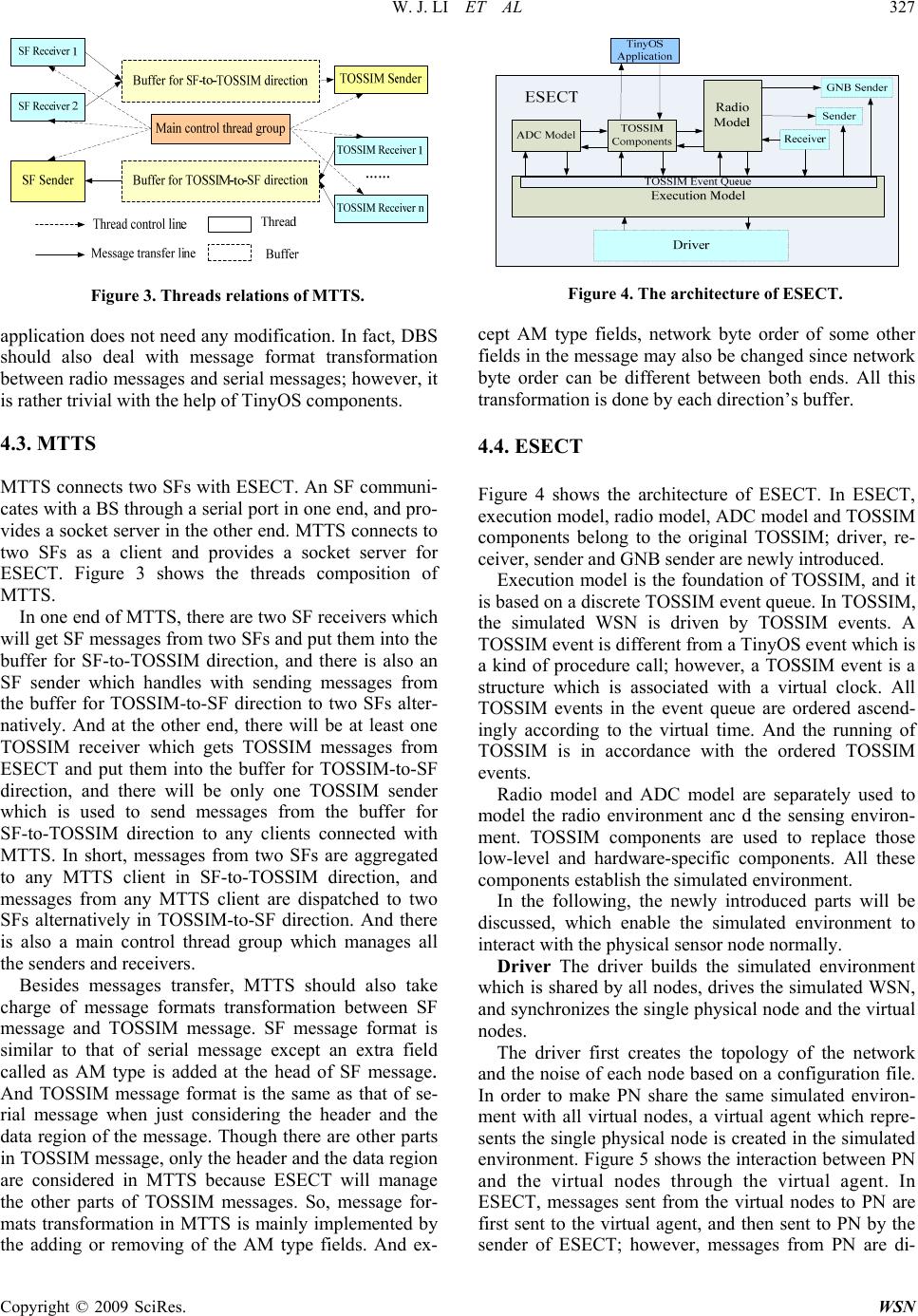 W. J. LI ET AL 327 Figure 3. Threads relations of MTTS. application does not need any modification. In fact, DBS should also deal with message format transformation between radio messages and serial messages; however, it is rather trivial with the help of TinyOS components. 4.3. MTTS MTTS connects two SFs with ESECT. An SF communi- cates with a BS through a serial port in one end, and pro- vides a socket server in the other end. MTTS connects to two SFs as a client and provides a socket server for ESECT. Figure 3 shows the threads composition of MTTS. In one end of MTTS, there are two SF receivers which will get SF messages from two SFs and put them into the buffer for SF-to-TOSSIM direction, and there is also an SF sender which handles with sending messages from the buffer for TOSSIM-to-SF direction to two SFs alter- natively. And at the other end, there will be at least one TOSSIM receiver which gets TOSSIM messages from ESECT and put them into the buffer for TOSSIM-to-SF direction, and there will be only one TOSSIM sender which is used to send messages from the buffer for SF-to-TOSSIM direction to any clients connected with MTTS. In short, messages from two SFs are aggregated to any MTTS client in SF-to-TOSSIM direction, and messages from any MTTS client are dispatched to two SFs alternatively in TOSSIM-to-SF direction. And there is also a main control thread group which manages all the senders and receivers. Besides messages transfer, MTTS should also take charge of message formats transformation between SF message and TOSSIM message. SF message format is similar to that of serial message except an extra field called as AM type is added at the head of SF message. And TOSSIM message format is the same as that of se- rial message when just considering the header and the data region of the message. Though there are other parts in TOSSIM message, only the header and the data region are considered in MTTS because ESECT will manage the other parts of TOSSIM messages. So, message for- mats transformation in MTTS is mainly implemented by the adding or removing of the AM type fields. And ex- Figure 4. The architecture of ESECT. cept AM type fields, network byte order of some other fields in the message may also be changed since network byte order can be different between both ends. All this transformation is done by each direction’s buffer. 4.4. ESECT Figure 4 shows the architecture of ESECT. In ESECT, execution model, radio model, ADC model and TOSSIM components belong to the original TOSSIM; driver, re- ceiver, sender and GNB sender are newly introduced. Execution model is the foundation of TOSSIM, and it is based on a discrete TOSSIM event queue. In TOSSIM, the simulated WSN is driven by TOSSIM events. A TOSSIM event is different from a TinyOS event which is a kind of procedure call; however, a TOSSIM event is a structure which is associated with a virtual clock. All TOSSIM events in the event queue are ordered ascend- ingly according to the virtual time. And the running of TOSSIM is in accordance with the ordered TOSSIM events. Radio model and ADC model are separately used to model the radio environment anc d the sensing environ- ment. TOSSIM components are used to replace those low-level and hardware-specific components. All these components establish the simulated environment. In the following, the newly introduced parts will be discussed, which enable the simulated environment to interact with the physical sensor node normally. Driver The driver builds the simulated environment which is shared b y all nodes, dr ives the simulated WSN, and synchronizes the single physical node and the virtual nodes. The driver first creates the topology of the network and the noise of each nod e based on a configuration f ile. In order to make PN share the same simulated environ- ment with all virtual nodes, a virtual agent which repre- sents the single physical node is created in the simulated environment. Figure 5 shows the interaction between PN and the virtual nodes through the virtual agent. In ESECT, messages sent from the virtual nodes to PN are first sent to the virtual agent, and then sent to PN by the sender of ESECT; however, messages from PN are di- C opyright © 2009 SciRes. WSN 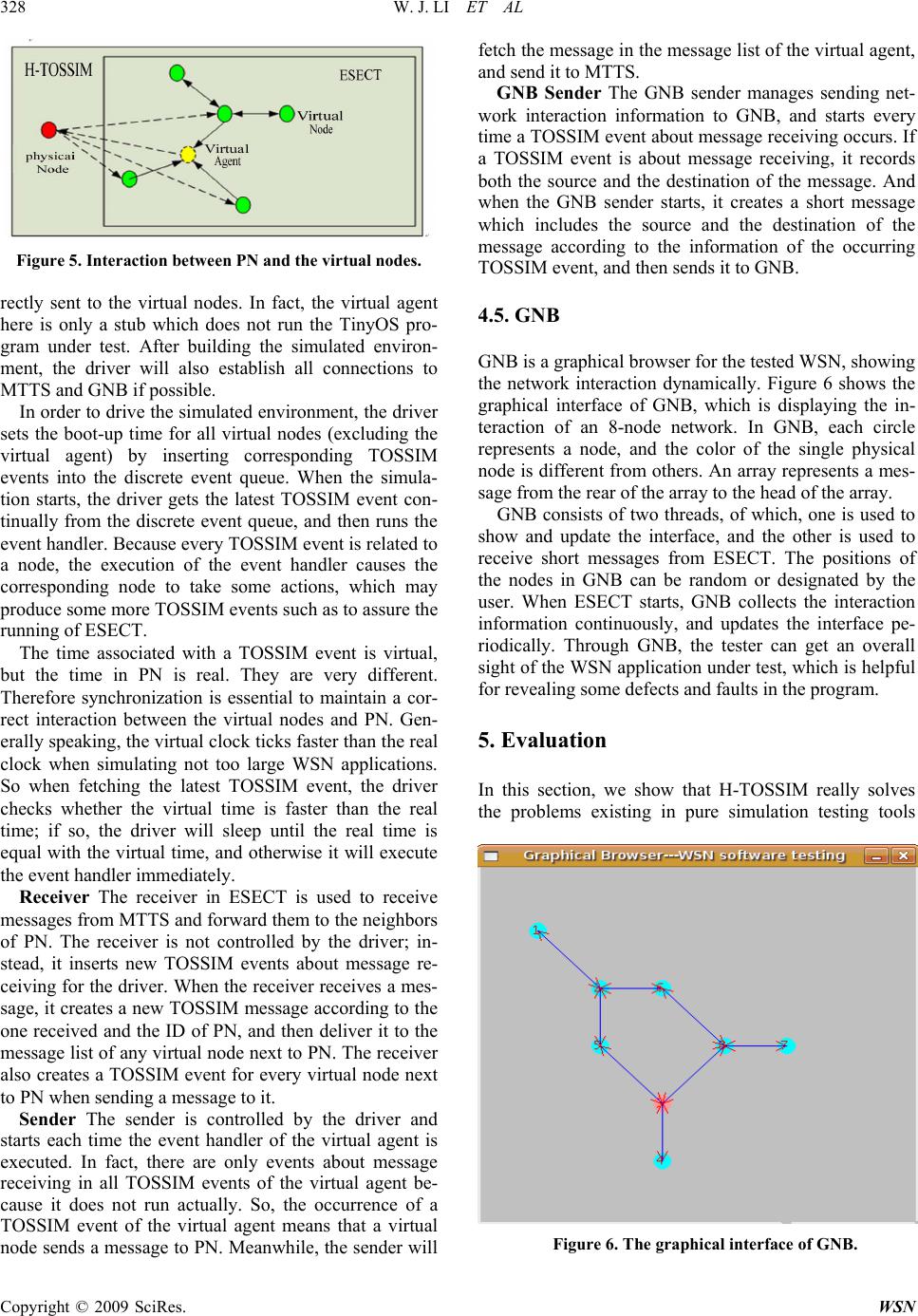 328 W. J. LI ET AL Figure 5. Interaction between PN and the virtual nodes. rectly sent to the virtual nodes. In fact, the virtual agent here is only a stub which does not run the TinyOS pro- gram under test. After building the simulated environ- ment, the driver will also establish all connections to MTTS and GNB if possible. In order to drive the simulated environment, the driver sets the boot-up time for all virtual nodes (excluding the virtual agent) by inserting corresponding TOSSIM events into the discrete event queue. When the simula- tion starts, the driver gets the latest TOSSIM event con- tinually from the discrete event queue, and then runs the event handler. Because every TOSSIM event is related to a node, the execution of the event handler causes the corresponding node to take some actions, which may produce some more TOSSIM events such as to assure the running of ESECT. The time associated with a TOSSIM event is virtual, but the time in PN is real. They are very different. Therefore synchronization is essential to maintain a cor- rect interaction between the virtual nodes and PN. Gen- erally speaking, the virtual clock ticks faster than the real clock when simulating not too large WSN applications. So when fetching the latest TOSSIM event, the driver checks whether the virtual time is faster than the real time; if so, the driver will sleep until the real time is equal with the virtual time, and otherwise it will execute the event handler immediately. Receiver The receiver in ESECT is used to receive messages from MTTS and forward them to the neighbors of PN. The receiver is not controlled by the driver; in- stead, it inserts new TOSSIM events about message re- ceiving for the driver. When the receiver receives a mes- sage, it creates a new TOSSIM message according to the one received and the ID of PN, and then deliver it to the message list of any virtual node next to PN. The receiver also creates a TOSSIM event for every virtual node next to PN when sending a message to it. Sender The sender is controlled by the driver and starts each time the event handler of the virtual agent is executed. In fact, there are only events about message receiving in all TOSSIM events of the virtual agent be- cause it does not run actually. So, the occurrence of a TOSSIM event of the virtual agent means that a virtual node sends a message to PN. Meanwhile, the sender will fetch the message in the message list of the virtual ag ent, and send it to MTTS. GNB Sender The GNB sender manages sending net- work interaction information to GNB, and starts every time a TOSSIM event about message receiving occurs. If a TOSSIM event is about message receiving, it records both the source and the destination of the message. And when the GNB sender starts, it creates a short message which includes the source and the destination of the message according to the information of the occurring TOSSIM event, and then sends it to GNB. 4.5. GNB GNB is a graphical brow ser for the tested WS N, sh ow ing the network interaction dynamically. Figure 6 shows the graphical interface of GNB, which is displaying the in- teraction of an 8-node network. In GNB, each circle represents a node, and the color of the single physical node is different from others. An array represents a mes- sage from the rear of the array to the head of the array. GNB consists of two threads, of which, one is used to show and update the interface, and the other is used to receive short messages from ESECT. The positions of the nodes in GNB can be random or designated by the user. When ESECT starts, GNB collects the interaction information continuously, and updates the interface pe- riodically. Through GNB, the tester can get an overall sight of the WSN application under test, which is helpful for revealing some defects and faults in the program. 5. Evaluation In this section, we show that H-TOSSIM really solves the problems existing in pure simulation testing tools Figure 6. The graphical interface of GNB. Copyright © 2009 SciRes. WSN  W. J. LI ET AL 329 Figure 7. The testbed of H-TOSSIM. such as TOSSIM. Figure 7 shows the testbed of H- TOSSIM. On the left, there is a laptop running two SFs, MTTS, ESECT, and GNB; in the center, there are three physical nodes, of which the two side-by-side nodes are used as DBS, and the remaining one is PN; on the right, there is a digital multimeter which is used to record the current of PN, and its result is saved to the desktop. The digital multimeter and the desktop are an option for es- timating the power consumption of PN. In the rest of this section, the applications under test we choose are typ ica l , which means: 1) they were de- veloped by the scholars who designed and implemented the TinyOS and TOSSIM, and distributed along with the TinyOS 2.x Package; 2) many researches on WSN test- ing also use these applications for evaluating their simu- lators. Besides, for better understanding of the advan- tages of H-TOSSIM against TOSSIM, comparisons of testing the same applicatio n are made. 5.1. Revealing the Length Setting Error of Mes- sage Sending In the nesC programming, before sending out a message via the radio, the code must explicitly depicts the length of the package. Hence it has a chance that the declared length and the actual length of the package are not cor- responding. In the real network, the radio component of a mote sends out the data according to the declared length, so the above case possibly leads to a incomplete pack age and unpredictable errors. However, TOSSIM, for the consideration of scalability, simulates the package send- ing by delivering a pointer to the package in the com- puter memory from the source node to the destination node, instead of the entire package, and this mechanism makes it can’t reveal the length setting error of message sending. H-TOSSIM has a physical network, which be- haves identical to any node in the real network, so it has the ability to reveal th is error. typedef nx_struct Ra- dioToBlinkMsg2 { nx_uint16_t nodeid; nx_uint8_t group; nx_uint8_t value; } RtoBGroupMsg_t; RtoBGroupMsg_t message typedef nx_struct Ra- dioToBlinkMsg { nx_uint16_t nodeid; nx_uint16_t counter; nx_uint8_t flag; } RtoBFlagMsg_t; RtoBFlagMsg_t message Figure 8. The structures of the two types. In the following experiments, the program called as RadioToBlink is tested. This program sends two types of messages periodically, and these two types are separately called as RtoBGroupMsg_t and RtoBFlagMsg_t. Figure8 shows the structures of the two types. RtoBGroupMsg_t message is 4 bytes, and RtoBFlagMsg_t message is 5 bytes In the two types of messages, the nodeid field is the source id of the message; the counter field is the value of a variable kept in the program which will increase by 1 whenev er a RtoBGroupMs g_t message is sent; the group field and the value field are separately the high byte and the low byte of the counter; the flag field is the value of the lowest 3 bits of the counter. We implant a fault in this program: the length of RtoBFlagMsg_t message is set to be 4 bytes when send- ing it out. In such a case, this type of message will be partly lost. We test the program in TOSSIM and H-TOSSIM. Figure 9 and 10 show the tested network topologies in TOSSIM and H-TOSSIM. Figure 11 and 12 give the testing results, which show the messages received by node 2. From Figure 11, it can be shown that all R to BFlagM sg _t messages received are normal. It means that TOSSIM can not reveal the length setting error of the program. However, from Figure 12, Figure 9. The tested network topology in TOSSIM. Figure 10. The tested netw ork topology in H-TOSSIM. C opyright © 2009 SciRes. WSN  330 W. J. LI ET AL Figure 11. The debugging information for RadioToBlink in TOSSIM. Figure 12. The debugging information for RadioToBlink in H-TOSSIM. we can see that the flag fields of RtoBFlagMsg_t mes- sages received from node 4 keep being 0, which means that the flag field is lost. That is to say, H-TOSSIM can reveal the length setting error through the comparison of PN and other virtual nodes. 5.2. Revealing Calculation Overload Problem in a Task In the real network, while the mote is processing a heavy task, it possibly ignores program interrupts because there is not enough CPU resource to handle the interrupt. Consequently, it leads some unexpected errors, such as loss of package. So the programmer needs to test whether his application will has a defect causing the mote into a calculation overload status. However, events in TOSSIM, by the mechanism of discrete event, are considered as completion in a snap in the simulated vir- tual environment. As a result, the calculation overload problem never occurs in TOSSIM. However, this situa- tion exists in the physical node of H-TOSSIM, which is helpful for the developer to find out his application’s defect. In the following experiments, the program called as BlinkToRadio will be tested. This program sends a BtoRFlagMsg_t message every T time, and posts a task to do some processing before each message sending. The structure of the BtoRFlagMsg_t message is the same with that of RtoBFlagMsg_t message. And the counter variable in the program will increase by 1 when sending a message. Here T is set to be 200 ms, and there is 300000 times multiplication in a task. We test this program in both TOSSIM and H-TOSSIM for 10 seconds. And each node is expected to send 50 messages totally. The testing network topologies in TOSSIM and H-TOSSIM are the same with that of the previous testing. Figure 13 and 14 give the testing results, which focus on the messages received by node 2. From Figure 13, it can be shown that the value of the counter field is ap- proximately 50 finally, which is as expected. However, this does not mean that the program is correct when it is Figure 13. The debugging information for BlinkToRadio in TOSSIM. Figure 14. The debugging information for BlinkToRadio in H-TOSSIM. Copyright © 2009 SciRes. WSN 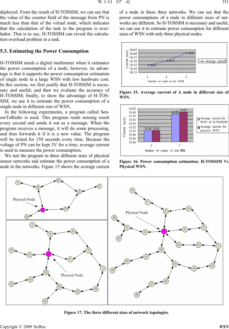 W. J. LI ET AL 331 Copyright © 2009 SciRes. WSN of a node in these three networks. We can see that the power consumptions of a node in different sizes of net- works are different. So H-TOSSIM is necessary and useful, we can use it to estimate power consumption for different sizes of WSN with only three physical nodes. deployed. From the result of H-TOSSIM, we can see that the value of the counter field of the message from PN is much less than that of the virtual node, which indicates that the calculation of the task in the program is over- laden. That is to say, H-TOSSIM can reveal the calcula- tion overload problem in a task. 5.3. Estimating the Power Consumption H-TOSSIM needs a digital multimeter when it estimates the power consumption of a node; however, its advan- tage is that it supports th e power consumption estimation of single node in a large WSN with low hardware cost. In this section, we first justify that H-TOSSIM is neces- sary and useful; and then we evaluate the accuracy of H-TOSSIM; finally, to show the advantage of H-TOS- SIM, we use it to estimate the power consumption of a single node in different size of WSN. Figure 15. Average current of A node in different size of WSN. In the following experiments, a program called Sen- sorToRadio is used. This program reads sensing result every second and sends it out as a message. When the program receives a message, it will do some processing, and then forwards it if it is a new value. The program will be tested for 150 seconds every time. Because the voltage of PN can be kept 3V for a time, average current is used to measure the power consumption. We test the program in three different sizes of physical sensor networks and estimate the power consumption of a node in the networks. Figure 15 shows the average current Figure 16. Power consumption estimation: H-TOSSIM Vs Physical WSN. Figure 17. The three different sizes of network topologies. 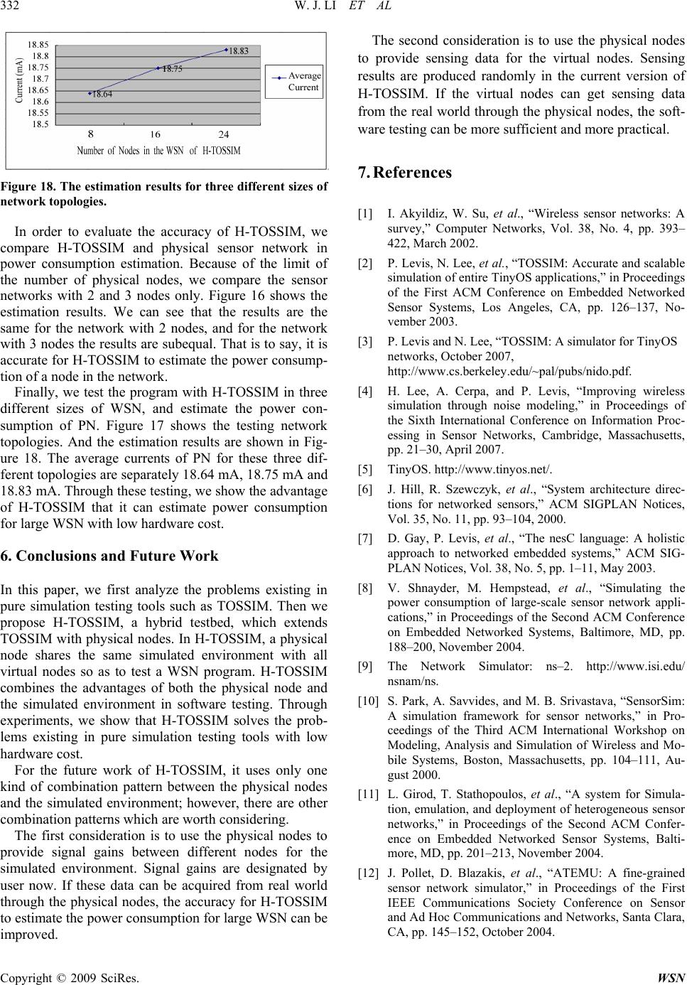 332 W. J. LI ET AL Figure 18. The estimation results for three different sizes of network topologie s. In order to evaluate the accuracy of H-TOSSIM, we compare H-TOSSIM and physical sensor network in power consumption estimation. Because of the limit of the number of physical nodes, we compare the sensor networks with 2 and 3 nodes only. Figure 16 shows the estimation results. We can see that the results are the same for the network with 2 nodes, and for the network with 3 nodes the results are subequal. That is to say, it is accurate for H-TOSSIM to estimate the power consump- tion of a node in the network. Finally, we test the program with H-TOSSIM in three different sizes of WSN, and estimate the power con- sumption of PN. Figure 17 shows the testing network topologies. And the estimation results are shown in Fig- ure 18. The average currents of PN for these three dif- ferent topologies are separately 18.64 mA, 18.75 mA and 18.83 mA. Through these testing, we show the advantage of H-TOSSIM that it can estimate power consumption for large WSN with low ha r d ware cost. 6. Conclusions and Future Work In this paper, we first analyze the problems existing in pure simulation testing tools such as TOSSIM. Then we propose H-TOSSIM, a hybrid testbed, which extends TOSSIM with physical nodes. In H-TOSSIM, a physical node shares the same simulated environment with all virtual nodes so as to test a WSN program. H-TOSSIM combines the advantages of both the physical node and the simulated environment in software testing. Through experiments, we show that H-TOSSIM solves the prob- lems existing in pure simulation testing tools with low hardware cost. For the future work of H-TOSSIM, it uses only one kind of combination pattern between the physical nodes and the simulated environment; however, there are other combination patterns which are worth considering. The first consideration is to use the physical nodes to provide signal gains between different nodes for the simulated environment. Signal gains are designated by user now. If these data can be acquired from real world through the physical nodes, the accuracy for H-TOSSIM to estimate the power consumption for large WSN can be improved. The second consideration is to use the physical nodes to provide sensing data for the virtual nodes. Sensing results are produced randomly in the current version of H-TOSSIM. If the virtual nodes can get sensing data from the real world through the physical nodes, the soft- ware testing can be more sufficient and more practical. 7. References [1] I. Akyildiz, W. Su, et al., “Wireless sensor networks: A survey,” Computer Networks, Vol. 38, No. 4, pp. 393– 422, March 2002. [2] P. Levis, N. Lee, et al., “TOSSIM: Accurate and scalable simulation of entire TinyOS applications,” in Proceedings of the First ACM Conference on Embedded Networked Sensor Systems, Los Angeles, CA, pp. 126–137, No- vember 2003. [3] P. Levis an d N. Lee, “TOSSIM: A simulator for TinyOS networks, October 2007, http://www.cs.berkeley.edu/~pal/pubs/nido.pdf. [4] H. Lee, A. Cerpa, and P. Levis, “Improving wireless simulation through noise modeling,” in Proceedings of the Sixth International Conference on Information Proc- essing in Sensor Networks, Cambridge, Massachusetts, pp. 21–30, April 2007. [5] TinyOS. http://www.tiny os. net/. [6] J. Hill, R. Szewczyk, et al., “System architecture direc- tions for networked sensors,” ACM SIGPLAN Notices, Vol. 35, No. 11, pp. 93–104, 2000. [7] D. Gay, P. Levis, et al., “The nesC language: A holistic approach to networked embedded systems,” ACM SIG- PLAN Notices, Vol. 38, No. 5, pp. 1–11, May 2003. [8] V. Shnayder, M. Hempstead, et al., “Simulating the power consumption of large-scale sensor network appli- cations,” in Proceedings of the Second ACM Conference on Embedded Networked Systems, Baltimore, MD, pp. 188–200, November 2004. [9] The Network Simulator: ns–2. http://www.isi.edu/ nsnam/ns. [10] S. Park, A. Savvides, and M. B. Srivastava, “SensorSim: A simulation framework for sensor networks,” in Pro- ceedings of the Third ACM International Workshop on Modeling, Analysis and Simulation of Wireless and Mo- bile Systems, Boston, Massachusetts, pp. 104–111, Au- gust 2000. [11] L. Girod, T. Stathopoulos, et al., “A system for Simula- tion, emulation, and deployment of heterogeneous sensor networks,” in Proceedings of the Second ACM Confer- ence on Embedded Networked Sensor Systems, Balti- more, MD, pp. 201–213, November 2004. [12] J. Pollet, D. Blazakis, et al., “ATEMU: A fine-grained sensor network simulator,” in Proceedings of the First IEEE Communications Society Conference on Sensor and Ad Hoc Communications and Networks, Santa Clara, CA, pp. 145–152, October 2004. Copyright © 2009 SciRes. WSN  W. J. LI ET AL 333 [13] B. L. Titzer, D. K. Lee, and J. Palsberg, “Avrora: Scal- able sensor network simulation with precise timing,” in Proceedings of the Fourth International Conference on Information Processing in Sensor Networks, Los Angeles, CA, pp. 477–482, April 2005. [14] D. Jia, G. H. Krogh, and C. Wong, “TOSHILT: Middle- ware for hardware-in-the-Loop testing of wireless sensor networks,” October 2007. http://www.ece.cmu.edu/~webk/sensor_networks/pub/ips n05_hilt.pdf. [15] G. Werner-Allen, P. Swieskowski, and M. Welsh, “Mo- teLab: A wireless sensor network testbed,” in Proceed- ings of the Fourth International Conference on Informa- tion Processing in Sensor Networks, Los Angeles, CA, pp. 483–488, April 2005. [16] M. Dyer, J. Beutel, et al., “Deployment support network: A toolkit for the development of WSNs,” in Proceedings of the Fourth European Workshop on Sensor Networks, Berlin, pp. 195–211, January 2007. [17] L. Girod, J. Elson et al., “EmStar: A software environ- ment for developing and deploying wireless sensor net- works,” in Proceedings of the USENIX Technical Con- ference, San Diego, CA, pp. 24–37, June 2004. [18] J. Hill, M. Horton, et al., “The platforms enabling wire- less sensor networks,” Communications of the ACM, Vol. 47, No. 6, pp. 41–46, June 2004. [19] J. Polastre, R. Szewczyk, and D. Culler, “Telos: Enabling ultra-low power wireless research,” in Proceedings of the Fourth International Conference on Information Process- ing in Sensor Networks, Los Angeles, CA, pp. 364–369, April 2005. C opyright © 2009 SciRes. WSN
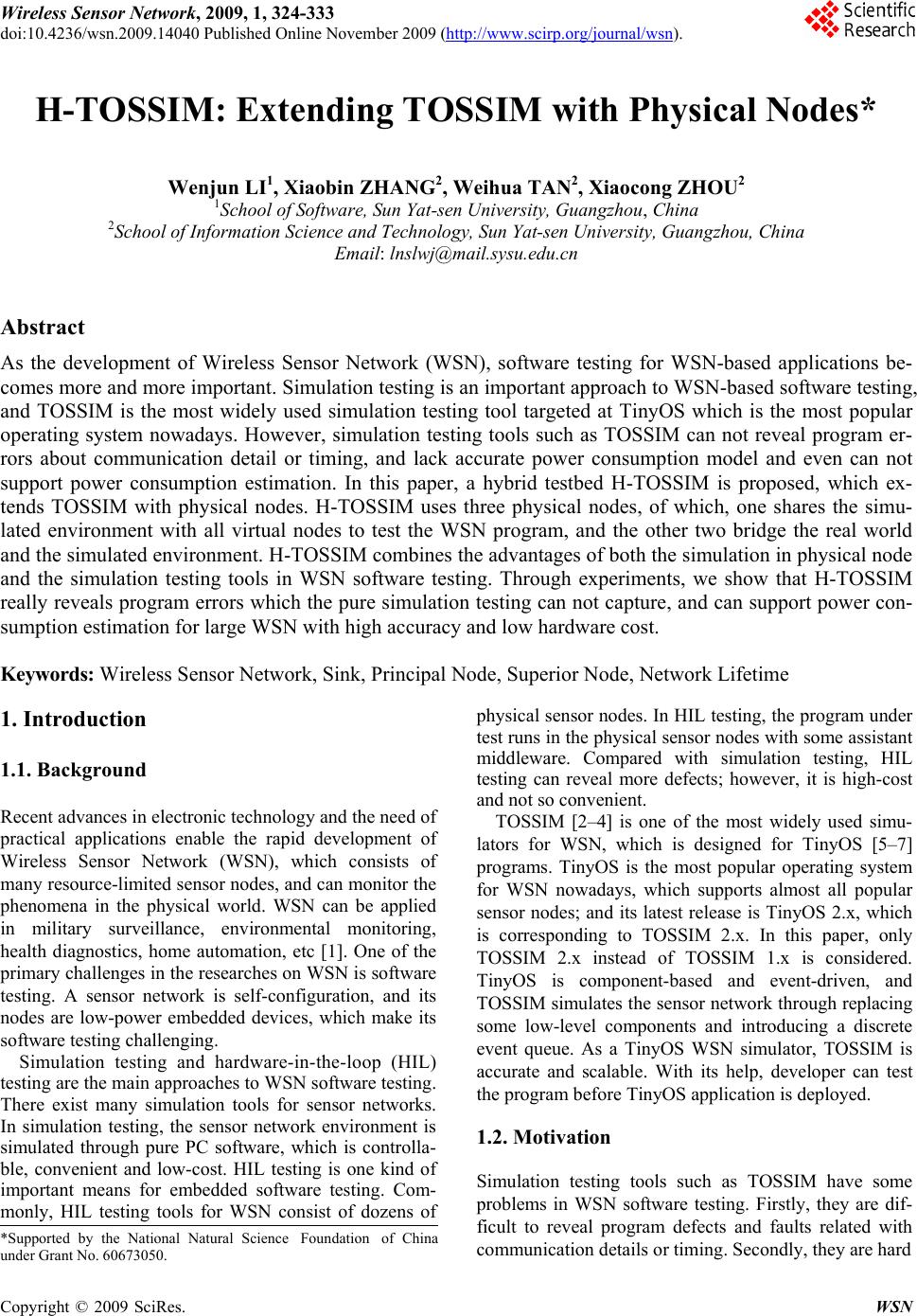
|