Paper Menu >>
Journal Menu >>
 Wireless Sensor Network, 2009, 1, 268-275 doi:10.4236/wsn.2009.14033 Published Online November 2009 (http://www.scirp.org/journal/wsn). Copyright © 2009 SciRes. WSN Performance Improvement of the DSRC System Using a Novel S and Π-Decision Demapper Jeich MAR, Chi-Cheng KUO Department of Communications Engineering, Yuan Ze University, Taiwan, China Email: eejmar@saturn.yzu.edu.tw Received March 31, 2009; revised June 20, 2009; accepted June 23, 2009 Abstract Based on the constellation diagram of the different modulations, a novel S and Π-decision rule is designed for the analog demapper of the orthogonal frequency-division multiplexing (OFDM) systems. The dedicated short-range communications (DSRC) system is chosen as an OFDM platform to compare the performance among the proposed S and Π-decision decoder, hard-decision and soft-decision decoders. Simulation results demonstrate that both the complexity and performance of S and Π-decision demapper used for M-ary quad- rature amplitude modulation (QAM) OFDM system can be greatly improved. The number of decisions be- tween the received symbol and constellation points can be simplified to look up table2 log M times for M-ary QAM OFDM system. Keywords: S and Π-decision Rule, Analog Demapper, DSRC System, OFDM 1. Introduction In the traditional digital communication system where the digital Viterbi decoder is used, the maximum likeli- hood decision rule is applied to both the demapper and digital hard-decision or soft-decision Viterbi decoder. The soft-decision decoder is the recommended scheme to be used in the digital Viterbi decoder because it provides a coding gain over the hard-decision decoder [1,2]. A simplified algorithm of the soft-decision Viterbi decoder for the 16-quadrature amplitude modulation (QAM) and 64-QAM constellations was presented in [3], which al- lows the complexity of the demapper to be maintained at almost the same level for all the possible modes of HIPERLAN/2. In [4], it presented that for M-ary QAM systems the complexity of the demapper in a soft-deci- sion Viterbi decoder used for bit-interleaved coded modulation can be significantly lowered without com- promising the performance. Four types of analog-input Viterbi decoders are described and compared in [5], where the analog-to-digital converter (A/D) converter is included as part of a digital Viterbi decoder. The analog circuit flaws of the previously used add-compare-select (ACS) chips are included in the comparison. It concludes the analog Viterbi decoder is able to outperform the digital Viterbi decoder, as well as achieve 3-bit or higher decoding resolution. In this paper, we propose a new S and Π-decision decoder, where the S and Π-decision rules are designed for the analog demapper of the or- thogonal frequency-division multiplexing (OFDM) sys- tems. The ACS and path memory (PM) modules, which are parts of the analog Viterbi decoder introduced in [6], are used to perform the Viterbi decoding process. The proposed S and Π-decision demapper combined with the digital Viterbi decoder is another alternative to using the S and Π-decision decoder. Because analog Viterbi de- coder outperforms digital Viterbi decoder and analog very-large-scale integration (VLSI) implementation is in general more area and power efficient than digital im- plementation, the performance comparison of the S and Π-decision decoder using the digital Viterbi decoder is not included in the paper. The dedicated short-range communications (DSRC) system [7], which employs OFDM technique, provides wireless communications over a short distance between the roadside and high-speed mobile radio units or be- tween high-speed vehicles. The DSRC system will work in a mobile environment with time-varying characteris- tics. The time-varying fading effect of the DSRC system may not be effectively compensated by using the long symbol training and pilot-based frequency synchronizer [8]. The combined interleaving and convolution coding, which provides the time diversity function, may further improve the performance of the DSRC system. We choose DSRC system as a basis for the performance  J. MAR ET AL. 269 comparison among different decoders. Based on the analog-input Viterbi decoder, the coding gain of the DSRC system achieved by replacing the hard-decision and soft-decision decoders with the proposed S and Π-decision decoder will be confirmed with the simula- tions. The rest of this paper is organized as follows. In Sec- tion II, several channel decoding schemes are described. The proposed S and Π-decision decoder is depicted in detail for the binary phase-shift keying (BPSK), quadra- ture phase-shift keying (QPSK), 16-QAM and 64-QAM OFDM signals of the DSRC systems. Section III briefly describes the base band model of the DSRC system, which is used to compare the bit error rate (BER) per- formance of the DSRC system for the different decoders. Simulation results are given in Section IV, which show the coding gain achieved by the proposed S and Π-decision decoder compared to the hard-decision and soft-decision decoders. Finally, conclusions are drawn in Section V. 2. S and Decision Decoder for the OFDM Systems In the traditional digital communication system, the digital Viterbi decoding uses a maximum likelihood rule which is ideal for an additive white Gaussian noise (AWGN) channel. For a hard-decision Viterbi decoder, the samples matching to a single bit of a code word are quantized to the two levels zero and one, a decision is made as whether each transmitted bit in a code word is zero or one. The coding gain of the soft-decision Viterbi decoder for the hard-decision Viterbi decoder in Rayleigh fading channel increases to about 2dB [1]. A four-level discrete symmetric channel model [2] is used for the soft-decision decoder. The demapper assigns one of four values to each received signal. The path metrics in the Viterbi algorithm are calculated by weighting the square of the Hamming distance between the soft-deci- sion and the reference value. The four-level soft-decision Viterbi decoder is almost exactly as shown for the hard- decision case with the only difference being the in- creased number of path metrics. The block diagram of the proposed S and Π-decision decoder for the OFDM system is shown in Figure 1, where it consists of a S and Π-demapper and an analog Viterbi decoder. The S and Π-decision decoder is a non- uniform infinite-level quantization decoder. The S and Π-decision demapper assigns an analog complex value to the analog Viterbi decoder for each received signal z(y) according to a combination of S and Π functions, as shown in Figure 2. The Π function [9], as shown in Fig- ure 2(a), is defined as follows: (();,/2,) () ((); ,) 1(();,/2,) () SzyM RM RMforzyM zy RMSzyMMR MRforzy M (1) where z(y) represents either or and y is the received signal after channel compensation. The con- stellation decoder estimate the mth symbol gained through the received signal after channel compensation, , can be found in the signal space diagrams [10] for BPSK, QPSK, 16-QAM and 64-QAM, respectively, where the values of ˆ() m Iy ˆ() m Qy ˆm ˆ ˆˆ () ()() mm m Yy Iy jQy () I y and are serially decoded according to the modulation type. The Π-function goes to zero at the points ˆ() m Qy () z yMR (2) while the Π-function goes to 0.5 at the crossover points () 2 R zyM (3) Notice the parameter R is now equal to one, which is the total width at the crossover points; parameter M is now equal to zero, which is the middle point of the Π-function. The S-function, as shown in Figure 2(b), is defined as follows: 2 2 0 () () 2() () (();,, )() 12() () 1 () for zy zy forz y Szy zy forz y for zy (4) For BPSK modulation, the value of ˆ() m I y is in the interval of (-1,1) of constellation diagram. From BPSK constellation diagram, the original one bit binary data (b0) is decided as using the S-decision rule. Using (4) for α=-1, β=0 and γ=1, the values of are produced as follows: =-1 for z(y)≦-1; =1 for z(y)1; ≧ =for -1<z(y)<1. 0 ˆ b 0 ˆ b 0 ˆ b 0 ˆ b )) y 0 ˆ b((Sz For QPSK, the values of ˆ() m I y (2) b and in the constellation diagram are found in the intervals (-1, 1). The original two-bit vector = (b0, b1) is also esti- mated using the S-function as a decision rule. The S-decision rule in (4) for α=-1, β=0 and γ=1 is used to determine from the received I-channel signal part ˆ() m Qy 0 ˆ b ˆ() m I y part ˆ and determine from the Q-channel signal 1 ˆ b () . m Qy Copyright © 2009 SciRes. WSN  270 J. MAR ET AL. Copyright © 2009 SciRes. WSN ˆ ˆ() ()Ix Qx ˆ()Qx ˆ()Ix () ˆ i b Figure 1. Block diagram of the S and Π-decision decoder. The constellation diagram of Fi 16-QAM is shown in 1 gure 3, where the values of ˆ() m I y and ˆ() m Qy for 16-QAM modulation are found intervals of (-3, -1, 1, 3), respectively. The message points in each quadrant are assigned with Gray-encoded four-bit vector (3) b the in = (b0 b1 b2 b3). The first two bits (b0 b1) and last twots (b2 b 3) in (3) b are transmitted in I and Q-channel, re- spectively. h first two bits (boldface) of the I-channel from left to right message points and last two bits (Nor- mal) of the Q-channel from bottom to top message points have the same 8-bit pattern 00 01 11 10 in Figure 3. The first four odd bits are 0 0 1 1 and the second four even bits are 0 1 1 0 can be estimated by using the S and Π'-decision rule, respectively, as shown in Figure 4. The Π'-decision rule as shown in Figure 4(a) is defined as 0()-3zy bi Bot ' (();-3,-2,-1)-3() -1 (()) 1-1() 1-(( );1,2,3)1( )3 0() Szy zy zy zy Szy zy zy 1 3 (5) where the S-function is defined in (4). The first two bits (0 ˆ b 1 ˆ b) and the last two bits (2 ˆ b 3 ˆ b) of the demapper ouufor each message point arestimated from the values of ˆ() m tp t e I y and ˆ() m Qy, respectively. The S-de- cision rule ed to ine 0 ˆ b and 2 ˆ b and the Π'-decision rule is used to determin 1 ˆ b an3 ˆ b. The number of decision needed to obtain Snd Π-decision demapper output in 16-QAM OFDM system is four. The same design principle of the S and Π-decision de is usdeterm ed a mapper used for 16-QAM is applied for 64-QAM. The values of ˆ() m I y and ˆ() m Qyin the constellation diagram for 64-QAM modulare found in the in- tervals of (-7, -5,-3, -1, 1, 3, 5, 7), respectively. Simi- larly, the six-bit vector (4) ˆ b = (0 ˆ b 1 ˆ b 2 ˆ b 3 ˆ b 4 ˆ b 5 ˆ b) ation for each message point of 64-QAM modulation is de Figure 2. (a) Π-decisionule; (b) S-decision rule. r Figure 3. The constellation diagram of 16-QAM. -3 -2 -10 1 23 0 0.5 1 -3 -2 -10 1 23 0 0.5 1 z(y) (a) '(()) z y (())Szy z(y) (b) 0101 Figure 4. (a) Π'-decision rule; (b) S-decision rule for 16-QAM. 0011 -1-0.8 -0.6 -0.4 -0.2 00.2 0.4 0.6 0.8 1 0 0.2 0.4 0.6 0.8 1 -1-0.8 -0.6 -0.4 -0.2 00.2 0.4 0.6 0.8 1 0 0.2 0.4 0.6 0.8 Π(x) S(x) x x ) ) (a (b -1-0.8 -0.6 -0.4 -0.2 00.2 0.4 0.6 0.8 1 0 0.2 0.4 0.6 0.8 1 1 0.8 -1-0.8 -0.6 -0.4 -0.2 00.2 0.4 0.6 0.8 1 0 0.2 0.4 0.6 Π(x) S(x) x x ) ) (a (b 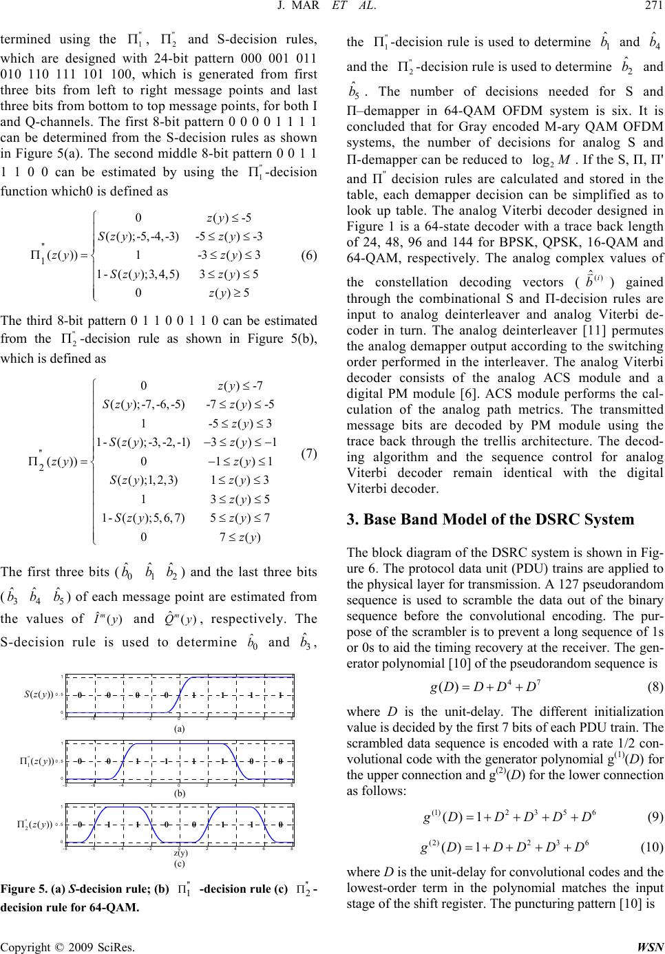 J. MAR ET AL. 271 termined using the , and S-decision rules, which are designed witt pattern 000 001 011 010 110 111 is generated from first three bits from left essage points and last three bits from bottotssage points, for both I and Q-channels. Tht pattern 0 0 0 0 1 1 1 1 can be determined frohsion rules as shown in Figure 5(a). The le 8-bit pattern 0 0 1 1 1 1 0 0 can be estimated b using the -decision function which0 is defined as 3 1 The first three bits () and the last three bits ) of each t are estimated from es of , respectively. The rulrmine and " 1 h 101 100, whi to ri m to e first m t second m " 2 24-bi ch ght m op me 8-bi e S-deci idd y" 1 '' 1 (();-5,-4,-3)-5()-3 (()) 1-3()3 1-( ();3,4,5)3()5 0()5 Szy zy zy zy Szy zy zy (6) The third 8-bit pattern 0 1 1 0 0 1 1 0 can be estimated from the " 2 -decision rule as shown in Figure 5(b), which is defined as 0 0()-5zy '' 2 ()-7 ((); -7, -6, -5)-7()-5 1-5() 1-((); -3, -2, -1)3()1 (()) 01() (();1,2,3)1() 3 13()5 zy Szy zy zy Szy zy zy zy Szy zy zy 1-(();5,6,7)5( )7 07() Szy zy zy (7) 0 ˆ b me () an use 1 ˆ b ssa d d t 2 ˆ b ge poin ˆm Qy o det (3 ˆ b th S-de 4 ˆ b e valu cisi 5 ˆ b on ˆm Iy e is () e0 ˆ b 3 ˆ b, -8 -6 -4 -2 0 2 4 6 8 0 0.5 1 -8 -6 -4 -2 0 2 4 6 8 0 0.5 1 -8 -6 -4 -2 0 2 4 6 8 0 0.5 1 (())Szy (a) (c) z(y) 0000 1111 Figure 5. (a) S-decision rule; (b) -decision rule (c) '' 1(())zy '' 2(())zy (b) 0101 1 010 0011 0011 '' 1 '' 2 - " 1 decision rule for 64-QAM. the -decision rule is used to determine and and t 1 ˆ b4 ˆ b he " 2 -decision rule is used to determ mber of decisions n n 64-QAM OFDM system that for Gray encoded M-ary QA systeme number of decisions for apper can be reduced to ine eeded for S and is si anal 2 ˆ b x. I M OFD og S and and t is M 5 ˆ b Π con Π . Th –dema clud s, -dem e nu pper i ed th 2 log M . If th ion rules are ca lapper decisisim e analog Vi 64-state decoderce bn n rb cod trics. e S, Π in ied as gned le , Π' the to in and ed and tab Fi Π'' gure 1 decis e, each dem look up table. Th is a lculated and s on can be terbi decoder with a tra alog com tored plif desi ack gth of 24, 48, 96 and 144 for BPSK, QPSK, 16-QAM 64-QAM, respectively. The aplex values of the constellation decoding vectors (() ˆi b) gain through the combinational S and Π-decision rules are input to analog deinterleaver and analog Vitei de- er in turn. The analog deinterleaver [11] permutes the analog demapper output according to the switching order performed in the interleaver. The analog Viterbi decoder consists of the analog ACS module and a digital PM module [6]. ACS module performs the cal- culation of the analog path meThe transmitted message bits are decoded by PM module using the trace back through the trellis architecture. The decod- ing algorithm and the sequence control for analog Viterbi decoder remain identical with the digital Viterbi decoder. 3. Base Band Model of the DSRC System The block diagram of the DSRC system is shown in Fig- ure 6. The protocol data unit (PDU) trains are applied to the physical layer for transmission. A 127 pseudorandom sequence is used to scramble the data out of the binary sequence before the convolutional encoding. The pur- pose of the scrambler is to prevent a long sequence of 1s or 0s to aid the timing recovery at the receiver. The gen- erator polynomial [10] of the pseudorandom sequence is 47 () g DDDD (8) where D is the unit-delay. The different initialization value is decided by the first 7 bits of each PDU train. The crambled data sesquence is encoded with a rate 1/2 con- tion volutional code with the generator polynomial g(1)(D) for he upper connection and g(2)(D) for the lower connect as follows: (1)2 35 6 ()1 g DDDDD (9) (2)2 3 6 ()1 g DDDDD (10) where D is the unit-delay for convolutional codes and the lowest-order term in the polynomial matches the input stage of the shift register. The puncturing pattern [10] is Copyright © 2009 SciRes. WSN 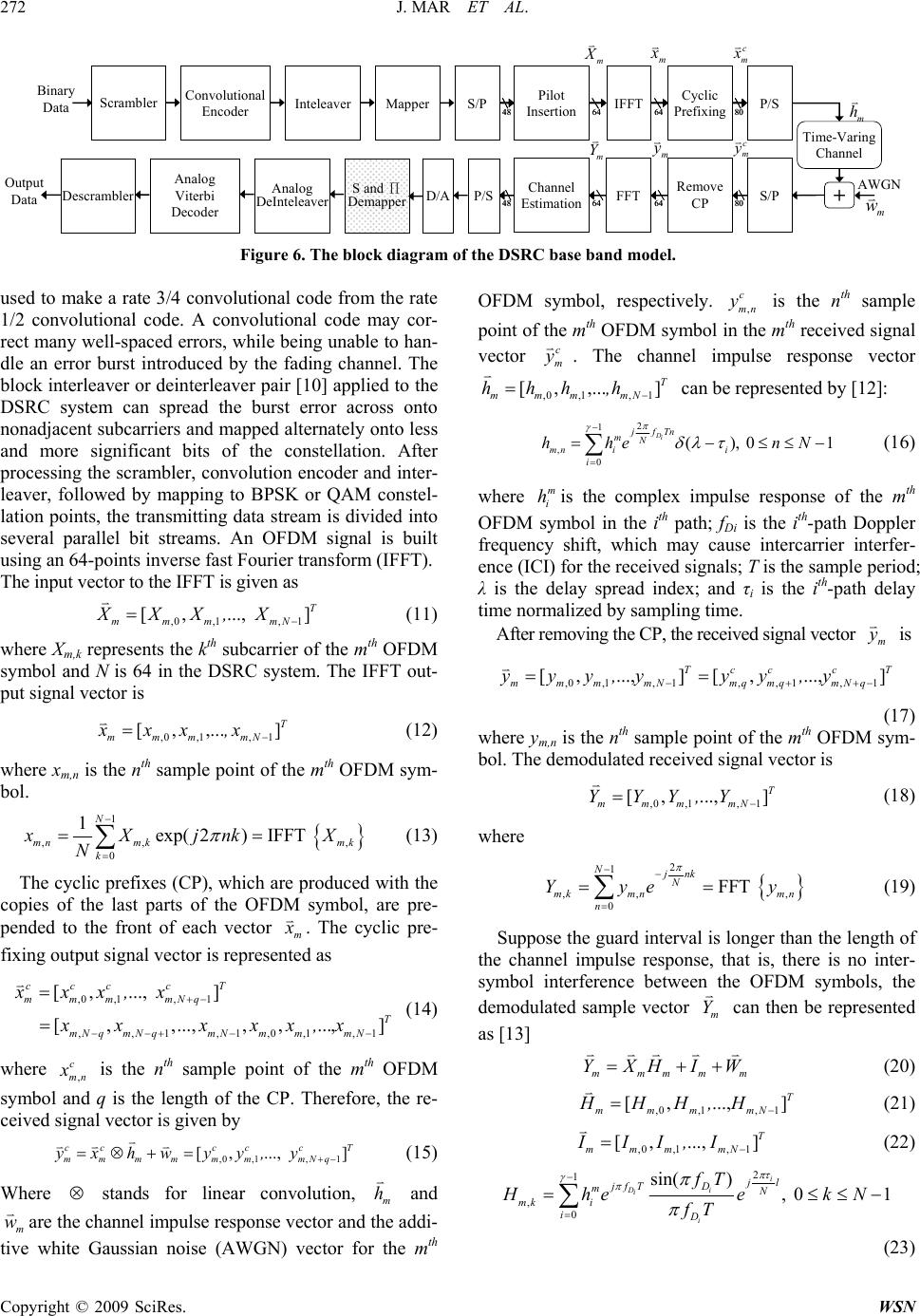 272 J. MAR ET AL. Copyright © 2009 SciRes. WSN Mapper S/P Pilot Insertion IFFT Cyclic Prefixing P/S P/S S/PFFT Remove CP Channel Estimation S and Π Demapper Time-Varing Channel + Binary Data O utpu t Data AWGN m X m x c m x m Y m y c m y m Convolutional h Scrambler Descrambl er Encoder Analog Viterbi Decoder Inteleaver Analog DeInteleaver D/A 48 64 6480 48 64 6480 m w 48 64 64 80 48 64 6480 Figure 6. The block diagram of the DSRC base band model. used to make a rate 3/4 convolutional code from the rate 1/2 convolutional code. A convolutional code may cor- rect many well-spaced errors, while being unable to han- dle an error burst introduced by the fading channel. The block interleaver or deinterleaver pair [10] applied to the DSRC system can spread the burst error across onto nonadjacent subcarriers and mapped alternately onto less and more significant bits of rocessing the scrambler, convolution encoder and inter- the constellation. After p leaver, followed by mapping to BPSK or QAM constel- lation points, the transmitting data stream is divided into several parallel bit streams. An OFDM signal is built using an 64-points inverse fast Fourier transform (IFFT). The input vector to the IFFT is given as ,0,1, 1 [ ,...,]T mmmmN XXX, X (11) where Xm,k represents the kth subcarrier of the mth OFDM symbol and N is 64 in the DSRC system. The IFFT out- put signal vector is ,0,1,1 [ , ,...]T mmmmN xxx, x (12) mth OFDM sym-where xm,n is the nth sample point of the bol. ,, , 0 exp(2)IFFT mn mkmk k xXjnkX N (13) The cyclic prefixes (CP), which are produced with the copies of the 1 1N last parts of the OFDM symbol, are pre- pended to the front of each vector m x . The cyclic pre- fixing ou put signal vector is represented as c m x t (14) w ,0 ,1,1 ,,1,1,0,1, [ ,...,] [,,...,,,..., ccc T mmmNq mN qmN qmNmmmN xx, x xx xxx,x 1 ]T here , c mn x is the nth sample point of the mth OFDM symbol and q is the length of the CP. Therefore, the re- ceived signal vector is given by ,0 ,1,1 [ ,..., cccc c mm m mmmmNq yxhwyy, y ] T (15) Where stands for linear convolution, m h and m w are the channel impulse response vector anaddi- tive white Gaussian noise (AWGN) vector for the mth OFDM symbol, respectively. d the , c mn y is the nth sample point of the mth OFDM symmth received signal vector bol in the c m y . The channel im response vector pulse ,0 ,,1, 1 [,... ]T mmm mN hhh,h can besented by [12]: repre 2 1 , 0 N mn i i hhe (), i 0 Di jfTn mnN 1 se i T and τi (16) ntercarrier interfer- ence (IChe received signals; is the sam λ spread index; is the ith- where s the complex impulse response of the mth OFDM symbol in the ith path; fDi is the ith-path Doppler frequency shift, which may cau m i hi I) for t is the delay mal ple period; path delay time norized by sampling time. After removing the CP, the received signal vector m y is ,0,1,1,,1,1 [,...,] [,...,] Tccc T mmmmNmqmqmNq yyy,yyy,y (17) where ym, is the nth sample point of the mth OFDM sym- bol. Thodulated received signal vector is ..., ]T ,Y n e dem ,0 ,1 [ , mm m YYY , 1 mN (18) where ,, , 0 FFT N mk mn mn n ye y (19) Suppose the guard interval is longer than the length of the channel impulse response, that is, there is no inter- symbol interference between the OFDM symbols, the demodulated sample vector m Y can 2 1 Njnk Y then be represented as mm W [13] mmm YXHI , ,,H (2) 0 ,0 ,11 [ ,...]T mmmmN HHH (21) ,0,1, 1 [ ,...,]T mmm mN III, I (22) 2 )N 1 , 0 sin( i Di i i jl jfT D m mki D fT Hhe e fT , 01kN i (23) 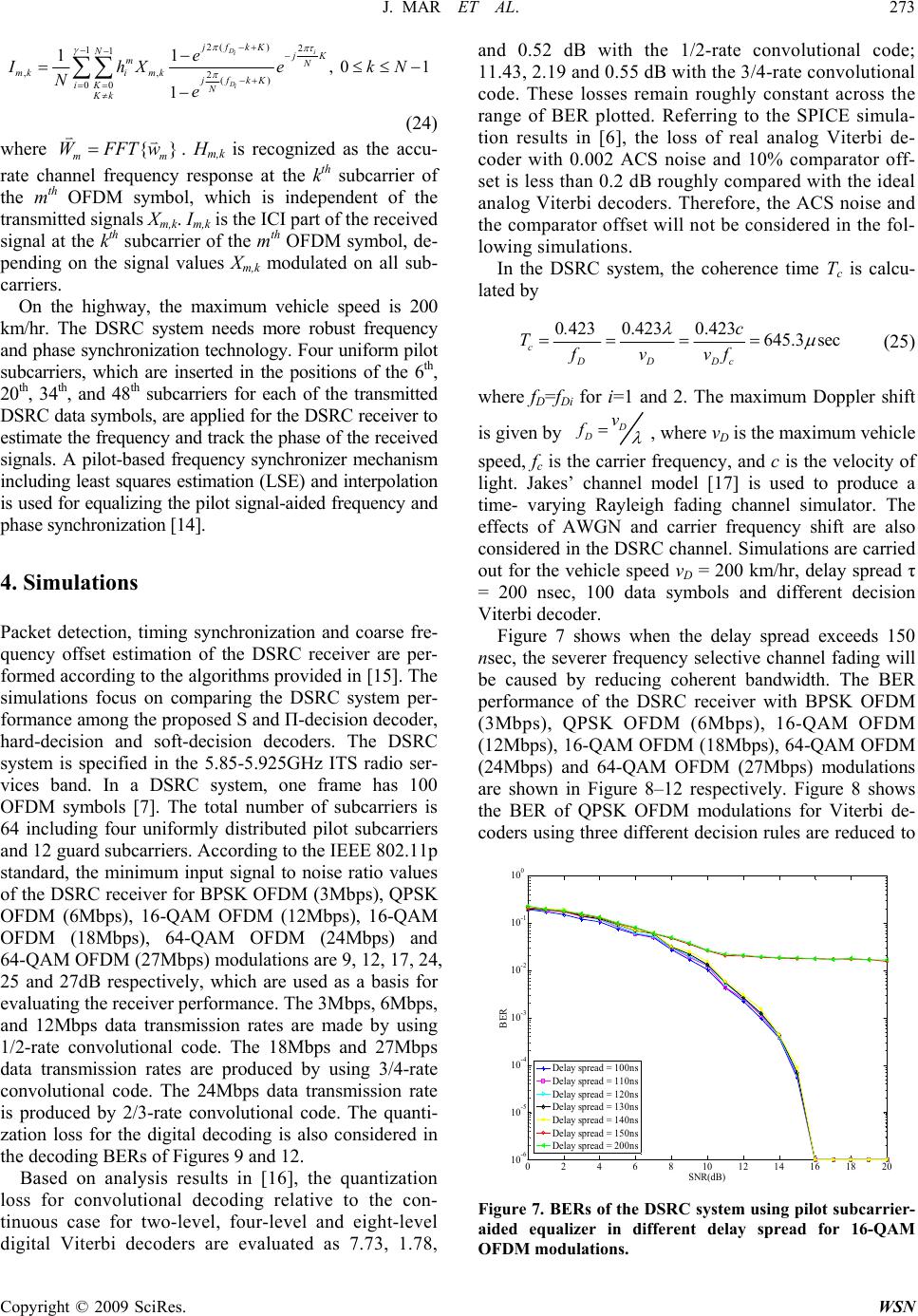 J. MAR ET AL.273 2() 2 11 ,, 2() 00 11 , 01kN 1 Di i Di jfkK NjK mN mkimkjfkK iK N Kk e IhXe Ne n ic ted signals Xm,k. Im,k is the ICI part of the received signal at the kth subcarrier of the m pending on the signal values Xm,k m carriers. On the highway, the maximum vehicle speed is 200 km/hr. The DSRC system needs mo and phase synchronization technology. Four uniform pilot subcarriers, which are inserted in the positions of the , 20th, 34th, and 48th subcarriers for each of the transmitted DSRC data symbols, are applied for the DSRC receiver to estimate the frequency and track the phase of the rece signals. A pilot-based frequency synchronizer mechanism including least squares estimation (LSE) and interpolation is used for equalizing the pilot signal-aided frequency and phase synchronization [14]. M OFDM (24Mbps) and 4-QAM OFDM (27Mbps) modulations are 9, 12, 17, 24, ctively, which are used as a basis for ver performance. The 3Mbps, 6Mbps, (24) where {} mm WFFTw . Hm,k is recognized as the accu- rate channel frequency respose at the kth subcarrier of the mth OFDM symbol, whh is independent of the transmit th OFDM symbol, de- odulated on all sub- re robust frequency 6th ived 4. Simulations Packet detection, timing synchronization and coarse fre- quency offset estimation of the DSRC receiver are per- formed according to the algorithms provided in [15]. The simulations focus on comparing the DSRC system per- formance among the proposed S and Π-decision decoder, hard-decision and soft-decision decoders. The DSRC system is specified in the 5.85-5.925GHz ITS radio ser- vices band. In a DSRC system, one frame has 100 OFDM symbols [7]. The total number of subcarriers is 64 including four uniformly distributed pilot subcarriers and 12 guard subcarriers. According to the IEEE 802.11p standard, the minimum input signal to noise ratio values of the DSRC receiver for BPSK OFDM (3Mbps), QPSK OFDM (6Mbps), 16-QAM OFDM (12Mbps), 16-QAM OFDM (18Mbps), 64-QA 6 25 and 27dB respe valuating the receie and 12Mbps data transmission rates are made by using 1/2-rate convolutional code. The 18Mbps and 27Mbps data transmission rates are produced by using 3/4-rate convolutional code. The 24Mbps data transmission rate is produced by 2/3-rate convolutional code. The quanti- zation loss for the digital decoding is also considered in the decoding BERs of Figures 9 and 12. Based on analysis results in [16], the quantization loss for convolutional decoding relative to the con- tinuous case for two-level, four-level and eight-level digital Viterbi decoders are evaluated as 7.73, 1.78, and 0.52 dB with the 1/2-rate convolutional code; 11.43, 2.19 and 0.55 dB with the 3/4-rate convolutional code. These losses remain roughly constant across the range of BER plotted. Referring to the SPICE simula- tion results in [6], the loss of real analog Viterbi de- coder with 0.002 ACS noise and 10% comparator off- set is less than 0.2 dB roughly compared with the ideal analog Viterbi decoders. Therefore, the ACS noise and the comparator offset will not be considered in the fol- lowing simulations. In the DSRC system, the coherence time Tc is calcu- lated by 0 4230.4230.423645.3 sec c DDDc . c Tfvvf (25) where fD=fDi for i=1 and 2. The maximum Doppler shift is given by D D v f , where vD is the maximum vehicle speed, fc is the carrier frequency, and c is the velocity of light. Jakes’ channel model [17] is used to produce a time- varying Rayleigh fading channel simulator. The effects of AWGN and carrier frequency shift are also considered in the DSRC channel. Simulations are carried out for the vehicle speed vD = 200 km/hr, delay spread τ = 200 nsec, 100 data symbols and different decision Viterbi decoder. Figure 7 shows when the delay spread exceeds 150 nsec, the severer frequency selective channel fading will be nce of the DSRC receiver with BPSK OFDM (3Mbps), QPSK OFDM (6Mbps), 16-QAM OFDM (12Mbps), 16-QAM OFDM (18Mbps), 64-QAM (24Mbps) and 64-QAM OFDM (27Mbps) mo are shown in Figure 8–12 respectively. Figure 8 shows g three diffe caused by reducing coherent bandwidth. The BER performa OFDM dulations the BER of QPSK OFDM modulations for Viterbi de- coders usinrent decision rules are reduced to 0246810 12 14 16 18 20 10 -6 10 -5 10 -4 10 -3 10 -2 10 -1 10 0 BER SNR(dB) Delay spread = 100ns Delay spread = 110ns Delay spread = 120ns Delay spread = 130ns Delay spread = 140ns Delay spread = 150ns Delay spread = 200ns Figure 7. BERs of the DSRC system using pilot subcarrier- aided equalizer in different delay spread for 16-QAM OFDM modulations. Copyright © 2009 SciRes. WSN  274 J. MAR ET AL. 02 4 6 810 12 10 -6 10 -4 10 -2 10 0 BER SNR(dB) hard-decision four-level soft-decision S and -decision Figure 8. Comparisons of BERs of the QPSK DSRC system less than 10-5 at the minimum signal-to-noise ratio (SNR), which meets the requirements specified in the IEEE 802.11p standard. When the quantization loss for the convolutional decoding is considered, the BER of 16-QAM OFDM DSRC system is shown in Figure 9, where using a hard- decision Viterbi decoder is higher than 10-5 at the minimum SNR (17dB) for the case of the 12Mbps data transmission rate. The 16-QAM OFDM DSRC system using the four-level and eight-level soft-decision and analog Viterbi decoders will be reduced to less than 10-5 at the minimum SNR (17dB), which meet the re- quirements specified in the IEEE802.11p standard. It is noted the S and Π-decision decoders results in a coding gain of 1.5 dB and 5.2dB compared to the eight-level using the hard-decision de- oder cannot be lower than 10-5, when the data trans- -ray Rayleigh fading channel envi- ro shown in Figure 12, where the quantization loss for the (6 Mbits/sec; 200km/h; code-rate is 1/2) in terms of the dif- ferent decision decoders. and four-level soft-decision decoders, respectively, when the quantization loss for the convolutional de- coding is considered. Figure 10 shows the BER of 16-QAM DSRC system c mission rate increases to 18Mbps. The hard-decision curve has a floor that is generated by the hard-decision loss under the two nment. The 16-QAM DSRC system using both the soft-decision decoder and the S and Π-decision decod- ers will reduce the BER to less than 10-5 at the mini- mum SNR (24dB), which meets the requirements specified in the IEEE802.11p standard. The S and Π-decision decoder has a 1.5dB coding gain compared with the four-level soft-decision decoder. Figure 11 shows the BER of 64-QAM DSRC system under the conditions of 18 Mbits/sec data rate and 200km/h vehicle speed cannot be lower than 10-5 for three different Viterbi decoders. All three BER curves have the floors that are caused by the high-order 64- QAM modulation DSRC system operated under the fast fading channel. The BER of 64-QAM DSRC system is 0510 15 20 25 10 -6 10 -5 10 -4 10 -3 10 -2 10 -1 10 0 BER SNR(dB) hard decision four- level so ft-decision eight-level soft-decision S and -decision Figure 9. Comparisons of BERs of the 16-QAM DSRC sys- tem (12 Mbits/sec; 200km/h; code-rate is 1/2) in terms of the different decision decoders with quantization loss. 05 1015 20 2530 10 -6 10 -4 10 -2 10 0 BER SNR(dB) hard-decision four-level soft-decision S a nd -decision Figure 10. Comparisons of BERs of the 16-QAM DSRC system (18 Mbits/sec; 200km/h; code-rate is 3/4) in terms of the different decision decoders. 05 10 152025 30 10-6 10-4 10-2 100 BER SNR(dB) hard-decision fou r-level soft -decisi on S and -decision Figure 11. Comparisons of BERs of the 64-QAM DSRC system (24 Mbits/sec; 200km/h; code-rate is 2/3) in terms of the different decision decoders. Copyright © 2009 SciRes. WSN  J. MAR ET AL. 275 Copyright © 2009 SciRes. WSN NSC 96-2219-E-155-005. 7. References [1] K. M. Lee, D. S. Han, and K. B. Kim, “Performance of the Viterbi decoder for DVB-T in Rayleigh fading chan- nels,” IEEE Trans. Consumer Electron., Vol. 44, pp. 994–1000, August 1998. [2] S. B. Wicker, “Error control systems for digital communi- cation and storage,” New Jersey, Prentice-Hall, Inc., 1995. [3] F. Tosato and P. Bisaglia, “Simplified soft-output de- mapper for binary interleaved COFDM with application to HIPERLAN/2,” in Proc. IEEE Int. Conf. Communica- tions, Vol. 2, pp. 664–668, April 2002. [4] E. Akay and E. Ayanoglu, “Low complexity decoding of bit-interleaved coded Modulation for M-ary QAM,” in Proc. IEEE Int. Conf. Communications, Vol. 2, pp. 901– 905, June 2004. 01020 3040 10 -6 10 -5 10 -4 10 -3 10 -2 10 -1 10 0 BER SNR(dB) har d decision four-l evel soft -deci si on eight-l evel soft-deci sion S and -decision Figure 12. Comparisons of BERs of the 64-QAM DSRC system (27 Mbits/sec; 120km/h; code-rate is 3/4) in terms of the different decision decoders with quantization loss. owed the 64-QAM DSRC system using three different decoders can be reduced to less than 10-5 at the minimum SNR (27dB), which meets the requirements specified in IEEE802.11p standard. The S and Π-decision decoder results in a coding gain of 2.5 dB, 5dB and 15 dB compared to the eight-level soft-decision, four-level soft-decision and hard-decision Viterbi decoders, respectively, when the quantization loss for the digital Viterbi decoding is considered. 5. Conclusions A new S and Π-decision rule is proposed for the analog demapper of the OFDM system. The DSRC system is chosen as an OFDM platform to compare the perform ance of the S and Π-decision decoder, which consists ain of the S and Π-decision decoder relative t convolutional decoding is considered and the vehicle speed reduces to vm = 120 km/hr. It sh - of an S and Π-decision demapper, analog deinterleaver and an analog Viterbi decoder, with hard-decision and soft- decision decoders. Simulation results show the coding og four-level and eight-level soft-decision decoders are evaluated as 5.4dB and 1.5 dB, respectively, with the 16-QAM DSRC system; and 5dB and 2.5 dB with the 64-QAM DSRC system when the quantization loss for the convolution decoding is considered. Each analog demapper output can be determined by looking-up S and Π table 2 log M times for M-ary QAM OFDM systems. Many other applications related to OFDM with the pro- posed S and Π-decision decoder are possible. 6. Acknowledgement he authors would like to acknowledge gratefully the search grants from National Science Council, Taiwan, ] K. He and G. Cauwenberghs, “Performance of analog idwest Symposium on Circuits ust 1999. een Roadside and Vehicle Sys- tem–5Ghz Band Dedicated Short Range Communications ccess Control (Mac) and Physical Layer ations, IEEE802.11p, December 2005. decoders,” IEEE main processing,” in peci- ett., Vol. 7, No. 9, pp. 446–448, Sep- Communications, New York: IEEE Press, 1974. [5 Viterbi decoding,” 42nd M and Systems, Vol. 1, Aug [6] K. He and G. Cauwenberghs, “Itergrated 64-state parallel analog Viterbi decoder,” ISCAS 2000, Vol. 4, May 2000. [7] Standard Specification for Telecommunications and Infor- mation Exchange Betw (DSRC) Medium A (PHY) Specific [8] S. Coleri, M. Ergen, and A. Bahai, “Channel estimation techniques based on pilot arrangement in OFDM sys- tems,” IEEE Trans. Broadcast., Vol. 48, pp. 223–229, September 2002. [9] J. Giarratano and G. Riley, Expert Systems, 2nd. Edition, PWS Publishing Company, 1994. [10] J. Heiskala and J. Terry, OFDM Wireless LANs: A Theo- retical and Practical Guide, Sams, 2001. [11] V. C. Gaudet, R. J. Gaudet, and P. G Gulak, “Programma- ble interleaver design for analog iterative Trans. Circuits Syst. II, Vol. 49, pp. 457–464, July 2002. [12] D. G. Manolakis, V. K. Ingle, and S. M. Kogon, “Statis- tical and adaptive signal processing,” McGraw-Hill, Edu- cation, 2000. [13] Y. Zhao and A. Huang, “A novel channel estimation method for OFDM mobile communication systems based on pilot signals and transform-do Proc. IEEE VTC, Vol. 3, pp. 2089–2093, May 1997. [14] J. Rinnie and M. Renfors, “Pilot spacing in orthogonal frequency division multiplexing systems on practical channels,” IEEE Trans. Consumer Electron., Vol. 42, No. 4, pp. 959–962, November 1996. [15] IEEE 802.11a, IEEE standard for Wireless LAN Medium Access Control (MAC) and Physical Layer (PHY) s fications, 1999. [16] M. R. G. Butler and A. R. Nix, “Quantization loss for convolutional decoding in Rayleigh-fading channels,” IEEE Commun. L tember 2003. [17] W. C. Jakes, Microwave Mobile T re |