Journal of Materials Science and Chemical Engineering
Vol.06 No.04(2018), Article ID:83662,10 pages
10.4236/msce.2018.64007
Analysis of Strain Clamp Failure on 500 kV Transmission Line
Mingcheng Sun1*, Che Tan2, Chaoqun Zhang1, Chao Yang1, Hongqiang Li1
1State Grid Liaoning Electric Power Research Institute, Shenyang, China
2State Grid Shenyang Electric Power Supply Company, Shenyang, China


Received: December 21, 2017; Accepted: April 5, 2018; Published: April 12, 2018
ABSTRACT
In this work, the main reasons for the breakage of 500 kV transmission line are studied. Under low temperature condition, the coverage of the ice results in the disconnection between the aluminum tube and the steel anchor of strain clamp. Using macroscopic analysis, structure stress analysis, force analysis and mechanical property test, the fractured strain clamps are investigated. The crimping of the aluminum tube on the polished rod not on the grooves of the steel anchor leads to the damage of the strain clamps, which is defined as improper crimping. When improper crimping emerges, there will be only friction force between the aluminum tube and the steel anchor without shear force, and the tension of the conductor will be mainly supported by the steel strands which should be supported by both the aluminum tube and steel stands. Therefore, the breaking force of the strain clamp will greatly decrease. The failure analysis helps to promote the proper hydraulic crimping process and the safe operation of the transmission line.
Keywords:
Transmission Line, Strain Clamp, Hydraulic Crimping Process

1. Introduction
Aluminum cable steel reinforced (ACSR) conductors that are the key component of the high-voltage transmission line are widely used in electric transmission systems around the world, especially in China [1]. As another important electric fitting of the high-voltage transmission line, strain clamp should meet the transmission function of mechanical and electrical loading in ACSR conductors across towers. Strain clamp is composed of aluminum tube and steel anchor and has large grip strength and high reliability which is widely used in 500 kV transmission lines and other large cross-sectional conductors and plays a crucial role in the safety and the stability of high-voltage transmission lines.
ACSR conductors and strain clamps are usually subject to damage caused by wild environments, such as the coverage of the ice under low temperature condition. However, owing to the shortage of construction period and the lack of effective testing methods after crimping, the crimping quality of the strain clamp can not be effectively guaranteed [2]. The failure of the strain clamp has also occurred due to fatigue, material defects and hydraulic crimping process [3].
The primary aim of this study is to investigate the main reasons for the breakage of 500 kV transmission line. The dissection of the aluminum tube was carried out and the position of the steel anchor in the aluminum tube was analyzed. Mechanical property test of strain clamps for crimping into different locations on the aluminum tube were carried out. The work explored the key factors that affect the crimping quality and breaking force of strain clamp. The rated tensile strength of the aluminum strands and the steel strands to conductor was calculated through ACSR parameters. The study will contribute to the further enhancement of the safety and the improvement of the performance for high-voltage transmission lines.
2. Experimental
2.1. Overview of the Accident
The length of the 500 kV transmission line was 90.13 km, designed with double circuit on the same tower, 4 division JL/G1A-630/45-45/7 aluminum conductor steel reinforced (ACSR) and 2.5 safety factor. The ice thickness tolerance of transmission line was set as 10 mm. The model of the strain clamp was NY-630/45. The project preliminary design review was completed in October 2008, and the construction drawing design began in February 2009. On June 30, 2012, the 500 kV transmission line started running.
On November 7, 2015, the rare ice disaster weather in northeastern China caused the disconnection of 500 kV transmission lines. The fractured strain clamps and conductors of 500 kV transmission line are shown in Figure 1. The strain clamp for large side middle phase (A phase) on No. 16 strain tower of 500 kV transmission lines (double circuit in the direction of the right loop) was disconnected, with all the 4 root wires disconnected and landed. The strain clamp for small side middle phase (A phase) on the same tower also disconnected, with 3 root wires disconnected and 1 root wire not landed. The failure of strain clamps on No. 16 tower led to the breakage and landing of 3 root wires on the adjacent No. 14 and No. 15 tower middle phase (A phase). But all the towers were intact.
The initial failure point of the ice disaster was the No. 16 strain tower. 7 strain clamps on the No. 16 strain tower were damaged and out of work. The steel strands broke at the exit of the strain clamp, and the steel anchors were pulled out of the aluminum tube which brought about the injury of aluminum tube.
 (a)
(a)
 (b)
(b)
Figure 1. The fractured strain clamps and conductors of 500 kV transmission line (a) the fractured conductors (b) the steel anchors out of the strain clamps.
In the ice disaster, large number of the strain clamps were severely damaged and lots of fractures emerged. The fracture of strain clamps had been a common issue in the ice disaster.
2.2. Theoretical Calculation of Conductor Force
The model of conductor on 500 kV transmission lines was JL/G1A-630/45-45/7, which consisted of 45 hard aluminum stranded wires and 7 common strength galvanized steel wires. The nominal cross-sectional area of the hard aluminum stranded wires was 630 mm2, while the nominal cross-sectional area of steel strands was 43.6 mm2.
Rated breaking force of ACSR = Minimum tensile strength before aluminum wire stranded × nominal cross-sectional area of the hard aluminum stranded wires+ Stress at 1% elongation of galvanized steel wire × nominal cross-sectional area of steel strands = 160 × 630 + 1140 × 43.6 = 150,450.
The proportion of aluminum strands to the total rated breaking force of the ACSR is
 .
.
The proportion of the steel strands to the total breaking force of the ACSR is.

According to GB/T 3428-2002 “galvanized steel wires for overhead stranded conductors” [4] and GB/T 1179-2008 “round wire concentric lay overhead stranded conductors” [5]. ACSR parameters were calculated and the results were shown in Table 1.
We tested the dominating mechanical properties of 7 fractured steels, as shown in Table 2. The tensile strength and elongation after fracture of the 7 steels met the standard requirements of GB/T 3428-2002 “Zinc-coated steel wires for stranded conductors”. All samples possessed the tensile strengh value higher than 1490 MPa and the elongation ratio after fracture above 4.6%, which exceeded the national standard.

Table 1. JL/G
Table 2. The tensile strength (in MPa) and elongation after fracture (in %) of fractured steels.
2.3. Analysis of Fractured Steel Strands of the Strain Clamp
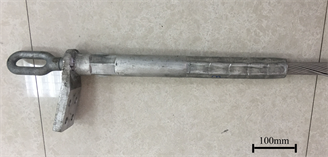
One of the landed strain clamp on site was shown in Figure 2(a). One of the 7 fractured strain clamps was selected for dissection and verification, since the location and performance of the damaged sections were basically the same. The dimple plastic fracture morphology of the internal core steels of the strain clamp was shown in Figure 2(b).
The rated breaking force of ACSR was defined as the sum of the breaking force of aluminum strands and the tension of the steel strand at the same time. The breaking force of the core steel referred to the stress at 1% elongation by the 250 mm gauge distance. The total rated breaking force ratio of aluminum strands to ACSR was 67% and that of steel strands to ACSR was 33%.
The opinion that the outer aluminum strands only contributed to the conductor but not to the force was inexact. The rated tensile strength of the
 (a)
(a)  (b)
(b)
Figure 2. One of the landed strain clamp of 500 kV transmission line (a) fractured strain clamp on site (b) the fracture morphology of the core steels.
aluminum strand to conductor was 67% and the rated tensile force of the steel strands to conductor was 33% by calculation. Therefore, special attention should be payed to the influence of tensile strength on the aluminum strands [6].
The steel strands were designed to afford about 33% rated tensile strength of JL/G1A-630/45-45/7 conductor. Under normal operating conditions, the rated tensile strength of conductor tension should be below 25%, so the conductor tension only afforded by the steel strands was still within the safe range.
According to the results of field ice measurement, the actual ice thickness of the ice disaster conductor was 38.7 mm [7]. According to the calculation results, the upper limit of theoretical ice thickness tolerance for the conductor should be 42 mm. When the ice thickness was larger than this value, the tension of the conductor will exceed the conductor tensile strength and the conductor may be broken [8]. The conductor tension value was 131,500 N for the 486 m span which was lower than the conductor breaking force 150,450 N. This was consistent with the conductors which were intact in the middle of the span.
3. Result and Discussion
3.1. Structural Analysis of Strain Clamp
Figure 3 shows the structure of the strain clamp. The strain clamp consists of aluminum tube and steel anchor. The steel tube in front of the steel anchor holds the steel strands. The aluminum tube at one end holds the ACSR, and the other end holds the steel anchor. The aluminum tube acts as a bridge: one end connected to the aluminum strands and the other connected to the steel anchor [9].
The aluminum stranded wires of conductor near the crimping area of steel anchor have been stripped. The force of aluminum strands has been replaced by aluminum tube, indicating that they afford 67% of rated breaking force on the conductor. This part of the force can be divided into the friction force and shear force on the hydraulic connection between the aluminum tube and the steel anchor. The friction force on the aluminum tube and the steel anchor is proportional to the crimping length of the aluminum tube on the steel anchor, while the shear force on the aluminum tube and the steel anchor is proportional to the number of grooves and the length of the grooves [10].
 (a)
(a)  (b)
(b)
Figure 3. Structure of strain clamp.
3.2. Failure Analysis of Strain Clamp
The aluminum tube broken on site is shown in Figure 4. The steel anchor pulled out from the aluminum tube has a smooth surface without obvious trace of slippage. Judged from the damage of strain clamps, the crimping position may be the main reason for the breakage of strain clamp. To further confirm this, the dissection of the aluminum tube is carried out and the position of the steel anchor in the aluminum tube is analyzed. The crimping region of aluminum tube is smooth and there is no crimping mark on steel anchor grooves, which indicates that the aluminum tube is not crimped on the grooves of steel anchor.
In order to verify the tension difference of the different crimping positions of the steel anchor on the aluminum tube, the mechanical properties are tested. Strain clamp hydraulic crimping can be divided into proper process and improper process.
The crimping of aluminum tube on the grooves of the steel anchor is shown in Figure 5(a). The two aluminum tubes at both ends of the conductor are completely crimped on the grooves of the steel anchor. After the test of mechanical properties, the conductor breaks at the exit of the strain clamp, and the position of the aluminum tube and the steel anchor does not change.
The hydraulic crimping of aluminum tube on the steel anchor polished rod is improper. As shown in Figure 5(b), the two aluminum tubes at both ends of the conductor are crimped on the polished rod of the steel anchor. After the mechanical test, the steel anchor is pulled out 50 mm of the aluminum tube leaving aluminum scratches on the steel anchor. The mechanical testing machine will automatically unload and stop test after reaching the peak value. If the tension load is constant, the steel anchor will be completely removed from the aluminum tube. This is consistent with the pull-out of steel anchor from the aluminum tube under ice conditions on site.
The rated tensile strength of conductor Tp is 150,450 N, while the strain clamp calculated rated tensile strength 95% 95%Tp is 135,781 N.
As shown in Table 3, the tensile strength is 152,770 N when the aluminum tube is crimped on the grooves of steel anchor properly. This value is obviously higher than the standard required value of strain clamp 135,781 N. And the tensile strength is 119,010 N when the aluminum tube is crimped on the polished

Figure 4. The dissection of the strain clamp.
 (a)
(a)  (b)
(b)
Figure 5. (a) The aluminum tube crimping into different locations of the steel anchor (a) on the grooves (b) on the polished rod.
Table 3. Tensile strength of aluminum tube crimped on grooves and polished rod of steel anchor.
rod of steel anchor improperly. This value is lower than the boundary value and only reach 88% of the required value, so the safety coefficient of conductor is not able to meet the requirements. Under extreme conditions such as the thick ice conditions, the ice thickness tolerance of the conductor will also decrease.
When the aluminum tube was crimped on the grooves of steel anchor, the ACSR broke at the exit of the strain clamp. The facture surface morphologies of the fractured aluminum strands after mechanical test were shown in Figure 6. The fracture surface morphologies of the aluminum strands were plastic necking fracture. When the aluminum tube was crimped on the polished rod of steel
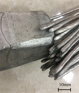
Figure 6. The facture surface morphologies of the fractured aluminum strands after mechanical test.
anchor, the steel anchor would slip at the peak strength and the mechanical test would stop then, the ACSR and strain clamp would not break and there were no surface morphologies.
Since the aluminum tube is crimped on the polished rod not on the grooves of the steel anchor, there is only friction force between the aluminum tube and the steel anchor without shear force. The breaking force of the strain clamp is greatly decreased. Therefore, the damage strain clamp arose.
67% of rated ACSR breaking force can be divided into the friction force and shear force on the hydraulic connection between the aluminum tube and the steel anchor. The shear force is more reliable than friction force in the mechanical test. The effect of friction force is less than the effect of shear force in the strain clamp mechanical test. Therefore, the tensile strength of aluminum tube crimped on polished rod is less than on grooves of steel anchor.
According to the measurements of field ice, the actual ice thickness on the conductor in the ice disaster was 38.7 mm. Because of the improper crimping, the tension of the conductor is mainly supported by the steel strands which should be supported by both the aluminum tube and core steel. Under larger loads, such as thick ice, the steel strands will break and the steel anchor will slip, while the conductor will fall down [11]. The conductor tension value of the 486 m representing span is 131,500 N, which is lower than the conductor breaking force (150,450 N). So the conductor doesn’t break. For the improper crimping, the tension value of strain clamp (131,500 N) is higher than breaking force (119,010 N). So the strain clamp breaks in the strain clamp exit, which is consistent with the actual situation.
4. Conclusion
The main reasons for the breakage of 500 kV transmission line is the disconnection between the aluminum tube and the steel anchor of strain clamp due to the improper crimping of the aluminum tube with thick ice. When the aluminum tube is crimped on the grooves of steel anchor, which is proper crimping process, the tensile strength will meet the standards for strain clamp in DL/T 5285-2013 “hydraulic crimping process specification for overhead conductor and ground wire of transmission and transformation project construction”. And when the aluminum tube is crimped on polished rod of the steel anchor, which is improper crimping process, the tensile strength will not meet the standard requirements of strain clamp. The aluminum tube of the fractured strain clamp is crimped on the polished rod of the steel anchor, which indicates the hydraulic crimping process does not meet the requirements. When improper crimping emerges, there will be only friction force between the aluminum tube and the steel anchor without shear force, and the tension of the conductor will be mainly supported by the steel strands which should be supported by both the aluminum tube and steel stands. The breaking force of the strain clamp will be greatly decreased. Therefore, larger loads, such as thick ice, will lead to the breakage of the steel strands, the slip of steel anchors, and the drop of conductors. More attention should be paid to the hydraulic process of strain clamp in the future. The hydraulic crimping process should be strictly carried out according to the standards and regulations so as to avoid the improper crimping.
Cite this paper
Sun, M.C., Tan, C., Zhang, C.Q., Yang, C. and Li, H.Q. (2018) Analysis of Strain Clamp Failure on 500 kV Transmission Line. Journal of Materials Science and Chemical Engineering, 6, 47-56. https://doi.org/10.4236/msce.2018.64007
References
- 1. Ma, X.Ch., Gao, L., Zhang, J.X. and Zhang, L.Ch. (2017) Fretting Wear Behaviors of Aluminum Cable Steel Reinforced (ACSR) Conductors in High-Voltage Transmission Line. Metals, 7, 373. https://doi.org/10.3390/met7090373
- 2. Aggarwal, R.K., Johns, A.T., Jayasinghe, J.A.S.B. and Su, W. (2000) An Overview of the Condition Monitoring of Overhead Lines. Electric Power Systems Research, 53, 15-22. https://doi.org/10.1016/S0378-7796(99)00037-1
- 3. Liu, C., Xiong, L., Chen, H.D. and Li, X. (2010) Fracture Analysis of Steel Anchor for Tension Line Clamp of 500kV Transmission Line. Shanghai Electric Power, 4, 264-266.
- 4. GB/T 3428-2002. Galvanized Steel Wires for Overhead Stranded Conductors.
- 5. GB/T 1179-2008. Round Wire Concentric Lay Overhead Stranded Conductors.
- 6. Huang, N., Zhang, Y., Pan, L.B. and Yang, L.Z. (2012) Analysis of Strain Clamp Fracture in 500 kV Transmission Line. Guangxi Electric Power, 35, 63-65.
- 7. Zeng, X.J., Luo, X.L., Lu, J.Z., Xiong, T.T. and Pan, H. (2012) A Novel Thickness Detection Method of Ice Covering on Overhead Transmission Line. Energy Procedia, 14, 1349-1354. https://doi.org/10.1016/j.egypro.2011.12.1100
- 8. Wang, Z.J. (2017) Recent Progress on Ultrasonic De-Icing Technique Used for Wind Power Generation, High-Voltage Transmission Line and Aircraft. Energy and Buildings, 140, 42-49. https://doi.org/10.1016/j.enbuild.2017.01.072
- 9. Chen, G.H., Wang, X., Wang, J.Q., Liu, J.J., Zhang, T. and Tang, W.M. (2012) Damage Investigation of the Aged Aluminum Cable Steel Reinforced (ACSR) Conductors in a High-Voltage Transmission Line. Engineering Failure Analysis, 19, 13-21. https://doi.org/10.1016/j.engfailanal.2011.09.002
- 10. Hu, J.R., Liu, C., Ouyang, K.J., Xie, Y., Mou, S.Z. and Chen, Y. (2012) Analysis on Cracking Failure of Strain Clamp on 500 kV DC Transmission Line. Electric Power Construction, 7, 82-85.
- 11. Li, X.H., Wu, H.L., Ding, H. and Zhu, C.L. (2014) Simulation and Failure Analysis of Strain Clamp Failed Caused by Deterioration of Contact Resistance. Recent Advances in Structural Integrity Analysis—Proceedings of the International Congress (APCF/SIF-2014), 212-217.