World Journal of Engineering and Technology
Vol.05 No.04(2017), Article ID:83569,7 pages
10.4236/wjet.2017.54B016
Comparison of the Radar Receiver Anti-Jamming Circuits Performance
Shuhua Li, Baopeng Li
Qingdao Branch of Naval Aeronautical Engineering Institute, Qingdao, China


Received: July 18, 2017; Accepted: October 9, 2017; Published: October 12, 2017
ABSTRACT
This paper researches on some key technologies of anti-jamming of an airborne radar receiver, the automatic testing of AGC, IAGC and multi-filtering under one million noisy pulses by the computer simulation system. The system tests the width of the jamming pulse whose width is 100% bigger, 60% bigger and 100% smaller than the Radar signal’s respectively and show the SNR curve.
Keywords:
Multi-Filtering, Anti-Jamming Circuits, SNR Curve

1. Introduction
The use of radar in the War was quickly followed by the development of anti-radar equipments in order to reduce their performance. Radar jamming and anti-jamming are two opposing techniques. The application of a new radar technology will lead to a new jamming technology, and new interference will inevitably lead to new radar anti-jamming measures. This cycle has led to the development of radar jamming and anti-jamming techniques [1].
Special focus is given to the radar receiver in the paper. Investigations of the effects of anti-jamming circuits led to the establishment of design practices which resulted in appreciable reduction of the general vulnerability of equipments; details are given of these practices. The experiments deal with wide & narrow, adjacent noise automatic gain control, IAGC, multilevel filter anti-jamming measures against 1 million pulses per second signal interference conditions. Comparison of these measures is performed respectively before and after the pulse interference signal was added, when the jamming signal’s width is more than 100%/60% greater than 100% and less than the pulse width of the radar signal and the condition of three groups of quantitative analysis data are given; Then the quantitative analysis of the receiver filter bandwidth of noise energy before and after filtering than changes in 0.6 - 0.8, which provides the quantitative basis for the receiver filter bandwidth selection.
2. Experimental System Design and Result Analysis
2.1. System Overall Design
In view of the different systems, different uses of the internal processing mechanism of radar vary greatly [2]. The research focuses on the research of phased array radar system from two aspects of theory and experiment, analysis and Simulation of the various methods of anti jamming effect. The experimental system is centered on signals. The interference signal generating module mainly produces all kinds of jamming signal simulation module is responsible for all kinds of interference signals may be mixed with the complex electromagnetic environment signals such as the receiver input signal; analog signal processing module is divided into functional modules of small analog receiver processing function, signal processing, intermediate code can be embedded to compare the anti-jamming, integration and control simulation experiment; the main control module is responsible for the scheduling and radar system; output statistics module is responsible for the output of the statistical and graphical display.
2.2. Principle and Modeling of Radar Signal Processing
Pulse Doppler processing mainly refers to the processing of high repetition frequency signals, including filtering, Doppler filtering, detection, 2D CFAR [3].
Radar transmit signals can be described as
(1)
Among them, the carrier frequency, is the peak power of the transmitter, the transmit loss is , is the transmit antenna pattern; the complex modulation function is a coherent pulse train consisting of a rectangular pulse with a width .
In consideration of the digital signal processing, most of the modern radar so described below domain processing method of matching filter, the basic principle is: FFT of the input signal, multiplied by the frequency response function, digital filter, the signal sequence of IFFT compressed output [4]. Similarly, the frequency response function of the matched filter is the complex conjugate of the FFT transform of the input signal in a radar period, not the whole input signal. Specific steps are as follows:
1) Design matched function for transmitting signals
(2)
where b represent for linear frequency modulation, the slope sampling rate is , and the signal number is (pulse width ), is the coefficient of the matched filtering function.
2) Windowing
, (3)
where is the window function.
3) Zero padding FFT processing
(4)
4) The radar target echo signal is transformed by Fu Liye transform
, , (5)
5) Matched filter output:
(6)
2.3. Experiment of Anti-Interference Circuit for Receiver
Anti-interference measures mainly around the part of the receiver circuit time constant control, gain control, adjustment of the threshold, with the auxiliary channel and signal accumulation, and gain control circuit with constant control often used in combination [5].
Inspired by the analysis of the reference [5], anti-jamming circuit in radar receiver, taking as the main object, wide & narrow, adjacent noise automatic gain control, IAGC, multilevel filter anti-jamming measures in 1 million pulses per second signal interference conditions, were measured respectively before and after the pulse interference signal anti-interference circuits are added. The SNR changes when the noisy signals’ width is 100% greater than 60% is greater than 100% and less than the pulse width of the radar signal under the condition of three groups of quantitative analysis data is given; then the quantitative analysis of the receiver filter bandwidth in 0.6 - 0.8 between the changes before and after filtering the noise energy ratio, which provides the quantitative basis for the receiver filter bandwidth choose.
In the experiment, firstly the jamming signal generation module generates 1 million pulses per second interference signal when the interference signals’ width is 100% greater than 60% is greater than 100% and less than the pulse width of the radar signal, the reference signal frequency is 100 MHz, pulse width is 1, the sampling rate is 3 times of the signal frequency.
The screenshot of the interference signal is shown in Figures 1-3, where the length of each frame is 0.001 ms, a total of 0.1 ms.
Through the calculation of before and after the addition of wide & narrow, the adjacent noise automatic gain control, IAGC, multilevel filter circuit signal to interference ratio (the target echo signal is 100 kilometers away), get the SNR curve as shown in Figure 4, which did not join the anti interference circuit SNR curve for the red curve, and the green curve to join the anti interference circuit after the SNR curve can be seen:
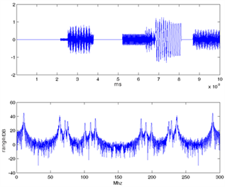
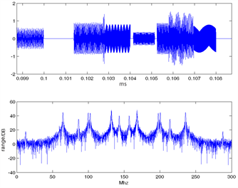
Figure 1. The pulse width of interference signal is 100% larger than that of radar signal pulse width.


Figure 2. The pulse width of interference signal is 60% larger than that of radar signal pulse width.
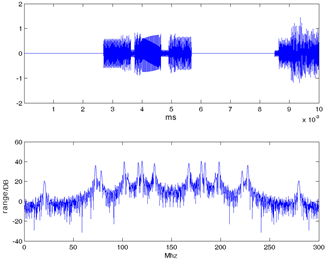
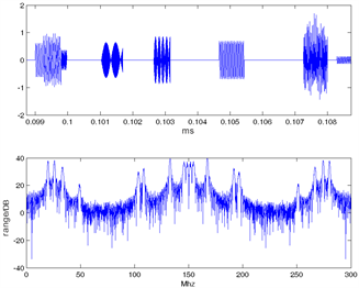
Figure 3. The pulse width of interference signal 100% is less than the jamming signal of radar pulse width.
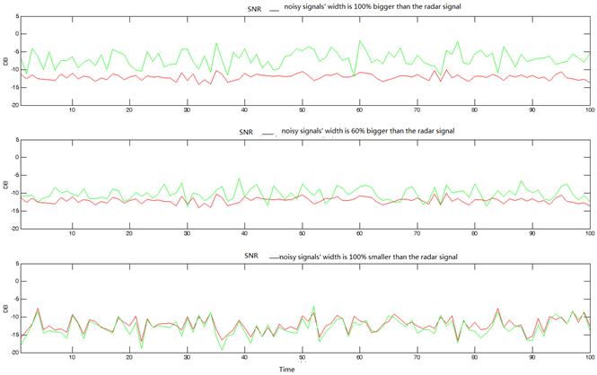
Figure 4. The change curve of the signal to dry ratio before and after the anti interference circuit is added.
1) when the initial interference free, the signals’ ratio is 0.5 - 2;
2) when the interference is weak, the improvement effect is better;
3) interference pulse width is greater than the pulse width of the signal, improve the 5 - 7 dB, the overall effect is best; more than 60% of the width of the pulse width of the signal interference, improve 2 - 4 DB in average, the pulse width is smaller than the middle; interference signal pulse width, improve 0 - 1 DB in average. Experiments show that the receiver anti-jamming circuit is designed for wide pulse interference.
In view of the optimal theoretical value receiver filter design (for Gauss type pulse signal and square wave type) for the =0.72, we make changes between 0.6 - 0.8 in the test, and the filter widening value changes in the 0.1 - 0.5 MHz, other parameters as above, get the change of noise into the receiver. Figure 5 shows the signals before and after the filter processing.
3. Conclusions
At present, although the radar receiver technology is relatively mature and has developed many anti-jamming circuit, the fierce combat conditions produce electromagnetic radiation signal types, full spectrum, high density, mutual influence will inevitably invade to the electronic equipment and strong interference, the receiver as the “front-line troops” against these signals in the complicated electromagnetic environment still need to do a lot of research work.

Figure 5. Noise signal before and after filtering.
Firstly, the signal density in future battlefield environment is expected up to 1.5 million pulses per second, the equivalent of 1800 sources of electromagnetic radiation and radiation combined [1], bear the brunt of this kind of high strength and high density of electromagnetic environment of radar receiver. If the residual interference is large enough after antenna interference, the saturation of receiver processing system will be caused, and the receiver saturation will lead to the loss of target information and the receiver will be burned. Therefore, it is necessary to develop the corresponding gain control and anti saturation circuit according to the use of radar. At present, the wide limited narrow circuit technology is mainly used to resist sweep frequency interference and wide pulse interference. For other types of interference and complex electromagnetic environment, the problem of receiving high intensity and high density signals is still not well solved.
Secondly, combination of various interference receiver circuit are worthy of further study. Our simulation experimental results show that, in addition to 1 million pulses per second interference, the wide-narrow limit circuit, adjacent noise automatic gain control, fast time constant and the double threshold anti-jamming circuit, can put on the radar the cross-sectional area of the 5m2 target detection probability is increased by 20%. However, the experience of using the actual device to show that the complex circuit structure and complex function combination can easily lead to the failure rate of the equipment to improve equipment reliability, resulting in the decline, the applicable scope and function of simple circuit and reduce equipment. Therefore, it is necessary to do a lot of experiments on how to set up a reasonable anti-interference circuit combination for the signal reception in complex electromagnetic environment.
Thirdly, in some cases, some of the existing instantaneous automatic gain control makes the signal pulse distortion, because it will make the amplifier bias back off state, even if only in peak signal pulse when the amplifier is in the linear region. Similar problems exist in many anti-jamming measures, that is to say, some anti-jamming circuit may optimize the signal detection under the condition of interference, but in some cases may be counterproductive, so in the development of the anti interference circuit at the same time also need to consider how to improve the robustness of anti-jamming circuit.
Fourthly, electromagnetic pulse bombs and other new weapons has brought forward new challenges to the survival of the radar receiver, how to take effective technology and tactics to prevent these new electromagnetic weapons attack known as one of the most important problems, which puts forward higher requirements on the circuit design of receiver protection.
At last, to provide some enlightenment on the existing double threshold detection and sequential detection method for setting the threshold in the complex electromagnetic environment, how to target differences between signal and disturbance to the traditional threshold calculation method to improve the detection probability, also look forward to the emergence of new ideas and methods.
Cite this paper
Li, S.H. and Li, B.P. (2017) Comparison of the Radar Receiver Anti-Jamming Circuits Performance. World Journal of Engineering and Technology, 5, 152-158. https://doi.org/10.4236/wjet.2017.54B016
References
- 1. Han X.D., Sun Q.Y., Shu, T., Tang, B. and Yu, W.X. (2017) Research Assessment. Anti Interference Test of Airborne Active Phased Array Radar. Modern Radar, 39, 91-96.
- 2. Yi, W. (2006) Radar Receiver Technology. Electronic Publishing House, Beijing.
- 3. Kang, C.G. (2017) Study on the Design Requirement of Ground Based Radar Receiver Using PD System. Modern Radar, 39, 83-86.
- 4. Song, X.X. (2016) Filter Circuit Design Based on Marine Navigation Radar Receiver. Electronic and Science University Press, Xi’an.
- 5. Zhang, J.T., Sun, H.H. and Duan, R.J. (2015) Review of the Research on Anti-Jamming Technology of Radar Receiver. Journal of Sichuan University of Arts and Science, 25, 36-40.