Open Access Library Journal
Vol.05 No.03(2018), Article ID:83371,14 pages
10.4236/oalib.1104446
Electrogravimetric Determination of Copper Using a Constructed Compact Electrolytic Cell
Dallatu E. Musa1,2, Rufus Sha’Ato1, Ishaq S. Eneji1, Adams U. Itodo1*
1Department of Chemistry, Federal University of Agriculture, Makurdi, Nigeria
2Department of Science Laboratory Technology, Federal Polytechnic, Nasarawa, Naarawa State, Nigeria
![]()
Copyright © 2018 by authors and Open Access Library Inc.
This work is licensed under the Creative Commons Attribution International License (CC BY 4.0).
http://creativecommons.org/licenses/by/4.0/


Received: February 26, 2018; Accepted: March 25, 2018; Published: March 28, 2018
ABSTRACT
Conventional electrolytic cells are usually cumbersome and simulated with fragile open ended glass wares such as beakers, tubes, troughs or tanks which are prone to interference and contamination. Electrolytic cell was designed by allotting dimensions for its length: 12.0 cm, breadth: 6.0 cm and height: 8.0 cm to the cell; its casing for 9.0 V power source was allotted 2.5 cm length, 2.5 cm breadth and 2.5 cm height; bores for dispensing and draining out spent (used) electrolyte and those for fixing electrodes were allotted 1.2 cm diameter; it was also designed to have an innovated switch and electrodes storage facility (compartment) of 7.0 cm length, 2.5 cm breadth and 2.5 cm height with ammeter separately fixed at the left edge of the cell’s electrolytes compartment. Perspex was used to construct a compact, durable and portable unit of electrolytic cell. Capacity of the cell was determined to be 500 cm3. Compactability tests show that the designed and constructed electrolytic cell is a compact unit. Conventional and the compact (constructed) electrolytic cells were separately used to perform electrogravimetry (electrolysis) 25.0 cm3 aliquot at 0.2 A for 10, 20, 30, 40, 50 and 60 mins. Relationship between mass (g) of electroplated Cu and time (10 to 60 mins) taken to electrolyze Cu in 25 cm3 aliquot was determined where conventional electrolytic cell electroplated 0.02 g to 0.22 g of Cu, compact electrolytic cell electroplated 0.03 g to 0.23 g of Cu and theoretically calculated mass of electroplated Cu in 25 cm3 aliquot was 0.04 g to 0.24 g respectively. Statistical comparison of the two set of systems at 95.0% percent confidence level indicated a significant difference in their performances. However at 99.0% - 99.9% confidence level the comparison showed that there is no significant difference in their performances. The results of this study buttress that Perspex is a good material for constructing compact, durable and portable electrolytic cells. It also showed that the constructed electrolytic cell is highly a sensitive tool as revealed by its ability to electroplate higher mass of electroplated copper than the conventional cell; that mass of electroplated copper and time of electrolysis have a positive correlation and statistical analysis revealed that the two sets of methods do not agree significantly with each other at 95.00% confidence level but they agree significantly with each other beyond this.
Subject Areas:
Electrochemistry
Keywords:
Electrochemistry, Electrolytic Cells, Design, Construction, Electrogravimetry Electrolysis

1. Introduction
The paradigm shift in the trend of chemistry from classical methods of analysis to instrumental methods has to do with system development and in the field of electrochemical analysis such system development will be incomplete without innovations in the area of voltaic and electrolytic cells.
According to [1] electrochemistry is a branch of chemistry that is concerned with the interaction of electrical and chemical effects. A large part of this field deals with the study of chemical changes caused by the passage of an electrical current and the production of electrical energy by chemical reaction. Electrochemical analysis refers to the use of electrical conductive probes or electrodes which are usually linked to electronic devices that measure the electrical parameters of the reactant in solution. [2] [3] and [4] categorized chemical analysis into classical or wet analysis and instrumental analysis. The first instrumental analysis was flame emissive spectrometry developed by Robert Bunsen and Gustav Kirchhoff who discovered rubidium (Rb) and caesium (Cs) in 1860 [3] .
Measurement according to [5] is the act or process of finding size, quantity, amount or degree of a parameter or something. Results of typical quantitative analyses are normally computed from two types of measurements: (1) mass or volume of sample to be analyzed and (2) measurement of some quantity that is proportional to the amount of analyte in a sample. Type (2) measurement normally completes the analysis [6] . Analytical methods are classified according to the nature of Type (2) measurement as gravimetric or electro gravimetric methods; volumetric (titrimetric) methods; spectroscopic methods and electro analytical methods. Some methods of Type (2) measurement such as the electrogravimetric, spectroscopic and electroanalytical methods are used to carry out investigation on chemical species in solution. Specific examples of such methods are electrolysis, coulometry, potentiometry, conductivity and voltammeter [6] .
Electrolysis and/or voltaic processes are the basis or the fundamental principles of three basic electro-analytical methods: electrogravimetry, potentiostatic coulometry and amperostatic coulometry or coulometric titration. The understanding of voltaic or galvanic cell and electrolytic cell is the knowledge of such electro-analytical techniques [6] .
In this study, a compact, durable and portable electrolytic cell was designed, constructed and used for electrogravimetric determination of copper to study the relationship between mass of electroplated copper and time of electrolysis compared with the use of conventional electrolytic cell which is usually simulated with opened fragile glass wares (in which electrolytes are prone to interference and contamination) whose assemblage is so cumbersome such that one person cannot lift it up. Statistical test of significant difference between the two methods was done. Local materials were used to design and construct the cell in Nigeria.
1.1. Electrochemical Cells
According to [7] [8] , electrochemical cells as devices capable of either generating electrical energy from chemical reactions or facilitating chemical reactions through the introduction of electrical energy. They stated two types of electrochemical cells, Voltaic or Galvanic and electrolytic cell.
1.2. Electrolytic Cells
Electrolytic cells were first invented in 1875 by Doctor Charles Michel [9] . Electrolytic cells are systems in which electrical energy is used to bring about chemical changes or non-spontaneous decomposition of compounds [6] [10] and [11] . They are made of containers which hold the electrolyte and electrodes which are connected to a battery or any suitable source of direct current [10] . Figure 1 is a general representation of typical conventional electrolytic cells. These conventional electrolytic cells usually have opened ended fragile glass wares like beaker, trough or tank as vessels for electrolyte (s). Consequently electrolytes in these vessels are prone to interference and contamination. Electrodes of conventional electrolytic cells are irregularly immersed into electrolyte in such vessels of the cell resulting to uneven or non uniform deposition of metal ions on cathodes and many other demerits of conventional electrolytic cell. However, the merit of these cells is that gasses generated or evolved at their electrodes easily leave the systems without refluxing. Principles and workability of electrolytic cell are being explained by [12] using electrolysis of water to illustrate these.

Figure 1. A typical conventional electrolytic cell [7] .
The amount of a substance consumed or produced at one of the electrodes in an electrolytic cell is governed Faraday’s law of electrolysis which states that such amount of a substance is directly proportional to the amount of electricity that passes through the cell [13] [14] . In order to use Faraday’s law the relationship between current, time and the amount of electric charge that flows through a circuit must be recognized. By definition, one coulomb of charge is transferred when a 1 amp current flows for 1 second that is [13] .
As at the time of this study and write up, literature show that electrolytic cells are being assembled or constructed using beakers, tubes, tanks and troughs as vessels for electrolytes [7] [11] images of various kinds of electrolytic cells so constructed or assembled are presented in [15] .
2. Materials and Methods
The following apparatus and materials were used; a panel of Perspex, meter rule, hacksaw, smoothing file, G-clamp, silicone adhesives, weighing balance, stop watch, rubber corks, crocodile clips, spatula, assorted glass wares, desiccators, wash bottle, sandpaper and carbon rods. The following instruments were used; ammeters, a drilling machine and oven.
The following reagents were used; copper (2) tetraoxosulphate (vi) pentahydrate (CuSO4∙7H2O), concentrated sulphuric acid (H2SO4), concentrated nitric acid (HNO3) and ethanol (CH3CH2OH).
2.1. Design of Electrolytic Cells
Methods reported by several authors [16] - [21] for design and construction of electrophoresis chamber, dialysis units, and modified incubator using glass and Plexiglas were adopted in designing and constructing compact electrolytic cell as follows; allotting dimensions for its length: 12.0 cm, breadth: 6.0 cm and height: 8.0 cm to the cell making its capacity (volume of electrolytes compartment) 500 cm3. Its casing for 9.0 V dry cells was allotted 2.5 cm length, 2.5 cm breadth and 2.5 cm height. Bores for dispensing and draining out spent (used) electrolyte and those for fixing electrodes were allotted 1.2 cm diameter. The cell was also designed to have an innovated switch and electrodes storage facility (compartment) of 7.0 cm length, 2.5 cm breadth and 2.5 cm height with an ammeter separately fixed at the left edge of the cell’s electrolytes compartment. Electrical wires, crocodile clips were appropriately connected.
Cutting and Drilling of Perspex Material
Meter rule was used to measure and mark the Perspex panel into the allotted dimensions specified in the design. The Perspex panel was then clamped and sawn into the required sizes using saw. The top and one of the side pieces of sawn panel were placed on a wooden platform, openings for dispensing, fixing electrodes and draining out spent or used electrolytes were drilled to 1.2 cm diameter.
2.2. Construction of Electrolytic Cell
Surfaces of sawn pieces of the Perspex panel were degreased, cleaned and dried. The base was placed on a work bench after which silicone adhesive was applied to its sides and edges. This was followed by attaching parts at angle 90˚ starting with sides, edges, top cover, power source casing and finally electrodes storage compartment. Flexible wires, crocodile clips and electrodes were fixed. The ammeter was attached at the left edge of the cell’s electrolytes compartment. Capacity of the cell was determined to be 500 cm3.
Relationship between mass of deposited copper and time of electrolysis was established or studied by plotting a graph of mass of electroplated copper against time of electrolysis.
2.3. Test run
Electrolytic Determination of Mass of Electroplated Copper (g) and Time (t) Taken to Electrolyze It Using Conventional and Constructed Electrolytic Cells
The procedures for electrogravimetry reported by [6] was modified and used to electrolyze copper in 25 cm3 aliquot for 10, 20, 30, 40, 50 and 60 mins electrolysis using the designed and constructed compact and conventional electrolytic cells separately. Mass of electroplated copper for each time of electrolysis was deduced and compared with its theoretically determined mass. Plots of mass of electroplated copper against time of electrolysis were drawn and used to study relationship between mass of electroplated copper and time taken for it to be electroplated or electrolyzed in the constructed and conventional electrolytic cell.
Plate 1 and Plate 2 are experimental set up constructed (compact) and conventional electrolytic cells for electrogravimetric (electrolysis) analysis.
3. Results and Discussion
3.1. Results
3.1.1. Presentation of Designed and Constructed Electrolytic Cells
Figures 2(s1)-(s6) shows different views of attempted designed and constructed compact, durable and portable unit of electrolytic cell indicating a smaller volume rigid and non-fragile covered or lidded plastic (Perspex materials) sample (electrolyte) cell, organized electrical wires, fixed ammeter, fixable power source (battery) and electrodes. Figure 3 shows stages of development of electrolytic cell from the conventional electrolytic cell to the attempted designed and constructed electrolytic cell.
Table 1 shows differences between conventional electrolytic cell and the constructed electrolytic cell.
Compactability of the designed and constructed electrolytic cell was checked by tilting them, inclining them at different angles and transporting it from one place to another particularly, from Gwagwalada and Nasarawa to Makurdi as at 15th September, 2016 to date. These activities have not impacted any defect or
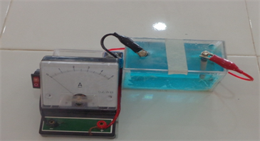
Plate 1. Experimental set up of compact electrolytic cell.
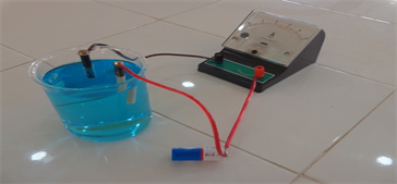
Plate 2. Experimental set up for simulated conventional electrolytic cell.
 (s1)
(s1)
 (s2)
(s2)
 (s3)
(s3)
 (s4)
(s4)
![]() (s5)
(s5)
![]() (s6)
(s6)
Figure 2. Attempted design and construction of compact and durable units of electrolytic cell. Scheme 1: SW isometric view of electrolytic cell; Scheme 2: Top view of electrolytic cell, Keynote: 1) Switch, 2) Electrolytes compartment, 3) Battery (1 piece of 9 V) compartment, 4) Compartment for electrolyte, 5) Opening for dispensing electrolyte, 6) Cathode, 7) Anode, 8) Ammeter, 9) Live conductor, 10) Neutral conductor; Scheme 3: Front view of electrolytic cell; Scheme 4: Back view of electrolytic cell; Scheme 5: Side view of electrolytic cell; Scheme 6: Electrical circuit diagram of electrolytic cell.
![]()
![]() (a) (b)
(a) (b)
Figure 3. Stages of development of electrolytic cell from conventional electrolytic cell to attempted designed and constructed of electrolytic cell. (a) Typical conventional electrolytic cell; (b) Second attempt of designed and constructed electrolytic cell.

Table 1. Differences between conventional and attempted designed and constructed electrolytic cell.
negative effects on the cells if not for the removal of electrodes from the cells electrolytes compartments whenever they were turned upside down which is obvious. The constructed electrolytic cell is compact, durable and portable.
3.1.2. Comparative Study: Conventional vs Constructed Electrolytic Cells
Average experimental mass of electroplated copper electrolyzed by the use of the conventional and compact electrolytic cells at various time of electrolysis is being compared with theoretical mass of electroplated copper in Table 2.
Table 2 shows higher electrogravimetry results of compact electrolytic cell than those of the conventional electrolytic cell relative to the theoretical (actual) mass of electroplated copper.
Figures 4-6 show a comparative curve of experimental mass of electroplated copper electrolyzed by conventional and compact electrolytic cells relative to the
Table 2. Average experimental mass of electroplated copper determined by using conventional, compact electrolytic cells, theoretical mass and total mass of copper electrolyzed by each method.
Note: E.C. = Electrolytic cell.
![]()
Figure 4. Curve of experimental mass of electroplated copper (g) versus time of electrolysis (mins) for conventional, compact electrolytic cells and theoretical values.
theoretical mass of electroplated copper (g) versus time of electrolysis (mins), vertical and horizontal bar charts showing experimental mass of electroplated copper (g) against time of electrolysis (min) and time of electrolysis (min) against experimental mass of electroplated copper (g) for conventional, compact electrolytic cells and theoretical value respectively where length of each bar is proportional to the average experimental mass of electroplated copper it represents.
![]()
Figure 5. Experimental mass of electroplated copper (g) versus time of electrolysis (mins) for conventional, compact electrolytic cells and theoretical values.
![]()
Figure 6. Horizontal bar chart of time of electrolysis (mins) versus experimental mass of electroplated copper for conventional, compact electrolytic cells and theoretical values.
3.1.3. Data Analysis of Conventional and Constructed Electrolytic Cells
Data analysis and statistical tests conducted on data obtained from conventional and constructed electrolytic cells in line with [22] [23] showed that for 6 + 6 − 2 = 10 degree of freedom (d. f) in student t table, t is 2.23 at 95.0% confidence level, 2.76 at 98.0% and 3.17 at 99.0% confidence level. Because tcal(3.52) is greater than ttable(2.23) at 95.0%, (2.76) at 98.0% and (3.17) at 99.0% confidence level, the two methods: conventional and constructed electrolytic cells are not the same that is, they do not significantly agree with each other at 95.5%, 98.0% and 99.0% confidence level. However, at 99.9% confidence level, tcal(3.52) is less than ttable(4.59) therefore there is no significant difference between the two cells therefore, they both agree with each other significantly at 99.9% confidence level with the constructed electrolytic cell electroplating higher mass of copper at each time of electrolysis.
Efficiency or percentage performance of the conventional electrolytic cell was determined according to method reported by [24] to be 85.71% performance while that of the compact electrolytic cell is 92.86% performance and error analysis [25] of conventional and constructed electrolytic cells done shows 14.29 % and 7.15% error respectively.
3.2. Discussion
Plate 1 is an experimental set up of the constructed compact, durable, portable and lidded unit of electrolytic cell providing interference-free electrolytic environment while Plate 2 is an experimental set up of conventional electrolytic cell showing how cumbersome and fragile it is with its vessel containing electrolyte opened hence prone to interference and contamination. The constructed electrolytic cell in Plate 1 is compact, portable and durable unit with lidded electrolyte (s) cell, vessel or compartment. It also has an innovation switch and the electrodes are fixed or immersed into electrolyte (s) through a bore designed to hold them in position. In contrast, the simulated conventional electrolytic cell in Plate 2 is so cumbersome in its arrangement. It is not durable because its vessel is a fragile beaker. It is open ended hence prone to interference and contamination. It has no switch―it operates only when the two electrodes are immersed in the electrolyte (s).
Figure 1 is a typical conventional electrolytic cell showing an opened fragile sample (electrolyte) cell made of glass beakers, shattered electrical wires, detachable or removable ammeter, loosed power source (batteries) and electrodes [7] . At variance to this, Figure 2 shows the designed and constructed compact, durable and portable unit of electrolytic cell made of rigid and non fragile plastic (Perspex) material with lidded electrolyte compartment, organized electrical wires, fixed ammeter, fixable power source (battery), electrodes and an innovated switch. Figure 3 shows stages of development of electrolytic cell from the conventional electrolytic cell to the designed and constructed compact electrolytic cell.
In Table 1, differences between conventional and constructed (compact) electrolytic cells are outlined: while conventional electrolytic cell is cumbersome, constructed electrolytic cell is compact and portable; electrolytes compartment of conventional electrolytic cell is made of fragile beaker which is opened and prone to interference and contamination, electrolytes compartment of constructed electrolytic cell is made of a lidded durable plastic (Perspex) material; electrodes of conventional electrolytic cell are somehow suspended. Merits of compact electrolytic cell are that metal ions are uniformly deposited on cathodes; the use of its innovated switch offers it smooth operation and better results; it also has a facility (compartment) for storing electrodes. Demerit of compact electrolytic cell is that its lid may lead to reflux of any gas that might evolve out of the system. An advantage of conventional electrolytic cell over the compact one is that gasses can easily escape through its open ended vessel even though the electrolyte (s) therein is (are) prone to interference and contamination. However, metal ions do not uniformly deposit on it cathode since its electrodes are somehow, irregularly immersed into electrolytes.
Relationship between mass of electroplated copper and time taken to electrolyze it determined using conventional electrolytic cell in line with [6] procedures show experimental mass of electroplated copper being directly proportional to time of electrolysis. Mass of electroplated copper increased down the table in correspondent to increase in time of electrolysis down the table proportionally and in reverse order up the table. The lowest mass of electroplated copper, 0.02 g was electrolyzed or deposited after 10 mins electrolysis of the aliquot and the highest mass of electroplated copper, 0.22 g was electrolyzed after 60 mins electrolysis of the aliquot. This is in accordance with the First Faraday’s Law of electrolysis reported by [13] [14] which states that the amount of a substance consumed or produced at an electrode in an electrolytic cell is directly proportional to the amount of electricity, Q:Q = current(I) × time(t) that passes through the cell.
It is observed that experimental mass of electroplated copper (g) which is directly proportional to time of electrolysis increased from 10 mins after which 0.02 g copper was electroplated followed by 20 mins, 30 mins, 40 mins, 50 mins and the longest time, 60 mins after which 0.22 g copper was electroplated in the conventional electrolytic cell.
However, relationship between mass of electroplated copper and time taken to electrolyze it studied in accordance to [6] using constructed electrolytic cell also show experimental mass of electroplated copper being directly proportional to time of electrolysis. Mass of electroplated copper increased down the table in correspondent to increase in time of electrolysis down the table proportionally and in reverse order up the table. The lowest mass of electroplated copper, 0.03 g was electrolyzed or deposited after 10 mins electrolysis of the aliquot and the highest mass of electroplated copper, 0.23 g was electrolyzed after 60 mins electrolysis of the aliquot. This is in accordance with first Faraday’s Law of electrolysis reported by [13] [14] which states that the amount of a substance consumed or produced at an electrode in an electrolytic cell is directly proportional to the amount of electricity, Q:Q = current(I) × time(t) that passes through the cell.
It is also observed that experimental mass of electroplated copper (g) which is directly proportional to time of electrolysis increased from 10 mins after which 0.03 g copper was electroplated followed by 20 mins, 30 mins, 40 mins, 50 mins and the longest time, 60 mins after which 0.23 g copper was electroplated in the constructed electrolytic cell. The values of standard deviation shown in Table 2 were calculated by first determining mean (average) of triplicate mass of Cu electroplated at each time of electrolysis using the formula reported by [22] where means mean or average, is summation of the triplicates values of mass of electroplated Cu and n stands for number of replicate values. Thereafter, standard deviation of each triplicate values (mass of electroplated Cu) was calculated based on [22] using the formula where S is standard deviation, which is square root of summation of individual triplicate value minus mean of the triplicate values raised to power 2, divided by number of replicate minus 1, . But standard deviation of theoretical value of mass of Cu is ±0.00 because mass of Cu for each time of electrolysis were not calculated in replicates.
Data analysis and statistical tests conducted on data obtained from conventional and constructed electrolytic cells in line with techniques reported by [22] [23] showed that for 6 + 6 − 2 = 10 degree of freedom (d. f) in student t table, t is 2.23 at 95.0% confidence level, 2.76 at 98.0% and 3.17 at 99.0% confidence level. Because tcal(3.52) is greater than ttable(2.23) at 95.0%, (2.76) at 98.0% and (3.17) at 99.0% confidence level, hence the two methods: conventional and constructed electrolytic cells are not the same that is, they do not significantly agree with each other at 95.5%, 98.0% and 99.0% confidence level. However, at 99.9% confidence level, tcal(3.52) is less than ttable(4.59) therefore there is no significant difference between the two cells therefore, they both agree with each other significantly at 99.9% confidence level with the constructed electrolytic cell electroplating higher or better mass of copper at each time of electrolysis and in total mass of electroplated copper even as this is confirmed by 92.86% performance of the constructed electrolytic cell against 85.71% performance of the conventional electrolytic cell determined by adopting the method reported by [24] . Error analysis of conventional and constructed electrolytic cells is 14.29% and 7.15% error respectively indicating less error in the constructed electrolytic cell.
4. Conclusions
Compact, durable and portable unit of electrolytic cell was designed and constructed using Perspex, a glass like plastic material. Electrolysis was carried out for 10 mins, 20 mins, 30 mins, 40 mins, 50 mins, and 60 mins at 0.2 A using the conventional and constructed electrolytic cells and mass of electroplated copper at each time was deduced. Total experimental mass of electroplated copper electrolyzed using conventional and constructed electrolytic cells is 0.72 g and 0.78 g respectively while theoretical mass of electroplated copper is 0.84 g. Statistical analysis on data obtained from the use of the conventional and constructed electrolytic cells showed that the two methods do not significantly agree with each other hence are not the same at 95.5%, 98.% and 99.0% confidence levels; however, they significantly agree with each other at 99.9% confidence level. Percentage performances of these cells are 85.5% performance for conventional and 92.86% performance for constructed electrolytic cells. Percentage error of conventional and constructed electrolytic cell is 14.29% and 7.15% respectively.
The results of this study buttress that Perspex is a good material for constructing compact, durable and portable electrolytic cells. Compact electrolytic cell provided better results than the conventional cell; that mass of electroplated copper and time of electrolysis have a positive correlation and statistical analysis of data obtained from the conventional and constructed electrolytic cell revealed that the two sets of methods do not agree significantly with each other at 95.00% confidence level but they agree significantly with each other beyond this confidence level to 99.9% confidence level.
Cite this paper
Musa, D.E., Sha’Ato, R., Eneji, I.S. and Itodo, A.U. (2018) Electrogravimetric Determination of Copper Using a Constructed Compact Electrolytic Cell Open Access Library Journal, 5: e4446. https://doi.org/10.4236/oalib.1104446
References
- 1. Bard, A.J. and Faulkner, L.R. (2001) Electrochemical Methods: Fundamentals and Applications. 2nd Edition, Wiley, New York.
- 2. Skoog, D.A., Holler, F.J. and Crouch, S.R. (2007) Principles of Instrumental Analysis. Brooks/Cole, Thomson, Belmont, CA, 1.
- 3. Arikawa, Y. (2001) Basic Education in Analytical Chemistry (Pdf). Analytical Sciences. The Japan Society for Analytical Chemistry, 17, i571-i573.
- 4. Skoog, D.A., Holler, F.J. and Crouch, S.R. (2007) Principles of Instrumental Analysis. Brooks/Cole, Thomson, Belmont, CA, 5.
- 5. Lal, S. (2010) Measurements in Chemistry. 6th Edition, Practice Hall, USA, 4.
- 6. Skoog, D.A., West, D.M., Holler, F.J. and Crouch, S.R. (2014). Fundamentals of Analytical Chemistry. Brooks/Cole, Cengage Learning, Belmont, 1.
- 7. Atkins, P. (2006) Physical Chemistry. 6th Edition, Freeman, W.H. and Company, New York, 100-120.
- 8. Hutchison, D. (2016) Electrochemical Cells: Linking Fields and Currents with Products and Reactants. European Journal of Physics, 37, 30-35.
https://doi.org/10.1088/0143-0807/37/6/065205 - 9. HYPERLINK (2018).
http://www.cranstonelectrolysis.com http://www.cranstonelectrolysis.com - 10. Ezechukwu, J. (2006) Comprehen-sive Chemistry for Senior Secondary Schools. 3rd Edition, A. Johnson Publishers Ltd., Lagos, 109-116, 276.
- 11. Petrucci, R.H., William, S., Herring, F.G. and Madura, J.D. (2007) General Chemistry: Principles and Modern Applications. 9th Edition, Pearson Education, Inc., Upper Saddle River, 80-90.
- 12. Skoog, D.A. and Leary, J.J. (2006) Principles of Instrumental Analysis. 4th Edition, Saunders College Publishers, Fort Worth, 496.
- 13. Haughton, B. (2007) Hidden History; Lost Civilizations, Secret Knowledge and Ancient Mysteries. Career Press, Wayne, NJ, 129-132.
- 14. Barker, D. and Walsh, F.C. (1991) Applications of Faraday’s Laws of Electrolysis in Metal Finishing. Transactions of the Institute of Metal Finishing, 69, 158-162.
https://www.researchgate.net - 15. Mcat (2008) Electrochemistry: Images of Electrochemical Cells.
- 16. Shakerijooybari, B., Moghimi, R., Golgiri, D., Afaride, H., Lamehi, R.M. and Gbergherehchi, M. (2015) Design and Construction of Optimized Electrochemical Cell and Data Analysis for Etching of Ion Tracks and Electro-Deposition of Nano and Micro Wires in Porous Ion Track Foils. Journal of Physics Procedia, 80, 57-61.
https://doi.org/10.1016/j.phpro.2015.11.068 - 17. Oladebeye, D.H. and Balaji, B.O. (2004) Design, Construction and Performance Testing of a Forced Vortex Equipment for Use in the Fluid Mechanics Laboratory. International Journal of Science and Technological Research, 1, 137-144.
- 18. Kwaya, P.V. (2004) Design, Construction and Performance Evaluation of Soya Bean Grinder and Milk Extraction. Savannah Journal of Science and Technology, 1, 53.
- 19. Ubokwe, S.O., Bala, K.C. and Shaba, G. (2004) Design and Construction of Modified Incubator for Poultry Use. Savannah Journal of Science and Technology, 1, 56-58.
- 20. Ghulam, J.Q., Saleem, N.M. and Bhat, A. (2006) Design and Construction of Dialysis Units. JK-Practitioner, 13, 1-4.
- 21. Instruction Guide (2006) Build a Gel Electrophoresis Chamber. University of Utah, Utah, 1-15.
http://learn.genetics.utah.edu/content/labs/gel/build_gel_box.pdf - 22. Harvey, D. (2000) Modern Analytical Chemistry. International Edition, McGraw-Hill Companies, New York, 33-49.
- 23. Frankfort, N.C. and Leon, G.A. (2006) Social Statistics for Diverse Society. Pine Forge Press, Thousand Oaks, 6.
- 24. Dallatu, E.M. and Okorafor, L.M. (2009) Local Preparation of Blue and Red Litmus Papers. International Journal of Chemical Sciences, 2, 228-233.
- 25. Ibitoye, A.A. (2005) Laboratory Manual on Basic Quantitative Chemical Methods and Calculations. 2nd Edition, Publ. Foladave Publishing Company, Akure-Ondo, 7.