Intelligent Control and Automation, 2011, 2, 450-455
doi:10.4236/ica.2011.24051 Published Online November 2011 (http://www.SciRP.org/journal/ica)
Copyright © 2011 SciRes. ICA
Blank Holder Force Control System Driven by
Servo-Motor
Siji Qin, Li Yang, Bing Yang
College of Mechani cal Enineering, Yanshan University, Qinhuangdao, China
E-mail: plastics@ysu.edu.cn
Received September 30, 2011; revised October 28, 2011; accepted November 6, 2011
Abstract
Blank holder force (BHF) control is used to prevent wrinkles of sheet metal in deep drawing process. Based
on a novel conception of BHF control technique driven by servo-motor, a new BHF device with six-bar
linkage mechanism has been designed and manufactured. Whole control system of the new BHF technique
was developed, and the basic structure of the hardware configuration of the system was given. Software
analysis, implementation and division of the functional modules have been done. Also, the control software
in data acquisition and processing module has been developed in the relevant technology of the BHF control
system for the requirements of real-time, stability and accuracy. By the new BHF device combined with the
hardware and the software system, the BHF can be regulated accurately variation with the predefined BHF
profile in deep drawing process.
Keywords: Metal Forming, Blank Holder Force, BHF Control Driven by Servo-Motor, Six-Bar Linkages
1. Introduction
In deep drawing, the blank holder plays a role in regu-
lating the metal flow and when the blank holder forces
(BHF) selected properly, it can eliminate wrinkles and
delay fracture in the drawn part. When the BHF is small,
the sheet metal over the flange area tends to instabilities
and wrinkling because of excessive circumferential stress,
while tensile stress at dangerous section of the sheet
metal will increase and fracture occur due to too large
BHF. Consequently, the BHF is a key parameter during
the process, which should be changed with the punch
stroke and an optimal relationship between BHF and
stoke for a deep drawing process was called reasonable
BHF profile generally [1-3]. The BHF profile can be
predicted by numerical simulations, experimental trials
and analytical research [1,4-6].
Currently, as a result of large transmission ratio and
easy to control, hydraulic transmission is used to imple-
ment the variable BHF profile control system [7-9]. Be-
cause of their size and complexity, slow response time,
control accuracy, and high energy consumption, the hy-
draulic systems are not suitable for precision, numerical
control, flexibility and other requirements in the process
of forming.
A new conception for the BHF control driven by a
servo motor has been proposed [10]. As many advan-
tages such as short transmission chain, simple control
system, numerical control, and so on, this new BHF con-
trol system should be more effective to regulate the BHF
and to improve the quality of forming parts during the
process in comparison with the hydraulic system.
In this paper, according to the BHF control technique
based on servo motor driven and the requirements for the
BHF in deep drawing process, a whole control system,
and its hardware and software have been designed. The
designed open-CNC BHF control system is flexible and
easy to implement, as well as convenient for further de-
velopment and application. Also, a BHF actuator con-
sisting of some parts has been designed and manufac-
tured. In the open-CNC technology, the computer is a
platform of hardware and software of numerical control
system, the motion controller is a key component to con-
trol the servo motor and the BHF actuator, so that the
blank holder would follow certain movement trajectory,
to ensure reasonable BHF profile or other predefined
one.
2. BHF Device Driven by Servo Motor
The structural principle of blank holder device driven by
servo motor is shown in Figure 1. The actuator of the
S. J. QIN ET AL.451
servo motor
coupling
screw
nut
blank holder
connecting r od
slide boar
d
stationary board
six-bar linkage
cushion
Figure 1. Blank holder device with a six-bar linkage.
BHF control system consists of a ball screw and nut pairs,
a six-bar linkage and one blank holder and other parts. In
this case, the leadscrew, driven by a servomotor passing
through a coupling, is supported between two bearings
and housings. The servo motor and the housings are
fixed rigidly on a framework. The nut is driven by the
ball screw and moves in a straight line. Then, the six-bar
linkage driven by the nut passes movement and force to a
slide board moving up and down, which is connected to
the blank holder by four cushions and four connecting
rods. By the six-bar mechanism, the blank holder moves
in straight line by variable speed while the nut moves by
uniform speed. The relationship between output and in-
put displacement of the six-bar linkage designed is
shown in Figure 2, where displacement of the nut and
position of the slide board stand for input and output
respectively. With the six-bar linkage, the blank holder
can be quickly down and slow to load and fast return. In
other words, uneven transmission ratio characteristics of
the six-bar linkage can greatly reduce the rated motor
torque. AC servo motor has a strong overload capacity,
wide speed range, good acceleration and deceleration
performance, frequent starting, braking, reversing switch
and other repetitive motion, so that with a certain power
of the AC servo motor and reasonable parameters of the
BHF actuator, the blank holder can move by following
certain rules and the BHF should vary with the punch
stroke to meet the requirements of deep drawing process.
Figure 3 is a BHF device manufactured, which con-
sists of a six-bar linkage, a blank holder, a slide board,
four connecting rods, and some other parts.
3. BHF Control Hardware System
The implementation and validation of control algorithms
requires a flexible structure in terms of hardware and
150
170
190
210
230
250
270
290
310
020 40 6080100120140
Displacement of the nut (mm)
Position of the slide board (mm)
Figure 2. Displacement relationships between input and
output for the six-bar linkage.
servo motorscrew nutblank ho lder
connec ting r od slide board stationary board
six-bar linkage
cushion
Figure 3. Photo of the blank holder device manufactured.
software. Traditionally, industrial NC systems tasks are
generally related to manipulation, which requires only
controlling the position of the tools or actuators [11], but
in the BHF control, both of the BHF and the position of
the blank holder are required.
BHF control system mainly consists of an industrial
personal computer (IPC), a motion controller, program-
mable multi-axis card (PMAC), an AC servo driv e and a
motor made of Yaskawa, a force sensor, an optical grat-
ing, an on-off control, some I/O ports and power units
and other components, which is a closed-loop control
system (Figure 4).
An IPC-NC hierarchical architecture was used in the
BHF system. As an upper computer of the whole system,
the IPC is responsible for management, supervision, and
control software kernel and background operation.
As a lower computer, the PMAC is a key component
of the whole control system, which provides all the real-
time instructions for processing and orders the lower
Copyright © 2011 SciRes. ICA
S. J. QIN ET AL.
452
Force loo p
Position mod ule
+ +
Posi tion loop
A/D Servo motor
BHF module
Actuator
Predefined fo r ce Predefined posit ion
Fo rce sen sor Op tic a l gra ting
Figure 4. BHF control system block diagram.
control unit simultaneously to cooperate the motion con-
trol. The selected PMAC is a 4-axis motion control card,
in which, by using high-speed DSP, the CPU has strong
programmable logic controlled (PLC) and motion control
functions. In the four axes of the PMAC, one is used for
the drive of the servo motor and manipulating the BHF
actuator, another is for a position control of the press
slider. The remaining two can be reserved for develop-
ment of the system control, one of which may be used
for servo feed mechanism in the future.
There are many application examples using PMAC
[12-15], some of them involving in force control [14-15].
In the BHF control system, the blank holder position
signals feedback from optical grating an d access the mo-
tion controller, while the BHFs, analog signals, which
are acquired by the BHF sensor, are turned into digital
signals by A/D converter and processed by filter-ampli-
fier, and then access to the motion controller as feedback
signals, and both of the force signals and the position
signals are used to realize real-time detection and closed-
loop control.
4. BHF Control Software System
4.1. BHF Control Strategy
According to the characteristics of deep drawing process,
a composite mode of position control and force control
was used. Shown in Figure 5, there are two stages in the
whole deep drawing process, one of which is idle stroke,
at this time the punch of the press moves up or down fast,
and the other is effective work stroke(corresponding to
AB segment shown in Figure 5), now the punch moves
down slowly. The blank holder should moves rapidly and
slowly respectively during the idle stroke and the effect-
tive work stroke of the punch. When the punch and the
blank holder move down, the latter must touch the sheet
metal first before the former. During the idle stroke, po-
sition manipulating was used in the BHF control system
Blank h older force
Time
O A B
Figure 5. Diagram of BHF versus time.
mainly considering time and efficiency requirements,
while during the effective work stroke, blank holder
force regulating was used in the BHF system because of
the requirements of accurate BHF control.
By programming composition of motion control and
directly sending commands to the location of the motion
controller, through it the commands are transmitted to
the drive and th e servo motor, and the blank ho lder force
actuator is driven to achieve the movement of the blank
holder, so th e position control mode can be realized dur-
ing idle stroke stage. When the blank holder force sensor
detects the signal output is greater than the set value, the
control mode is converted from position control to force
one. The difference between the BHF detected by the
sensor and preset one was input as feedback for closed-
loop control.
4.2. Components of the BHF Software System
BHF control software system consists of non-real-time
and real-time control modules. The PC is in charge of the
non-real-time motion control, such as non-real-time
management, easy operation with the man-machine in-
terface, initialization of the entire BHF system, setting
the system parameters, non-real-time display, etc.
For example, a communication module, as non-real-
time module, play a role of communication between the
PC and the PMAC based on the ethernet technology, by
sending online instruction s from PComm32 dynamic lin k
library to the PMAC to con duct communication and data
exchange to realize the whole control for the system.
Another example of the non-real-time module is
human-computer interaction, which has been realized
through human-machine interface, and users and the
blank holder force control system can exchange informa-
tion, such as control mode selection, setting of the rea-
sonable BHF profile, speed and location information,
displays of the information feedback and working condi-
tions. The users can operate through the software inter-
face, and reliable man-machine interface ensure proper
use of system, as well as the data and program security.
Human-machine interface software program was de-
Copyright © 2011 SciRes. ICA
S. J. QIN ET AL.
Copyright © 2011 SciRes. ICA
453
veloped by VC++ 6.0 in Windows XP environment.
Dynamic link library Pcomm32 was called to realize
performances of the motion controller, because API
functions in Windows XP have no direct access to the
motion controller.
The developed control system main in terface is shown
in Figure 6.
For example, in the control program for the realization
communication between the motion controller and the
host computer, the follow codes were written as
CMainFrame::CMainFrame()
{
hMydll=LoadLibrary(“Pcomm32.dll”);
//applied in Pcomm32Pro
if(hMydll==NULL)
AfxMessageBox(“PMAC Failed to open dll”);
open=(OpenPmac)GetProcAddress(hMydll,
“OpenPmacDevice”);
}
For real-time control in deep drawing process, the real
instantaneous position of the blank holder and the BHF
are detected in time and as feedback signals which are
compared with predefined values. Then, adjustment sig-
nals of the BHF are sent to the drive, so the mechanical
actuators can be driven by the servo motor for the
closed-loop control.
The performance of the BHF control system depends
mainly on the application and development of the soft-
ware. As a result, it is necessary to develop the BHF
control system software considering its own characteris-
tics.
The performance of the real-time control module of
the lower computer mainly includes interpolation, posi-
tion control, BHF acquisition and control, etc. (Figure
7).
The interpolation control and the position control have
been encapsulated in the motion control card. This col-
lection focuses on the BHF and its control module. The
following focuses on acquisition and control of the BHF.
The following is an example of PLC program for data
acquisition:
CLOSE ; Make sure all buffers are closed
DEL ETE GA THER ; Erase any defined gather buff er
OPEN PLC10 ; Open buffer for progr am entr y
CL EAR ; Erase existing contents of the buffer
P100 = 0 ; Initialization of initial variable
P110 = 0 ; Initialization of BHF
WHILE ( P100 ! < 5) ;To 5 times if not
P110 = P110+ M502 ; BHF accumulation
ENDWHILE;
P111 = P110/ 5 ; Assignment after averaging
IF ( P111 ! < 2.0) DISABL E PLC10; If the BHF is
less than a set value, then close
WHILE ( P10 ! < 10) ; End loop
CLOSE ; Close Buffer
Figure 6. The main interface control system.
S. J. QIN ET AL.
Copyright © 2011 SciRes. ICA
454
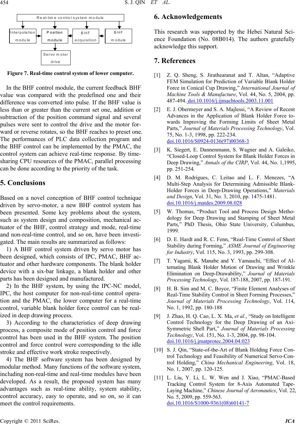
R eal-time co ntrol s ystem m odule
Interpola tion
m odule
Servo motor
drive
BHF
m odule
BHF
acquisition
Position
m odu le
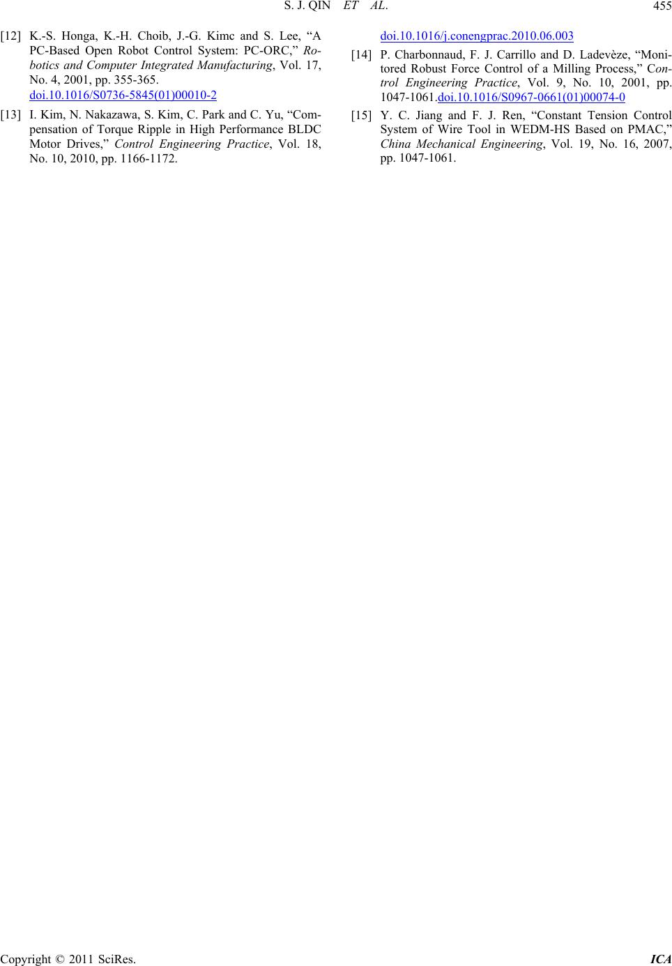
Figure 7. Real-time control system of lower computer.
In the BHF control module, the current feedback BHF
value was compared with the predefined one and their
difference was converted into pulse. If the BHF value is
less than or greater than the current set one, addition or
subtraction of the position command signal and several
pulses were sent to control the drive and the motor for-
ward or reverse ro tates, so the BHF reaches to preset one.
The performances of PLC data collection program and
the BHF control can be implemented by the PMAC, the
control system can achieve real-time response. By time-
sharing CPU resources of the PMAC, parallel processing
can be done according to the priority of the task.
5. Conclusions
Based on a novel conception of BHF control technique
driven by servo-motor, a new BHF control system has
been presented. Some key problems about the system,
such as system design and composition, mechanical ac-
tuator of the BHF, control strategy and mode, real-time
and non-real-time control, and so on, have been investi-
gated. The main results are summarized as follows:
1) A BHF control system driven by servo motor has
been designed, which consists of IPC, PMAC, BHF ac-
tuator and other hardware components. The blank holder
device with a six-bar linkage, a blank holder and other
parts has been des i g ned and manuf actured.
2) In the BHF system, by using the IPC-NC model,
IPC, the host computer for non-real-time control opera-
tion and the PMAC, the lower computer for a real-time
control, variable blank holder force control can be real-
ized in deep drawi n g p r ocess.
3) According to the characteristics of deep drawing
process, a composite mode of position control and force
control has been used in the BHF system. The position
control and force control were corresponding to the idle
stroke and effective work stroke respectively.
4) The BHF software system has been designed by
modular method. Many functions of the software system,
including non-real-time and real-time modules have been
developed. As a result, the proposed system has many
advantages such as real-time ability, system stability,
control accuracy, easy to operate, and so on, so it can
meet the control requirements.
6. Acknowledgements
This research was supported by the Hebei Natural Sci-
ence Foundation (No. 08B014). The authors gratefully
acknowledge this suppor t.
7. References
[1] Z. Q. Sheng, S. Jirathearanat and T. Altan, “Adaptive
FEM Simulation for Prediction of Variable Blank Holder
Force in Conical Cup Drawing,” International Journal of
Machine Tools & Manufacture, Vol. 44, No. 5, 2004, pp.
487-494. doi.10.1016/j.ijmachtools.2003.11.001
[2] E. J. Obermeyer and S. A. Majlessi, “A Review of Recent
Advances in the Application of Blank Holder Force to-
wards Improving the Forming Limits of Sheet Metal
Parts,” Journal of Materials Processing Technology, Vol.
75, No. 1-3, 1998, pp. 222-234.
doi.10.1016/S0924-0136(97)00368-3
[3] K. Siegert, E. Dannenmann, S. Wagner and A. Galeiko,
“Closed-Loop Control System for Blank Holder Forces in
Deep Drawing,” Annals of the CIRP, Vol. 44, No. 1,1995,
pp. 251-254.
[4] D. M. Rodrigues, C. Leitao and L. F. Menezes, “A
Multi-Step Analysis for Determining Admissible Blank-
Holder Forces in Deep-Drawing Operations,” Materials
and Design, Vol. 31, No. 3, 2010, pp. 1475-1481.
doi.10.1016/j.matdes.2009.08.028
[5] W. Thomas, “Product Tool and Process Design Metho-
dology for Deep Drawing and Stamping of Sheet Metal
Parts,” PhD Thesis, Ohio State University, Columbus,
1999.
[6] D. E. Hardt and R. C. Fenn, “Real-Time Control of Sheet
Stability during Forming,” ASME Journal of Engineering
for Industry, Vol. 115, No. 3, 1993, pp. 299-308.
[7] T. Yagami, K. Manabe and Y. Yamauchi, “Effect of Al-
ternating Blank Holder Motion of Drawing and Wrinkle
Elimination on Deep-Drawability,” Journal of Materials
Processing Technology, Vol. 187-188, 2007, pp. 187-191.
[8] H. B. Sim and M. C. Boyce, “Finite Element Analyses of
Real-Time Stability Control in Sheet Forming Processes,”
Journal of Materials Processing Technology, Vol. 114,
No. 1, 1992, pp. 180-188
[9] J. Zhao, H. Q. Cao, L. X. Ma, et al., “Study on Intelligent
Control Technology for the Deep Drawing of an Axi-
Symmetric Shell Part,” Journal of Materials Processing
Technology, Vol. 151, No. 1-3, 2004, pp. 98-104.
doi.10.1016/j.jmatprotec.2004.04.023
[10] S. J. Qin, “State-of-the-Art of Blank Holding Force Con-
trol Technology and Feasibility of Numerical Servo-Con-
trol Holding,” China Mechanical Engineering, Vol. 18,
No. 1, 2007, pp. 120-125.
[11] L. Liu, Y. Li, L. W. Wen and J. Xiao, “PMAC-Based
Tracking Control System for 8-Axis Automated Tape-
Laying Machine,” Chinese Journal of Aeronautics, Vol. 22,
No. 5, 2009, pp. 559-563.
doi.10.1016/S1000-9361(08)60141-7
S. J. QIN ET AL.455
[12] K.-S. Honga, K.-H. Choib, J.-G. Kimc and S. Lee, “A
PC-Based Open Robot Control System: PC-ORC,” Ro-
botics and Computer Integrated Manufacturing, Vol. 17,
No. 4, 2001, pp. 355-365.
doi.10.1016/S0736-5845(01)00010-2
[13] I. Kim, N. Nakazawa, S. Kim, C. Park and C. Yu, “Com-
pensation of Torque Ripple in High Performance BLDC
Motor Drives,” Control Engineering Practice, Vol. 18,
No. 10, 2010, pp. 1166-1172.
doi.10.1016/j.conengprac.2010.06.003
[14] P. Charbonnaud, F. J. Carrillo and D. Ladevèze, “Moni-
tored Robust Force Control of a Milling Process,” Con-
trol Engineering Practice, Vol. 9, No. 10, 2001, pp.
1047-1061.doi.10.1016/S0967-0661(01)00074-0
[15] Y. C. Jiang and F. J. Ren, “Constant Tension Control
System of Wire Tool in WEDM-HS Based on PMAC,”
China Mechanical Engineering, Vol. 19, No. 16, 2007,
pp. 1047-1061.
Copyright © 2011 SciRes. ICA