Int. J. Communications, Network and System Sciences, 2011, 4, 696-703
doi:10.4236/ijcns.2011.411085 Published Online November 2011 (http://www.SciRP.org/journal/ijcns)
Copyright © 2011 SciRes. IJCNS
High-Gain Array Antenna Based on Composite
Right/Left-Handed Transmission Line
Ningli Zhu, Quanyuan Feng, Zhi-Ang Wu
Institute of Microelectronics, Southwest Jiaotong University, Chengdu, China
E-mail: bk20082582@my.swjtu.edu.cn
Received August 20, 2011; revised September 19, 2011; accepted September 27, 2011
Abstract
In this paper a metamaterial-inspired antenna with high gain and good directivity is designed. Based on the
concept of composite right/left-handed transmission line (CRLH-TL), the proposed antenna is realized based
on three leakage wave unit cell and a left handed circular ring slot incorporated on the surface. The maxi-
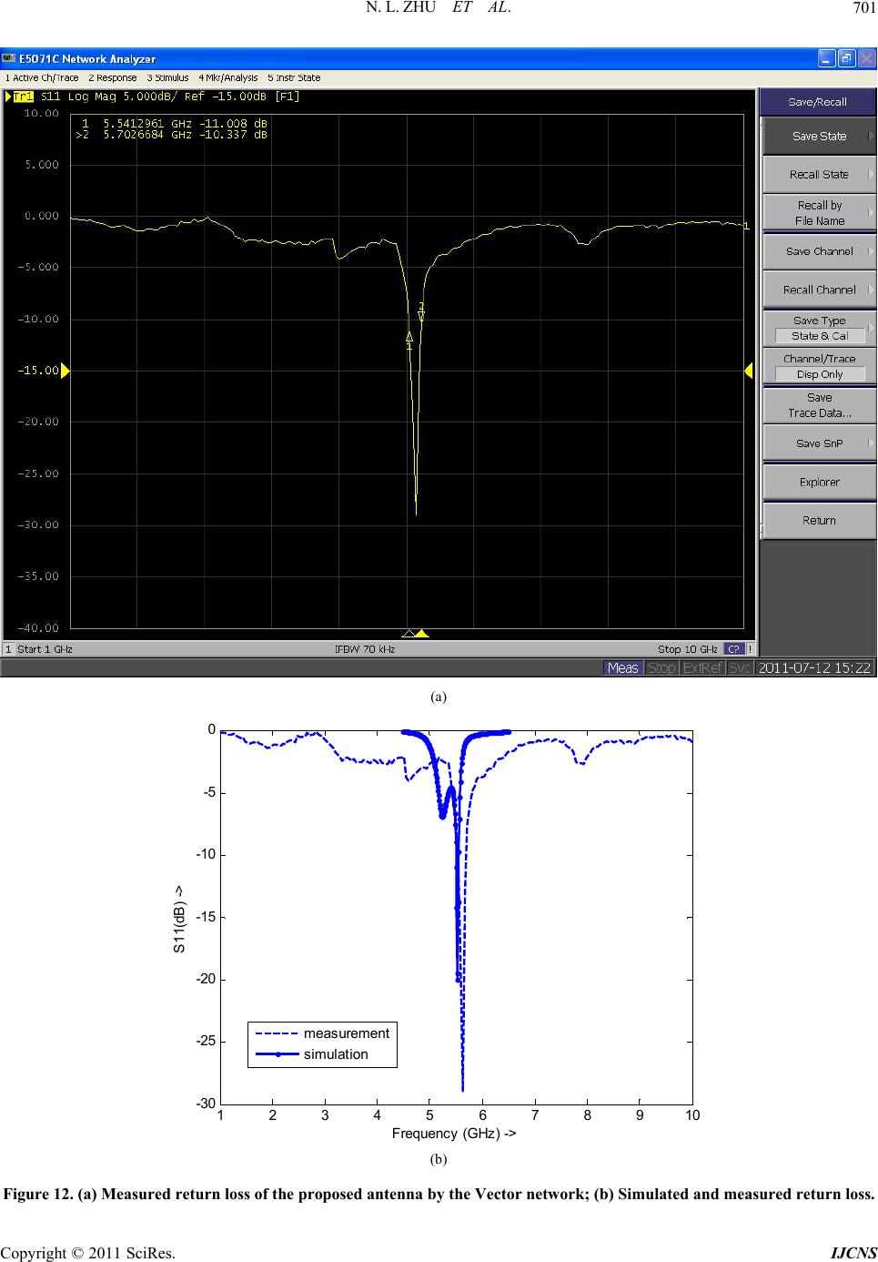
mum achievable gain at the resonant frequency of 5.6 GHz is 6.933 dBi, and the return loss at 5.6 GHz can
be –20 db. This proposed design has a simple structure and a compact dimension of 35 mm*40 mm*1 mm,
which is suitable for particular wireless communication application such as WiFi and WLAN.
Keywords: Composite Right/Left-Handed CRLH, Array Structure, High-Gain
1. Introduction
Electromagnetic metamaterials are effectively homoge-
neous artificial structures engineered to provide electro-
magnetic properties not readily observable in nature,
such as, an index of refraction that may be negative, less
than one, or modulated in a graded manner [1]. Particu-
larly, LH metamaterials has made it possible to realize
novel microwave applications such as small resonant
antennas, dominant-mode leaky-wave antennas, negative
refractive index lenses, and dual-band components which
are not possible before [2]. The significance of LH meta-
materials to both the engineering and scientific commu-
nities has sparked lots of formation of international con-
ferences dedicated to metamaterial research, their appli-
cations, publication of many books, and so on and so forth.
As the everlasting demand for faster and more com-
pact electronic devices, composite right/left-handed
(CRLH) transmission line metamaterials [3], with their
rich dispersion information and excellent directivity,
have received significant concern and led to numerous
novel multifunctional and compact microwave applica-
tions over the past decade, especially on antennas. Vari-
ous practical leaky-wave [4,5] and resonant-type CRLH
antennas have been designed, and often the resonant-type
antennas offer more alternative properties like multi-
band operation, zeroth-over high efficiency, good direc-
tivity, but suffers from narrow bandwidth. There are a lot
of difficulties in achieving a broad bandwidth while
keeping a solid ground.
This paper explores the possibility of designing a high
gain and directive antenna with a solid ground inspired
by the composite right/left-handed (CRLH) transmission
line metamaterials concept. All the antenna parameters,
such as the return loss, gain, are provided in detail.
2. Configuration and Working Principle
2.1. Configuration
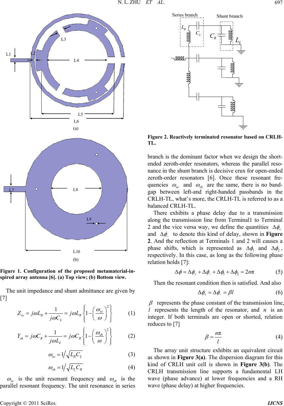
Figure 1 shows the configuration of the proposed an-
tenna. The antenna is implemented on an f4b-2 substrate
with a thickness of 1 mm and a relative permittivity of
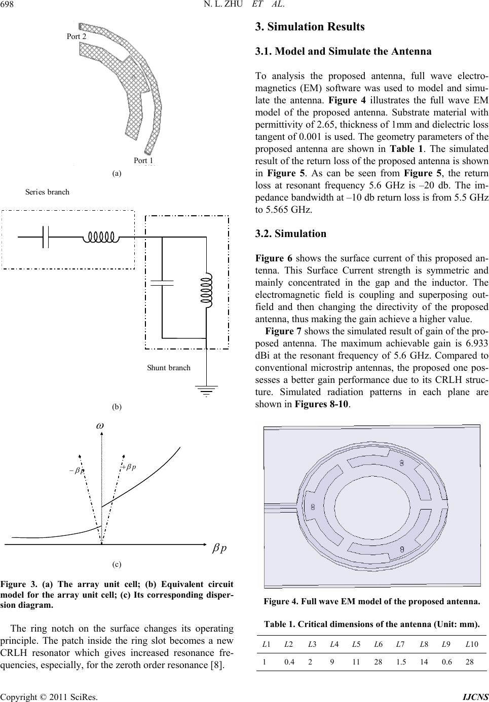
2.65. It consists of three unit cells as show in the Figure
2. A circle ring notch is made on the metal surface. This
antenna is fed by a piece of 50 Ohm microstrip line in
the way of edge coupling.
2.2. Working Principle
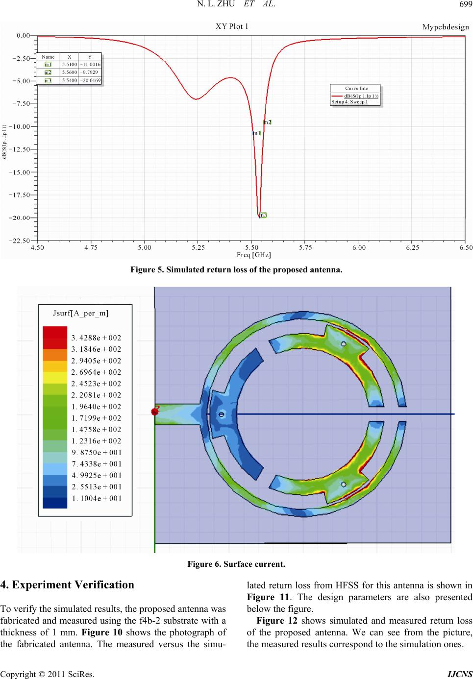
The array structure is essentially a CRLH structure as
discussed in [3]. The slot between the unit cells and the
circular feed line acts as the left-handed (LH) series ca-
pacitor. This via in the unit cell center plays the role of
the shunt inductance. They correspond to the LH contri-
bution. The right-handed (RH) contribution comes from
the distributed series inductance and distributed shunt
capacitance.
N. L. ZHU ET AL.697
L1 L2
L3
L4
L5
L6
(a)
L7
L10
L8
L9
(b)
Figure 1. Configuration of the proposed metamaterial-in-
spired array antenna [6]. (a) Top view; (b) Bottom view.
The unit impedance and shunt admittance are given by
[7]
2
11se
se RR
L
ZjL jL
jC




 




(1)
2
11sh
sh RR
L
YjC jC
jL




 




(2)
1
s
eR
LC
L
(3)
1
s
hL
LC
R
(4)
s
e
is the unit resonant frequency and
s
h
is the
parallel resonant frequency. The unit resonance in series
L
C
R
L
Shunt branch
R
C
L
L
Series branch
Figure 2. Reactively terminated resonator based on CRLH-
TL.
branch is the dominant factor when we design the short-
ended zeroth-order resonators, whereas the parallel reso-
nance in the shunt branch is decisive crux for open-ended
zeroth-order resonators [6]. Once these resonant fre-
quencies
s
e
and
s
h
are the same, there is no band-
gap between left-and right-handed passbands in the
CRLH-TL, what’s more, the CRLH-TL is referred to as a
balanced CRLH-TL.
There exhibits a phase delay due to a transmission
along the transmission line from Terminal1 to Terminal
2 and the vice versa way, we define the quantities
and
to denote this kind of delay, shown in Figure
2. And the reflection at Terminals 1 and 2 will causes a
phase shifts, which is represented as 1
and 2
,
respectively. In this case, as long as the following phase
relation holds [7]:
12
2πn


 (5)
Then the resonant condition then is satisfied. And also
l


  (6)
represents the phase constant of the transmission line,
represents the length of the resonator, and is an
integer. If both terminals are open or shorted, relation
reduces to [7]
ln
πn
l
(4)
The array unit structure exhibits an equivalent circuit
as shown in Figure 3(a). The dispersion diagram for this
kind of CRLH unit cell is shown in Figure 3(b). The
CRLH transmission line supports a fundamental LH
wave (phase advance) at lower frequencies and a RH
wave (phase delay) at higher frequencies.
Copyright © 2011 SciRes. IJCNS
N. L. ZHU ET AL.
698
Port 1
P
ort 2
(a)
Shunt branch
Series branch
(b)
p
p
p
(c)
Figure 3. (a) The array unit cell; (b) Equivalent circuit
model for the array unit cell; (c) Its corresponding disper-
sion diagram.
The ring notch on the surface changes its operating
principle. The patch inside the ring slot becomes a new
CRLH resonator which gives increased resonance fre-
quencies, especially, for the zeroth order resonance [8].
3. Simulation Results
3.1. Model and Simulate the Antenna
To analysis the proposed antenna, full wave electro-
magnetics (EM) software was used to model and simu-
late the antenna. Figure 4 illustrates the full wave EM
model of the proposed antenna. Substrate material with
permittivity of 2.65, thickness of 1mm and dielectric loss
tangent of 0.001 is used. The geometry parameters of the
proposed antenna are shown in Table 1. The simulated
result of the return loss of the proposed antenna is shown
in Figure 5. As can be seen from Figure 5, the return
loss at resonant frequency 5.6 GHz is –20 db. The im-
pedance bandwidth at –10 db return loss is from 5.5 GHz
to 5.565 GHz.
3.2. Simulation
Figure 6 shows the surface current of this proposed an-
tenna. This Surface Current strength is symmetric and
mainly concentrated in the gap and the inductor. The
electromagnetic field is coupling and superposing out-
field and then changing the directivity of the proposed
antenna, thus making the gain achieve a higher value.
Figure 7 shows the simulated result of gain of the pro-
posed antenna. The maximum achievable gain is 6.933
dBi at the resonant frequency of 5.6 GHz. Compared to
conventional microstrip antennas, the proposed one pos-
sesses a better gain performance due to its CRLH struc-
ture. Simulated radiation patterns in each plane are
shown in Figures 8-10.
Figure 4. Full wave EM model of the proposed antenna.
Table 1. Critical dimensions of the antenna (Unit: mm).
L1 L2 L3L4L5L6 L7 L8 L9 L10
1 0.4 2 9 11 28 1.5 14 0.6 28
Copyright © 2011 SciRes. IJCNS
N. L. ZHU ET AL.
Copyright © 2011 SciRes. IJCNS
699
Figure 5. Simulated return loss of the proposed antenna.
Figure 6. Surface current.
4. Experiment Verification
To verify the simulated results, the proposed antenna was
fabricated and measured using the f4b-2 substrate with a
thickness of 1 mm. Figure 10 shows the photograph of
the fabricated antenna. The measured versus the simu-
lated return loss from HFSS for this antenna is shown in
Figure 11. The design parameters are also presented
below the figure.
Figure 12 shows simulated and measured return loss
of the proposed antenna. We can see from the picture,
the measured results correspond to the simulation ones.
N. L. ZHU ET AL.
700
Figure 7. Simulated gain of the proposed antenna.
Figure 8. Simulated radiation patterns in the x-z plane.
Figure 9. Simulated radiation patterns in the x-y plane.
Figure 10. Simulated radiation patterns in the y-z plane.
(a)
(b)
Figure 11. Photograph of the fabricated antenna inspired
by composite right/left handed transmission line. (a) Top
iew; (b) Bottom view. v
Copyright © 2011 SciRes. IJCNS
N. L. ZHU ET AL.
Copyright © 2011 SciRes. IJCNS
701
(a)
12345678910
-30
-25
-20
-15
-10
-5
0
Frequenc y (GHz ) ->
S 11(dB ) ->
measurement
simulation
(b)
Figure 12. (a) Measured return loss of the proposed antenna by the Vector network; (b) Simulated and measured return loss.
N. L. ZHU ET AL.
702
Figure 13. The measured antenna gain is 3.99 dBi at 5.6 GHz.
Figure 13 shows the gain for the antenna. It is noted
that since the zeroth order resonance is generated by the
inner patch inside the slot, the radiation at this frequency
mainly goes to the broadside which is different from tra-
ditional zeroth order resonance antenna. This is due to
the fact that the electrical field exists inside the ring slot
which leads to a horizontal polarization. The measured
antenna gain is 3.99 dBi at 5.6 GHz, a little different
with the 6.93 dBi in the simulation. This may due to the
limitation of fabrication technology.
5. Conclusions
In this paper, a high gain and directive antenna inspired
by composite right/left handed transmission line is suc-
cessfully achieved. We can apply this small array
structure for particular wireless communication use such
as WiFi and WLAN. A simple circle ring notch is made
on the surface which creates an inner CRLH patch and
an outside microstrip patch. The working principle of
this antenna is provided. Simple structure, high gain and
good directivity make this antenna attractive for practical
applications.
6. Acknowledgements
The work is supported by the National Natural Science
Foundation of China (NSFC) under Grant 60990320,
60990323, and the engineering practice project of South-
west Jiaotong University. The authors would like to thank
Qianyin Xiang for his continuous assistance.
7. References
[1] C. Caloz, T. Itoh and A. Rennings, “CRLH Metamaterial
Leaky-Wave and Resonant Antennas,” IEEE Antennas
and Propagation Magazine, Vol. 50, No. 5, 2008, pp. 25-
39. doi:10.1109/MAP.2008.4674709
[2] C. Kittle, “Introduction to Solid State Physics,” 7th Edi-
tion, Wiley Text Books, New York, 1964.
Copyright © 2011 SciRes. IJCNS
N. L. ZHU ET AL.703
[3] C. Caloz and T. Itoh, “Electromagnetic Metamaterials:
Transmission Line Theory and Microwave Applications,”
Wiley-IEEE Press, New York, 2005.
doi:10.1002/0471754323
[4] Y. Dong and T.Itoh, “Composite Right/Left- Handed
Substrate Integrated Waveguide and Hald Mode Sub-
strate Integrated,” IEEE Transmission on Antennas and
Propagation, Vol. 59, No. 3, 2011, pp. 767-775.
doi:10.1109/TAP.2010.2103025
[5] Y. Dong and T. Itoh, “Realization of a Composite Right/
Left-Handed Leaky-Wave Antenna with Circular Polariza-
tion,” 2010 Asia-Pacific Microwave Conference Pro-
ceedings, Yokoh a m a , 7-10 December 2010, pp. 865-868.
[6] Y. Dong and T. Itoh, “Metamaterial-Inspired Broadband
Mushroom Antenna,” 2010 IEEE Antennas and Propa-
gation Society International Symposium, Toronto, 11-17
July 2010, pp. 1-4. doi:10.1109/APS.2010.5560998
[7] T. Ueda, G. Haida and T. Itoh, “Zeroth-Order Resonators
with Variable Reactance Loads at Both Ends,” IEEE
Transmission on Microwave Theory and Techniques, Vol.
59, No. 3, 2011, pp. 612-618.
doi:10.1109/TMTT.2010.2103087
[8] A. Sanada, C. Caloz and T. Itoh, “Zeroth-Order Reso-
nance in Composite Right/Left Handed Transmission
Line Resonators,” IEEE Transactions on Microwave
Theory and Techniques, Vol. 59, No. 3, March 2003, pp.
1588-1592.
Copyright © 2011 SciRes. IJCNS