Paper Menu >>
Journal Menu >>
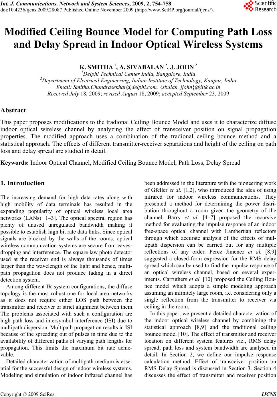 Int. J. Communications, Network and System Sciences, 2009, 2, 754-758 doi:10.4236/ijcns.2009.28087 blished Online November 2009 (http://www.SciRP.org/journal/ijcns/). Copyright © 2009 SciRes. IJCNS Pu Modified Ceiling Bounce Model for Computing Path Loss and Delay Spread in Indoor Optical Wireless Systems K. SMITHA 1, A. SIVABALAN 2, J. JOHN 2 1Delphi Technical Center India, Bangalore, India 2Department of Electrical Engineering, Indian Institute of Technology, Kanpur, India Email: Smitha.Chandrasekhar@delphi.com, {sbalan, jjohn}@iitk.ac.in Received July 18, 2009; revised August 18, 2009; accepted September 23, 2009 Abstract This paper proposes modifications to the tradional Ceiling Bounce Model and uses it to characterize diffuse indoor optical wireless channel by analyzing the effect of transceiver position on signal propagation properties. The modified approach uses a combination of the tradional ceiling bounce method and a statistical approach. The effects of different transmitter-receiver separations and height of the ceiling on path loss and delay spread are studied in detail. Keywords: Indoor Optical Channel, Modified Ceiling Bounce Model, Path Loss, Delay Spread 1. Introduction The increasing demand for high data rates along with high mobility of data terminals has resulted in the expanding popularity of optical wireless local area networks (LANs) [1–3]. The optical spectral region has plenty of unused unregulated bandwidth making it possible to establish high bit rate data links. Since optical signals are blocked by the walls of the rooms, optical wireless communication systems are secure from eaves- dropping and interference. The square law photo detector used at the receiver end is always thousands of times larger than the wavelength of the light and hence, multi- path propagation does not produce fading in a direct detection system. Among different IR system configurations, the diffuse topology is the most robust one for local area networks as it does not require either LOS path between the transmitter and receiver or strict alignment between them. The problems associated with such a configuration are high path loss and intersymbol interference (ISI) due to multipath dispersion. Multipath propagation results in ISI because of the spreading out of pulses in time due to the availability of different paths of varying path lengths for propagation. This limits the maximum bit rate achie- vable. Detailed characterization of multipath medium is esse- ntial for the successful design of indoor wireless systems. Modeling and simulation of indoor infrared channel has been addressed in the literature with the pioneering work of Gfeller et al. [1,2], who introduced the idea of using infrared for indoor wireless communications. They presented a method for determining the power distri- bution throughout a room given the geometry of the channel. Barry et al. [4–7] proposed the recursive method for evaluating the impulse response of an indoor free-space optical channel with Lambertian reflectors through which accurate analysis of the effects of mul- tipath dispersion can be carried out for any multiple reflections of any order. Perez Jimenez et al. [8,9] suggested a closed-form expression for the RMS delay spread which can be used to find the impulse response of an optical wireless channel, based on several exper- iments. Carruthers et al. [10] proposed the Ceiling Bou- nce model which adopts a simple modeling approach assuming an infinitely large room, i.e. considering only a single reflection from the transmitter to receiver via ceiling in the room. In this paper, we present a detailed characterization of the indoor optical wireless channel by combining the statistical approach [8,9] and the traditional ceiling bounce model [10]. The effect of transmitter and receiver location on different system features viz., RMS delay spread, path loss and system bandwidth are analysed in detail. In Section 2, we define our impulse response calculation method. Effect of transceiver position on RMS Delay Spread is discussed in Section 3. Section 4 discusses the effect of transmitter and receiver position 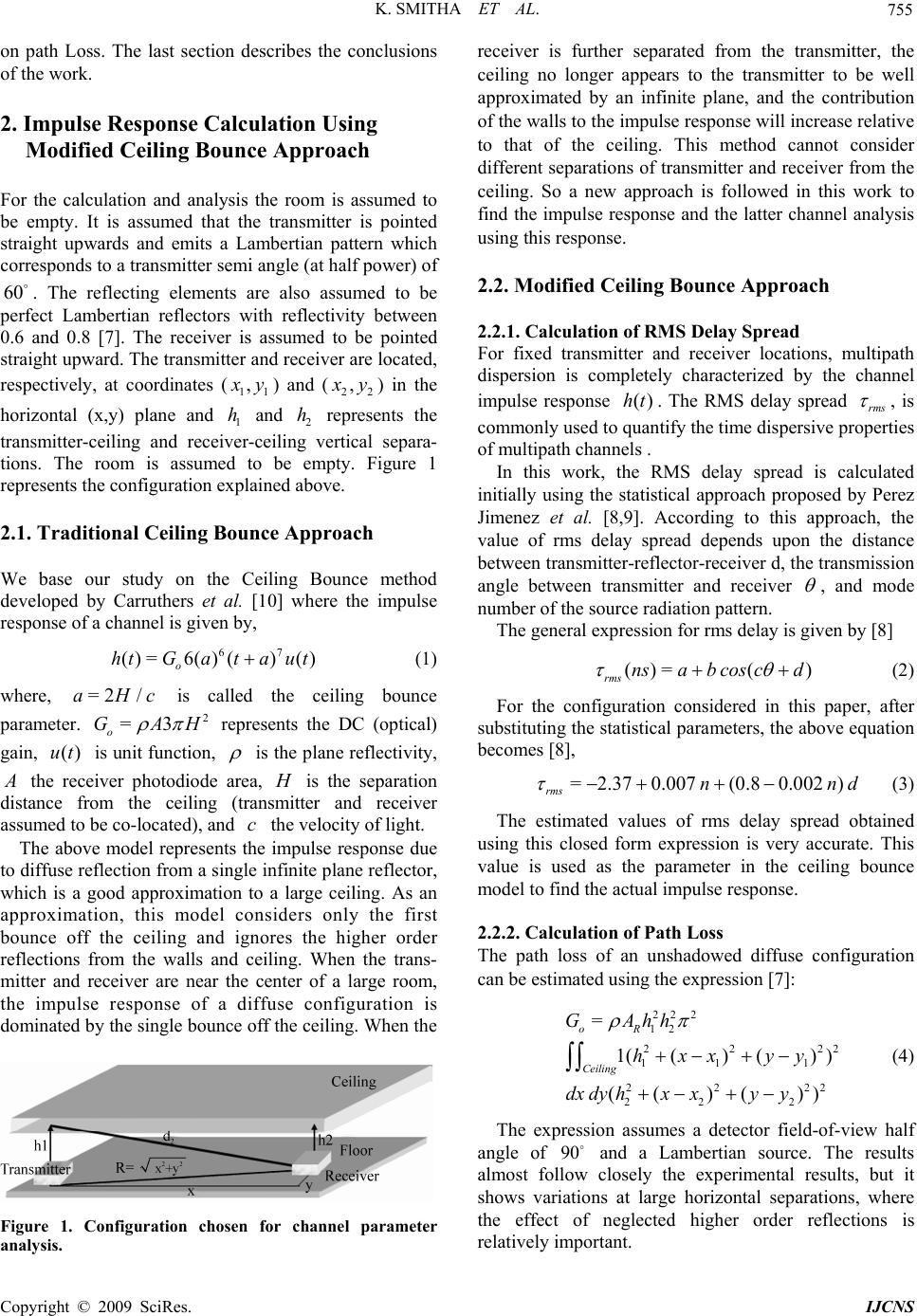 K. SMITHA ET AL. 755 on path Loss. The last section describes the conclusions of the work. 2. Impulse Response Calculation Using Modified Ceiling Bounce Approach For the calculation and analysis the room is assumed to be empty. It is assumed that the transmitter is pointed straight upwards and emits a Lambertian pattern which corresponds to a transmitter semi angle (at half power) of . The reflecting elements are also assumed to be perfect Lambertian reflectors with reflectivity between 0.6 and 0.8 [7]. The receiver is assumed to be pointed straight upward. The transmitter and receiver are located, respectively, at coordinates ( 60 11 , x y) and (22 , x y) in the horizontal (x,y) plane and and represents the transmitter-ceiling and receiver-ceiling vertical separa- tions. The room is assumed to be empty. Figure 1 represents the configuration explained above. 1 h2 h 2.1. Traditional Ceiling Bounce Approach We base our study on the Ceiling Bounce method developed by Carruthers et al. [10] where the impulse response of a channel is given by, 67 ()=6( )()() o htGata ut (1) where, is called the ceiling bounce parameter. represents the DC (optical) gain, is unit function, =2 /aH =3 o GA ()ut c 2 H is the plane reflectivity, A the receiver photodiode area, is the separation distance from the ceiling (transmitter and receiver assumed to be co-located), and the velocity of light. H c The above model represents the impulse response due to diffuse reflection from a single infinite plane reflector, which is a good approximation to a large ceiling. As an approximation, this model considers only the first bounce off the ceiling and ignores the higher order reflections from the walls and ceiling. When the trans- mitter and receiver are near the center of a large room, the impulse response of a diffuse configuration is dominated by the single bounce off the ceiling. When the Figure 1. Configuration chosen for channel parameter analysis. receiver is further separated from the transmitter, the ceiling no longer appears to the transmitter to be well approximated by an infinite plane, and the contribution of the walls to the impulse response will increase relative to that of the ceiling. This method cannot consider different separations of transmitter and receiver from the ceiling. So a new approach is followed in this work to find the impulse response and the latter channel analysis using this response. 2.2. Modified Ceiling Bounce Approach 2.2.1. Calculation of RMS Delay Spread For fixed transmitter and receiver locations, multipath dispersion is completely characterized by the channel impulse response . The RMS delay spread ()ht rms , is commonly used to quantify the time dispersive properties of multipath channels . In this work, the RMS delay spread is calculated initially using the statistical approach proposed by Perez Jimenez et al. [8,9]. According to this approach, the value of rms delay spread depends upon the distance between transmitter-reflector-receiver d, the transmission angle between transmitter and receiver , and mode number of the source radiation pattern. The general expression for rms delay is given by [8] ()= () rmsnsab coscd (2) For the configuration considered in this paper, after substituting the statistical parameters, the above equation becomes [8], =2.370.007 (0.80.002 ) rms nn d 22 2 (3) The estimated values of rms delay spread obtained using this closed form expression is very accurate. This value is used as the parameter in the ceiling bounce model to find the actual impulse response. 2.2.2. Calculation of Path Loss The path loss of an unshadowed diffuse configuration can be estimated using the expression [7]: 22 2 12 22 11 1 22 2 22 2 = 1(()() ) (( )()) oR Ceiling GAhh hxx yy dx dyhxxyy (4) The expression assumes a detector field-of-view half angle of and a Lambertian source. The results almost follow closely the experimental results, but it shows variations at large horizontal separations, where the effect of neglected higher order reflections is relatively important. 90 C opyright © 2009 SciRes. IJCNS 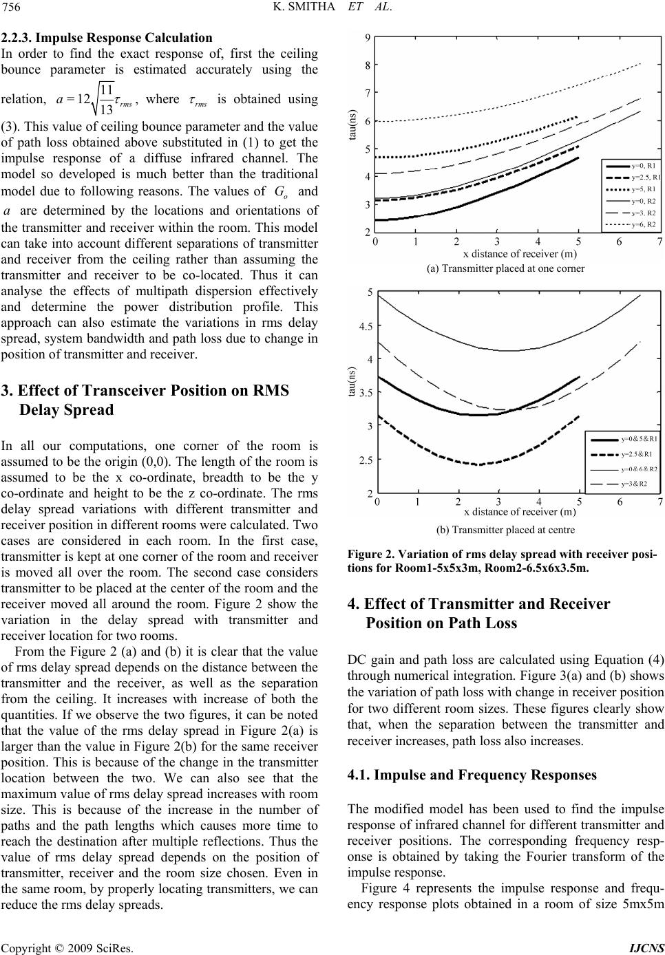 K. SMITHA ET AL. 756 2.2.3. Impulse Response Calculation In order to find the exact response of, first the ceiling bounce parameter is estimated accurately using the relation, 11 =12 13 rms a , where rms is obtained using (3). This value of ceiling bounce parameter and the value of path loss obtained above substituted in (1) to get the impulse response of a diffuse infrared channel. The model so developed is much better than the traditional model due to following reasons. The values of and are determined by the locations and orientations of the transmitter and receiver within the room. This model can take into account different separations of transmitter and receiver from the ceiling rather than assuming the transmitter and receiver to be co-located. Thus it can analyse the effects of multipath dispersion effectively and determine the power distribution profile. This approach can also estimate the variations in rms delay spread, system bandwidth and path loss due to change in position of transmitter and receiver. o G a 3. Effect of Transceiver Position on RMS Delay Spread In all our computations, one corner of the room is assumed to be the origin (0,0). The length of the room is assumed to be the x co-ordinate, breadth to be the y co-ordinate and height to be the z co-ordinate. The rms delay spread variations with different transmitter and receiver position in different rooms were calculated. Two cases are considered in each room. In the first case, transmitter is kept at one corner of the room and receiver is moved all over the room. The second case considers transmitter to be placed at the center of the room and the receiver moved all around the room. Figure 2 show the variation in the delay spread with transmitter and receiver location for two rooms. From the Figure 2 (a) and (b) it is clear that the value of rms delay spread depends on the distance between the transmitter and the receiver, as well as the separation from the ceiling. It increases with increase of both the quantities. If we observe the two figures, it can be noted that the value of the rms delay spread in Figure 2(a) is larger than the value in Figure 2(b) for the same receiver position. This is because of the change in the transmitter location between the two. We can also see that the maximum value of rms delay spread increases with room size. This is because of the increase in the number of paths and the path lengths which causes more time to reach the destination after multiple reflections. Thus the value of rms delay spread depends on the position of transmitter, receiver and the room size chosen. Even in the same room, by properly locating transmitters, we can reduce the rms delay spreads. (a) Transmitter placed at one corner (b) Transmitter placed at centre Figure 2. Variation of rms delay spread with receiver posi- tions for Room1-5x5x3m, Room2-6.5x6x3.5m. 4. Effect of Transmitter and Receiver Position on Path Loss DC gain and path loss are calculated using Equation (4) through numerical integration. Figure 3(a) and (b) shows the variation of path loss with change in receiver position for two different room sizes. These figures clearly show that, when the separation between the transmitter and receiver increases, path loss also increases. 4.1. Impulse and Frequency Responses The modified model has been used to find the impulse response of infrared channel for different transmitter and receiver positions. The corresponding frequency resp- onse is obtained by taking the Fourier transform of the impulse response. Figure 4 represents the impulse response and frequ- ency response plots obtained in a room of size 5mx5m Copyright © 2009 SciRes. IJCNS 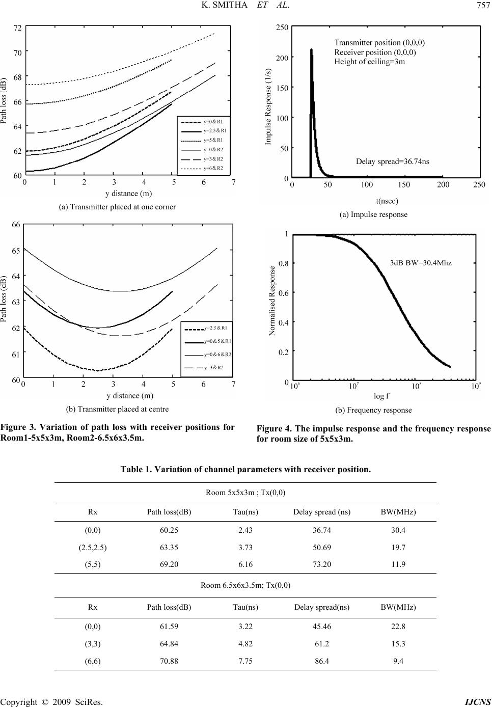 K. SMITHA ET AL. Copyright © 2009 SciRes. IJCNS 757 (a) Transmitter placed at one corner (a) Impulse response (b) Transmitter placed at centre (b) Frequency response Figure 3. Variation of path loss with receiver positions for Room1-5x5x3m, Room2-6.5x6x3.5m. Figure 4. The impulse response and the frequency response for room size of 5x5x3m. Table 1. Variation of channel parameters with receiver position. Room 5x5x3m ; Tx(0,0) Rx Path loss(dB) Tau(ns) Delay spread (ns) BW(MHz) (0,0) 60.25 2.43 36.74 30.4 (2.5,2.5) 63.35 3.73 50.69 19.7 (5,5) 69.20 6.16 73.20 11.9 Room 6.5x6x3.5m; Tx(0,0) Rx Path loss(dB) Tau(ns) Delay spread(ns) BW(MHz) (0,0) 61.59 3.22 45.46 22.8 (3,3) 64.84 4.82 61.2 15.3 (6,6) 70.88 7.75 86.4 9.4  K. SMITHA ET AL. Copyright © 2009 SciRes. IJCNS 758 x3m. Table 1 shows all the important channel parameters obtained using the modified ceiling bounce approach in two rooms of size 5x5x3m and 6.5x6x3.5m. As the separation between the transmitter and receiver increases, the system bandwidth also decreases as is evident from the Table 1. This has effect on the maximum bit rate achievable. With distance the multipath effects are more pronounced, which causes a decrease in the bandwidth, thus resulting in reduction of the maximum bit rate achievable. 5. Conclusions Modified ceiling bounce method to find the propagation properties of the channel is propossed. This method allows computing impulse response of the diffuse channel with less computational complexity than the simple Ceiling bounce model. The influence of transceiver position on the indoor diffuse channel parameters is analyzed. Results clearly show that path loss is a function of separation between the transmitter and receiver. 6. References [1] F. R. Gfeller, and U. Bapst, “Wireless in-house data communication via diffuse infrared radiation,” Pro- ceedings of IEEE., Vol. 67, pp. 1474–1485, 1979. [2] F. R. Gfeller, H. R. Muller, and P. Vettiger, “Infrared communication for in-house applications,” Proceedings of IEEE Conference on Computer Communication, pp. 132–138, 1978. [3] Z. Ghassemlooy and A. C. Boucouvalas, “Guest editorial: Indoor optical wireless communications system and net- works,” International Journal Communication System, Vol. 18, pp. 191–193, 2005. [4] J. R. Barry, J. M. Kahn, W. J. Krause, E. A. Lee, and D. G. Messerschmitt, “Simulation of multipath impulse response for wireless optical channels,” IEEE Journal of Selected Areas on Communication, Vol. 11, pp. 367–379, April 1993. [5] J. R. Barry, “Wireless infrared communication,” Boston: Kluwer, 1994. [6] J. M. Kahn and J. R. Barry, “Wireless infrared commu- nications,” Proceedings of IEEE, Vol. 85, pp. 265–298, February 1997 [7] J. M. Kahn, W. J. Krause, and J. B. Carruthers, “Experimental characterization of nondirected indoor infrared channels,” IEEE Transaction Communication, Vol. 43, pp. 1613–1623, 1995. [8] R. P. Jimenez, J. Berges, and M. J. Betancor, “Statistical model for the impulse response of infrared indoor diffuse channels,” IEE Electronic Letters, Vol. 33, pp. 1298– 1300, 1997. [9] R. P. Jimenez, V. M. Melian, and M. J. Betancor, “Analysis of multipath impulse response of diffuse and quasi-diffuse optical links for IR-WLAN,” Proceedings of 14th Conference on IEEE Computer Communication Society, Vol. 1, pp. 924–930, 1995. [10] J. B. Carruthers and J. M. Kahn, “Modelling of non- directed wireless infrared channels,” IEEE Transa- ction on Communication, Vol. 45, pp. 1260–1268, 1997. |