Advances in Chemical Engi neering and Science , 2011, 1, 198-207
doi:10.4236/aces.2011.14029 Published Online October 2011 (http://www.SciRP.org/journal/aces)
Copyright © 2011 SciRes. ACES
Quasi-Dimensional Modeling of a CNG Fueled HCCI
Engine Combustion Using Detailed Chemical Kinetic
Younes Bakhshan, Amirhossein Shadaei, Saeid Niazi
Department of Mechanical Engineering, University of Hormozgan, Bandar Abbas, Iran
E-mail: Ybakhshan@yahoo.com, A.H.Shadaei@yahoo.com
Recieved August 23, 2011; revised September 15, 2011; accepted October 22, 2011
Abstract
In this study, an in-house quasi dimensional code has been developed which simulates the intake, compres-
sion, combustion, expansion and exhaust strokes of a homogeneous charge compression ignition (HCCI) en-
gine. The compressed natural gas (CNG) has been used as fuel. A detailed chemical kineticscheme consti-
tuting of 310 and 1701 elementary equations developed by [Bakhshan and al.] has been applied for combus-
tion modeling andheat release calculations. The zero-dimensional k-ε turbulence model has been used for
calculation of heat transfer. The output results are the performance and pollutants emission and combustion
characteristics in HCCI engines. Parametric studies have been conducted to discussing the effects of various
parameters on performance and pollutants emission of these engines.
Keywords: HCCI, Quasi Dimensional, Detailed Chemical Kinetic, CNG, Simulation, k-ε
1. Introduction
Homogeneous Charge Compression Ignition (HCCI)
engines are considered to be a new generation of internal
combustion engines that operate on the basis of auto-
ignition and provide a higher thermal efficiency and
lower exhaust pollutants compared to the present classic
versions and is perceived as an engine for future power-
trains which will provide improved fuel efficiency and
lower emissions at the same time and was identified as a
distinct combustion phenomenon about 20 years ago. In
HCCI mode, a mixture of air and fuel is compressed, by
increasing the gas temperature and pressure so, the auto
ignition of the fuel occurs. The advantage of this process
is that the combustion occurs simultaneously in the entire
combustion chamber under lean conditions. The maxi-
mum combustion temperatures are thus reduced to levels
below the NOx formation threshold. Due to the nearly
homogeneous and lean mixture, soot forming fuel-rich
combustion is also avoided. Application of advanced
combustion technologies for optimization of combustion
systems is increasing due to limitation of fossil fuel re-
sources. Initial papers [1,2] recognized the basic charac-
teristics of HCCI that have been validated many times
and in this engine HCCI ignition occurs at many points
simultaneously, with no flame propagation and combus-
tion was described as very smooth with very low cyclic
variation. Noguchi et al. [2] conducted a spectroscopic
study of HCCI combustion and manyradicals were ob-
served, and they were shown to appear in a specific se-
quence. In contrast, with spark-ignited (SI) combustion
all radicals appear at the same time, spatially distributed
through the flame front. These initial HCCI experiments
were done in 2-stroke engines with low compression
ratio and very high EGR.Najt and Foster [3] were first to
run a four-stroke engine in HCCI mode and they also
analyzed the process, considering that HCCI is con-
trolled by chemical kinetics, with negligible influence of
physical effects (turbulencemixing).They used a simpli-
fied chemical kinetics model to predict heat release as a
function of pressure, temperature, and species concentra-
tions in the cylinder.Unfortunately, HCCI has several
problems that have limited its commercialization spe-
cifically, it is very difficult to control the initiation and
rate of combustion over the required speed and load
range of that engine [4]. This is important at higher loads
where very rapid pressure rise and knock are limiting.
HCCI engines also operate at lower combustion tem-
peratures, so more unburned hydrocarbons (UHC) and
CO emissions are generated than in traditional engines
and some of these disadvantages may be reduced or
eliminated by operating these engines in “hybrid mode”,
Y. BAKHSHAN ET AL.
199
where the engine operates in HCCI mode at low power
and in spark-ignited mode [5], or diesel mode [6], at high
power. This hybrid mode takes advantage of high effi-
ciency and low NOx and particulate matter emissions of
HCCI engines at low power conditions. Engine design is
a time consuming process in which many costly experi-
mental tests are normally conducted, and the expense of
optimizing engine designs is even more costly. With in-
creasing prediction ability of engine simulation tools,
engine design aided by relatively low cost CFD model-
ing is becoming more popular in both industry and aca-
demia. In an effort to include the best representation of
both fluid flow and chemical kinetics, attempts have
been made to use three-dimensional CFD models cou-
pled directly with chemical kinetics to study compression
ignition under HCCI like-conditions. Agarwal and As-
sanis [7] reported on the coupling of a detailed chemical
kinetic mechanism for natural gas ignition (22 species
and 104 elementary reactions) with the multi-dimen-
sional reacting flow code and explored the auto-ignition
of natural gas injected in a quiescent chamber under die-
sel like conditions. Kong et al. [8] proposed a similar
approach up to the point of ignition, while after ignition
they introduced a reaction rate incorporating the effects
of both chemical kinetics and turbulent mixing through
characteristic timescales. Hong et al. [9] proposed a
more computationally demanding model to simultane-
ously account for the effects of detailed chemistry and
mixing on ignition delay within the KIVA-3V CFD code.
In this study, an in-house quasi dimensional code has
been developed which simulates the processes occurred
in a HCCI engine fueled with CNG. A detailed chemical
kinetic scheme developed by Bakhshan and Shahrir [12]
constituting of 1701 elementary reactions and 310 spe-
cies and with its modifying toCHEMKIN format, has
been used. Also chemical kinetic scheme used here, in-
volves the reactions required for calculation of NOx. The
zero-dimensional k-ε, turbulence model developed by
Bakhshan and Mansouri [10] has been modified and ap-
plied for calculation of effective velocity and heat trans-
fer from HCCI engine.
2. Model Formulation
2.1. Conservation of Mass
The rate of changeof mass within any open system is the
net flux of massacross the system boundaries.
d
d
j
j
mm
t
(1)
where the subscript “j” refers to each of the component
species present in the mixture and {m} denotes the total
mass within the control cylinder.
2.2. Conservation of Species
The species equations are deduced from their multi- di-
mensional counterparts by neglecting speciesdiffusion-
terms, consistent with the zero-dimensional assumption,
and we have:





jjcyl
M
W
iii
mW
yyy
m
(2)
2.3. Conservation of Energy
From the general energy equation for an open thermo-
dynamic system, with a assumption a single phase,
multi-component mixture of ideal gases, and ideal gas
low,


ii
Ry mTV
PP RmTV
(3)

1
1

 



i
ii
jj
Pv Rm
Th yB
A
Rm
mhPV Q
m
(4)
where 
P
Pv
AC T and . BhPv
2.4. Reactions Formulation
Since detailed chemical kinetics will be used to simulate
the fuel oxidation,A detailed chemical kinetic scheme
developed by Bakhshan and Shahrir [12] constituting of
1701 elementary reactions and 310 species and modified
it to CHEMKIN format has been coupled to our devel-
oped code to calculating the species concentrations during
simulation. The formulations of chemical kinetics are as
blow:
11


KK
ki kki k
kk

ii
(5)
1
I
kk
i
q

(6)
where
 
kiki ki

(7)
 
111










ki ki
KK
K
ikikfikrik
kkk
qaXkXkX

(8)
Copyright © 2011 SciRes. ACES
200
Y. BAKHSHAN ET AL.

1
K
k
k
M
X (9)
e
u
E
RT
b
kAT (10)
2.5. Thermodynamic Properties Treatment
The thermodynamic property treatment will employ the
NASA curve-fits for specific heat, enthalpy, and entropy,
51
1
n
Pk
nk
n
CaT
R
(11)
5,16
1
1
 
nk n
kk
kk
n
kk
a
ha
aT
RTn T
(12)

41,
17
1
ln

nkn
k
kk k
n
a
saT Ta
Rn
k
(13)
The parameters used in above equations are discussed
in nomenclature.
2.6. Heat Transfer Model
The zero-dimensionalk-ε turbulence model given by
bakhshan et al. [10] is used for calculating the charac-
teristics velocity and heat ransfer and the detail of
formulation can be found in refrences [10,11].
2
1
2
K
mU (14)
3
2
kmu
(15)
2
d1
d2
e
ii
e
m
KmV K
tm

(16)
d
d
e
m
kmk
tm
 
(17)

32
323
ukm
(18)
2
3

kP
(19)

24
V
LB
(20)
12
0.3307 
 

B
Kk
cLm (21)
The chimical kineticscheme use here, consist of 1701
elementary reactions and 310 species and the reactions
required for calculation of Nox from extended Zeldovich
mechanism. The general algorithm of code is shown in
Figure 1.
Figure 1. Code flowchart.
3. Results and Discussions
The engine specifications and operation conditionsused
in this simulation and operating conditions for base
engine,are shown in Tables 1 and 2. The fuel considered
here is compound of methane, buthane, propane and
other gases according to Table 2.
The calculation was carried out throughout a thermo-
dynamic cycle and for validation of simulation results,
Table 1. Engine specifications.
EngineFeature Specification
Bore 12.065 cm
Stroke 14 cm
Connecting Rod Length 160 mm
Compression Ratio 19.8
Intake Valve Open 5˚ ATDC
Intake Valve Close 13˚ ABDC
Exhaust Valve Open 39˚ BBDC
Exhaust Valve Close 10˚ BTDC
Table 2. Operating conditions for base engine.
Intake Manifold Pressure (absolute) 1 atm
Intake Manifold Temperature 130˚C
Initial Wall Temperature 130˚C
Equivalence Ratio 0.3
Engine Speed (RPM) 1000
Fuel
CH4 87.15%
C2H6 6.93%
C3H8 3.11%
C4H10 0.63%
IC4H10 0.44%
NC5H12 0.23%
N2 0.32%
CO2 1.19%
Copyright © 2011 SciRes. ACES
Y. BAKHSHAN ET AL.
201
the computed in-cylinder pressure has been compared
with experimental data and are shown in Figures 2 and 3.
The comparison shows good agreement between the si-
mulation results and experimental data and this means,
the constructed model and the coupled detailed chemical
kinetic scheme have good accuracy and can be used as a
tool in calculation of other paparameters in continuation.
After validation of constructed code, the results have
been extracted for a base engine which has capability to
change to HCCI engine. Figures 4 and 5 show the pres-
sure and temperature variation during a thermodynamic
cycle and contains the all processes occurred in internal
combustion engine. (Intake, compression, combustion,
expansion & exhaust). The operating conditions have
been chosento onset the combustion in the cylinder and
this is shown in Figures 4 and 5, because in HCCI en-
gine there is not spark and combustion is started with
chemical kinetic so, the rapid increasing of pressure and
temperature shows the starting of combustion.The heat
transfer has been modelledwith using the zero-dimen-
sional K-εturbulence modeled suggested by Bakhshan et
al. [10]. It has good capability with HCCI engine oper-
ating condition because constants in the model can be
modified to adjust the experimental data with calculation
results, however the variation of heat transfer rate with
crank angle is shown in Figure 6. The heat transfer in-
creases in the compression stroke due to increasing the
velocity of in-cylinder fluid and its rate has the highest
value at this stroke. Also the rate of heat transfer has a
mini-peak value in exhaust stroke, because when the
exhaust valve opens, due to highpressure difference be-
tween inlet and outlet of cylinder, the velocity of the
products at inlet of cylinder increases and thus the heat
transfer rate takes high values.
Figure 7 shows the variation of the components of the
fuel with crank angle.The fuel,especially CH4 increases
in the intake stroke. The sudden decrease of methane and
other components of the fuel mass indicate the onset of
combustion and the auto-ignition point and this shows
that point can be used as a criterion to detect the
auto-ignition and starting the combustion. The major
pollutants produced in the cylinder due to oxidation of
fuel are shown in Figures 8-10. The variations of all
species have good consistency with chemicalkinetic
scheme implemented in modeling in overall. It was
found that the CO value increased rapidly at the start of
combustion, but after the combustion completion, the
oxidation of CO had taken more speed and its concentra-
tion would therefore decrease. Also the CO2 concentra-
tion will increase through oxidation of CO.
The nitrogen oxides (NOx) are important pollutants in
internal combustion engines and the variation of nitrogen
oxides (NOx) are shown in Figure 10. The NO concen-
Figure 2. Comparison of the simulated and measured cyl-
inder pressure.
Figure 3. Comparison of measured and predicted cylinder
pressure during gas exchange processes.
Figure 4. Pressure variation throughout a thermodynamic
cycle with crank angle.
Copyright © 2011 SciRes. ACES
202 Y. BAKHSHAN ET AL.
Figure 5. Temperature variation throughout a thermody-
nam ic cycle with crank angle.
Figure 6. Heat transfer rate variation with crank angle.
Figure 7. Components of the fuelmass variation with crank
angle.
Figure 8. In-cylinder important produced species with crank
angle.
Figure 9. The variation of CO and CO2 with crank angle.
Figure 10. Concentration of NO, N2O & NO with crank
angle.
Copyright © 2011 SciRes. ACES
Y. BAKHSHAN ET AL.
203
tration increases rapidly with starting of combustion due
to increasing the temperature and its value freeze after
taking the maximum value, so this is compatible with
extended Zeldovich mechanism applied in this modelling
which considers only thermal formation of NO. Also the
N2O and NO species have good prediction as shown in
Figure 10.
Several parametric studies of initial temperature, pre-
ssure, equivalence ratio, compression ratio and exhaust
gas recirculation (EGR) were carried out using the com-
plete cycle simulation and these studies are shown
graphically in Figures 11-25. The equivalence ratio is an
important operating parameter and has more effects on
performance and pollutants emission in internal combus-
tion engines. The effects of this parameter on perform-
ance and pollutants variation are shown in Figures 11-13.
With increasing the equivalence ratio, the pressure and
temperature dependent pollutants such as NO increas-
esandat the stoichiometric point, the concentration of NO
take the maximum values due to higher combustion
temperature at this condition. When the mixture is richer,
the concentration of oxygen decreases, while the maxi-
mum temperatureas well as the concentrations of NOx
will decrease, whereas, with leaner mixture, the maxi-
mum temperature decreases. Withincreasing temperature
and pressure at the start of compression stroke, the pres-
sure and temperature of in-cylinder will increase and
starting of combustion shifts to earlier and this is because
the increasing of temperature will start the chemical re-
actions and onset of combustion finally. Also with high
value of initial pressure and temperature NOx increases
due to increasing the maximum in-cylinder temperature.
The effect of intake charge temperature and pressure
on performance and pollutants emission are shown in
Figures 14-19. With increasing the intake charge tem-
perature, the peak in-cylinder temperature will take
higher values but it must be notified that the fuel mass
and total heat released are constant for all intake tem-
perature and the density and volumetric efficiency will
decrease, but the effect of it is less. The intake tempera-
ture effect on pollutants is shown in Figure 16 , and with
increasing the intake temperature, the maximum value of
temperature and so the pollutants are increased. The
pressure effectsare similar with temperature and are
shown in Figures 17-19. With increasing the intake
charge pressure, the in-cylinder temperature, in-cylinder
pressure and dependent pollutants are increased.
Another important operating parameter for internal
combustion engines at optimum working is the exhaust
gas recirculation (EGR) which is used for control of
pollutants emission. EGR involves the gases from
cylinder combustion products such as CO2, CO, NO,
H2O, and so on. These gases have important role in
Figure 11. Effect of equivalence ratio on ignition and pres-
sure.
Figure 12. Effect of equivalence ratio on in-cylinder tem-
perature.
Figure 13. Effect of equivalence ratio on major pollutants
variation.
Copyright © 2011 SciRes. ACES
204 Y. BAKHSHAN ET AL.
Figure 14. Effect of intake charge temperature on ignition.
Figure 15. Variation of in-cylinder temperature with crank
angle at different intake temperatures.
Figure 16. Variation of pollutants emission with intake
temperature.
Figure 17. Effect of intake charge pressure on ignition.
Figure 18. Effect of intake charge pressure on in-cylinder
temperature.
Figure 19. Effect of intake charge pressure on pollutants.
Copyright © 2011 SciRes. ACES
Y. BAKHSHAN ET AL.
205
changing the specific heat capacity of intake charge
mixture and thus for control of initial temperature and
pressure of cylinder. The effects of EGR on performance
and pollutants of hcci engine are shown in Figures 20-22.
Increasing the exhaust gas recirculation (EGR) value, will
cause the shift of onset of combustion to earlier due to
increasing the temperature, but the effect of EGR on
temperature and pressure increasing, is less than the other
parameters because, with increasing the EGR, the total
molecular weight of mixture will increase and this results
the increasing of heat capacity of mixture. Also with
increasing the EGR value near to optimum value, will
result the decreasing of NO and CO. It must be notified
that the operation of engine with non-optimum value
Figure 20. Pressure variation with crank angle at different
EGR values.
Figure 21. Temperaurevariation with crank angle at dif-
ferent EGR values.
Figure 22. Effect of EGR on pollutants.
of EGR will result the increasing of major pollutants.
The compression ratio (CR) parameter is using for
control of onset of knock in internal combustion engines
and it is an important parameter in designing of an internal
combustion engine. Also, it is a key parameter in in-
creasing the engine efficiency but it’s value is limited by
knock phenomena. The effects of compression ratio on
performance and pollutants are shown in Figures 23-25.
With increasingthe CR, the pressure and temperature
increases and the onset of combustion (starting of
chemical reaction) will shifts to earlier on crank angle axis,
also with increasing the CR, NOx pollutants increase due
to temperature increasing but the CO emission change
very slowly.
Figure 23. Pressure variation with crank angle at different
compression ratio.
Copyright © 2011 SciRes. ACES
206 Y. BAKHSHAN ET AL.
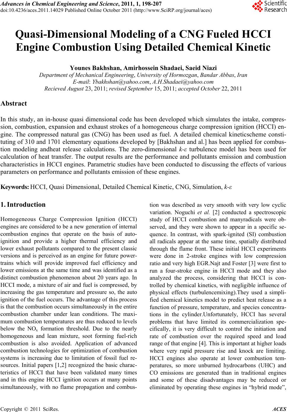
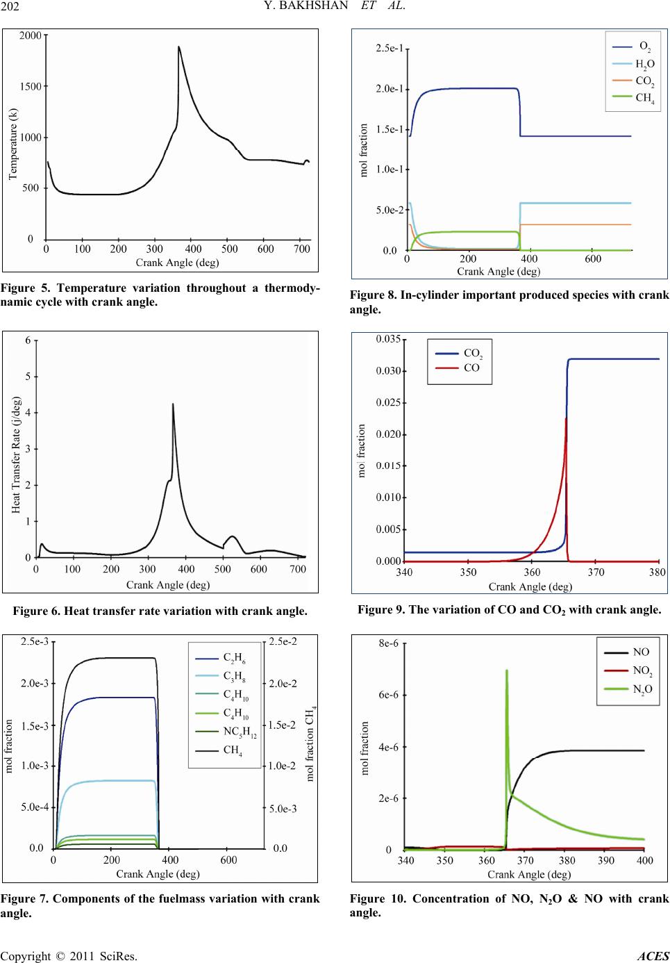
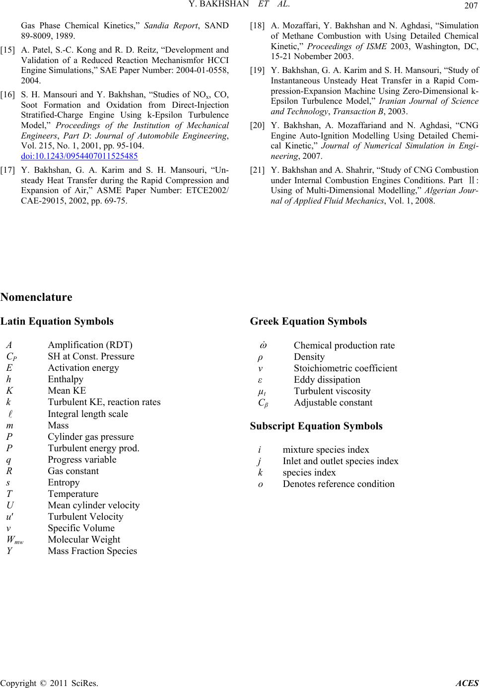
Figure 24. Temperature variation with crank angle at dif-
ferent compression ratio .
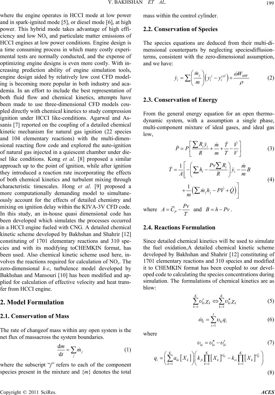
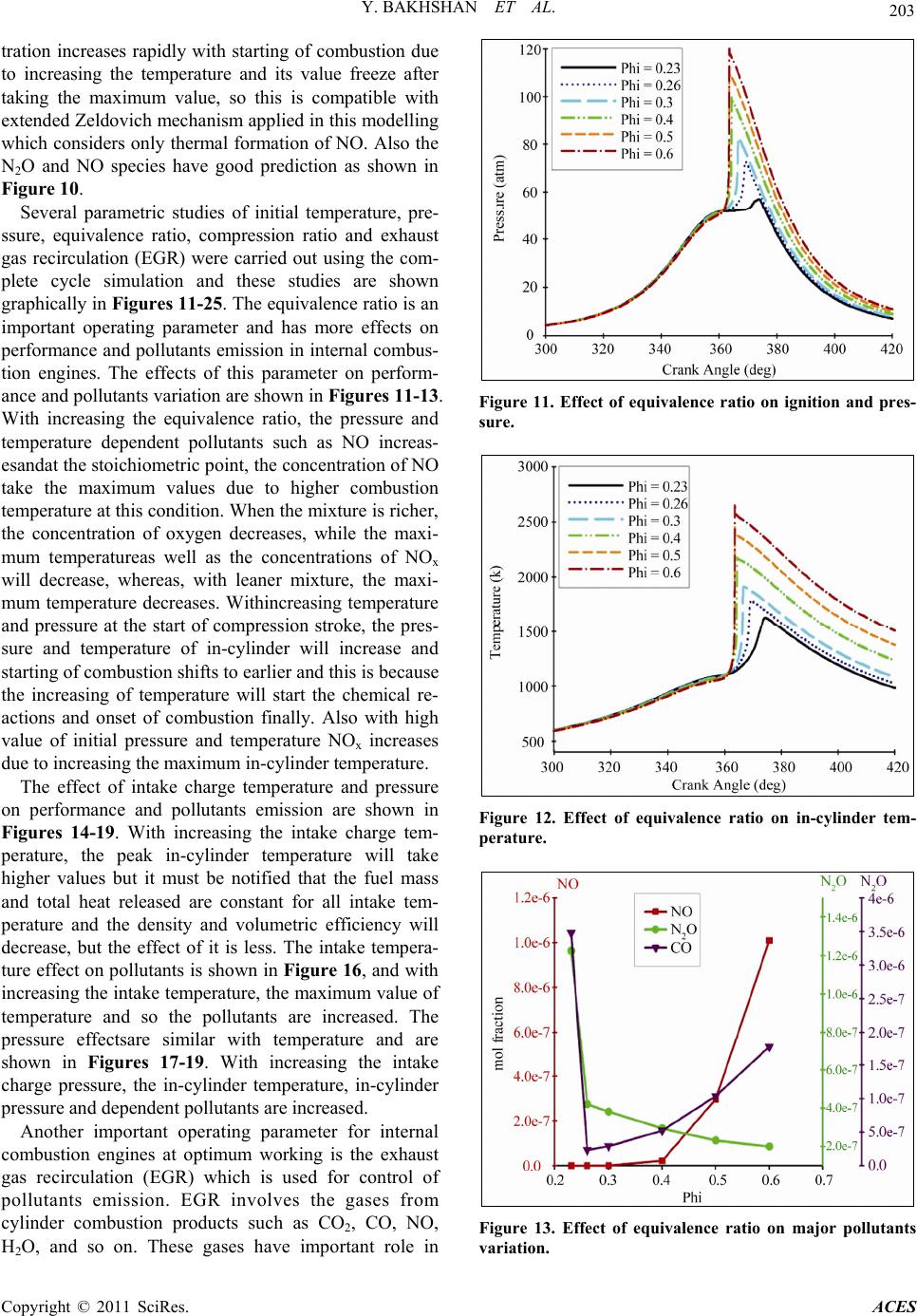
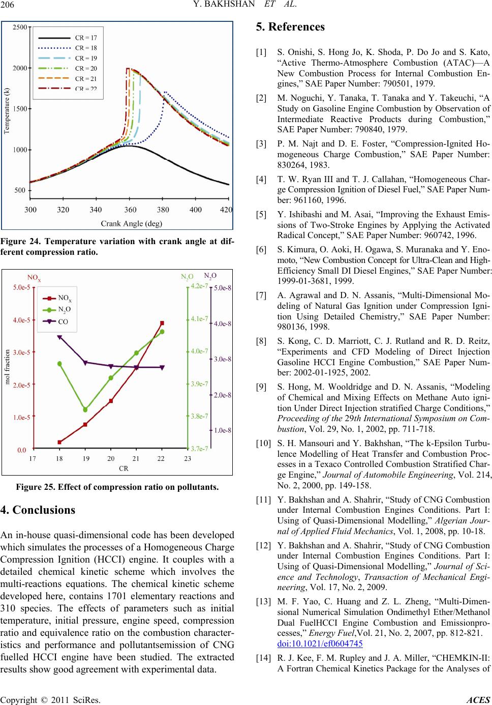
Figure 25. Effect of compression ratio on pollutants.
4. Conclusions
An in-house quasi-dimensional code has been developed
which simulates the processes of a Homogeneous Charge
Compression Ignition (HCCI) engine. It couples with a
detailed chemical kinetic scheme which involves the
multi-reactions equations. The chemical kinetic scheme
developed here, contains 1701 elementary reactions and
310 species. The effects of parameters such as initial
temperature, initial pressure, engine speed, compression
ratio and equivalence ratio on the combustion character-
istics and performance and pollutantsemission of CNG
fuelled HCCI engine have been studied. The extracted
results show good agreement with experimental data.
5. References
[1] S. Onishi, S. Hong Jo, K. Shoda, P. Do Jo and S. Kato,
“Active Thermo-Atmosphere Combustion (ATAC)—A
New Combustion Process for Internal Combustion En-
gines,” SAE Paper Number: 790501, 1979.
[2] M. Noguchi, Y. Tanaka, T. Tanaka and Y. Takeuchi, “A
Study on Gasoline Engine Combustion by Observation of
Intermediate Reactive Products during Combustion,”
SAE Paper Number: 790840, 1979.
[3] P. M. Najt and D. E. Foster, “Compression-Ignited Ho-
mogeneous Charge Combustion,” SAE Paper Number:
830264, 1983.
[4] T. W. Ryan III and T. J. Callahan, “Homogeneous Char-
ge Compression Ignition of Diesel Fuel,” SAE Paper Num-
ber: 961160, 1996.
[5] Y. Ishibashi and M. Asai, “Improving the Exhaust Emis-
sions of Two-Stroke Engines by Applying the Activated
Radical Concept,” SAE Paper Number: 960742, 1996.
[6] S. Kimura, O. Aoki, H. Ogawa, S. Muranaka and Y. Eno-
moto, “New Combustion Concept for Ultra-Clean and High-
Efficiency Small DI Diesel Engines,” SAE Paper Number:
1999-01-3681, 1999.
[7] A. Agrawal and D. N. Assanis, “Multi- Dimensional Mo-
deling of Natural Gas Ignition under Compression Igni-
tion Using Detailed Chemistry,” SAE Paper Number:
980136, 1998.
[8] S. Kong, C. D. Marriott, C. J. Rutland and R. D. Reitz,
“Experiments and CFD Modeling of Direct Injection
Gasoline HCCI Engine Combustion,” SAE Paper Num-
ber: 2002-01-1925, 2002.
[9] S. Hong, M. Wooldridge and D. N. Assanis, “Modeling
of Chemical and Mixing Effects on Methane Auto igni-
tion Under Direct Injection stratified Charge Conditions,”
Proceeding of the 29th International Symposium on Com-
bustion, Vol. 29, No. 1, 2002, pp. 711-718.
[10] S. H. Mansouri and Y. Bakhshan, “The k-Epsilon Turbu-
lence Modelling of Heat Transfer and Combustion Proc-
esses in a Texaco Controlled Combustion Stratified Char-
ge Engine,” Journal of Automobile Engineering, Vol. 214,
No. 2, 2000, pp. 149-158.
[11] Y. Bakhshan and A. Shahrir, “Study of CNG Combustion
under Internal Combustion Engines Conditions. Part I:
Using of Quasi-Dimensional Modelling,” Algerian Jour-
nal of Applied Fluid Mechanics, Vol. 1, 2008, pp. 10-18.
[12] Y. Bakhshan and A. Shahrir, “Study of CNG Combustion
under Internal Combustion Engines Conditions. Part I:
Using of Quasi-Dimensional Modelling,” Journal of Sci-
ence and Technology, Transaction of Mechanical Engi-
neering, Vol. 17, No. 2, 2009.
[13] M. F. Yao, C. Huang and Z. L. Zheng, “Multi-Dimen-
sional Numerical Simulation Ondimethyl Ether/Methanol
Dual FuelHCCI Engine Combustion and Emissionpro-
cesses,” Energy Fuel,Vol. 21, No. 2, 2007, pp. 812-821.
doi:10.1021/ef0604745
[14] R. J. Kee, F. M. Rupley and J. A. Miller, “CHEMKIN-II:
A Fortran Chemical Kinetics Package for the Analyses of
Copyright © 2011 SciRes. ACES
Y. BAKHSHAN ET AL.
Copyright © 2011 SciRes. ACES
207
Gas Phase Chemical Kinetics,” Sandia Report, SAND
89-8009, 1989.
[18] A. Mozaffari, Y. Bakhshan and N. Aghdasi, “Simulation
of Methane Combustion with Using Detailed Chemical
Kinetic,” Proceedings of ISME 2003, Washington, DC,
15-21 Nobember 2003.
[15] A. Patel, S.-C. Kong and R. D. Reitz, “Development and
Validation of a Reduced Reaction Mechanismfor HCCI
Engine Simulations,” SAE Paper Number: 2004-01-0558,
2004.
[19] Y. Bakhshan, G. A. Karim and S. H. Mansouri, “Study of
Instantaneous Unsteady Heat Transfer in a Rapid Com-
pression-Expansion Machine Using Zero-Dimensional k-
Epsilon Turbulence Model,” Iranian Journal of Science
and Technology, Transaction B, 2003.
[16] S. H. Mansouri and Y. Bakhshan, “Studies of NOx, CO,
Soot Formation and Oxidation from Direct-Injection
Stratified-Charge Engine Using k-Epsilon Turbulence
Model,” Proceedings of the Institution of Mechanical
Engineers, Part D: Journal of Automobile Engineering,
Vol. 215, No. 1, 2001, pp. 95-104.
doi:10.1243/0954407011525485
[20] Y. Bakhshan, A. Mozaffariand and N. Aghdasi, “CNG
Engine Auto-Ignition Modelling Using Detailed Chemi-
cal Kinetic,” Journal of Numerical Simulation in Engi-
neering, 2007.
[17] Y. Bakhshan, G. A. Karim and S. H. Mansouri, “Un-
steady Heat Transfer during the Rapid Compression and
Expansion of Air,” ASME Paper Number: ETCE2002/
CAE-29015, 2002, pp. 69-75.
[21] Y. Bakhshan and A. Shahrir, “Study of CNG Combustion
under Internal Combustion Engines Conditions. Part :
Using of Multi-Dimensional Modelling,” Algerian Jour-
nal of Applied Fluid Mechanics, Vol. 1, 2008.
Nomenclature
Latin Equation Symbols Greek Equation Symbols
Chemical production rate
ρ Density
ν Stoichiometric coefficient
ε Eddy dissipation
µt Turbulent viscosity
Cβ Adjustable constant
A Amplification (RDT)
CP SH at Const. Pressure
E Activation energy
h Enthalpy
K Mean KE
k Turbulent KE, reaction rates
Integral length scale
m Mass
P Cylinder gas pressure
P Turbulent energy prod.
q Progress variable
R Gas constant
s Entropy
T Temperature
U Mean cylinder velocity
u Turbulent Velocity
v Specific Volume
Wmw Molecular Weight
Y Mass Fraction Species
Subscript Equation Symbols
i mixture species index
j Inlet and outlet species index
k species index
ο Denotes reference condition