Advances in Chemical Engi neering and Science , 2011, 1, 169-175
doi:10.4236/aces.2011.14025 Published Online October 2011 (http://www.SciRP.org/journal/aces)
Copyright © 2011 SciRes. ACES
Structured Perovskite-Based Oxides: Use in the Combined
Methane Reforming
Adriana García1, Norymar Becerra1, Luis García1, Ini Ojeda1, Estefanía López1,
Carmen M. López2, Mireya R. Goldwasser2
1Facultad de Ingenier í a, Universidad Central de Venezuela, Caracas, Venezuela
2Facultad de Ciencias, Universidad Central de Venezuela, Caracas , Venezuela
E-mail: adriana.ucv@gma il.com
Recieved July 16, 2011; revised August 10, 2011; accepted August 30, 2011
Abstract
The behavior of metallic structured perovskite-based catalysts was evaluated in the combined methane re-
forming reaction with CO2-O2. The reaction conditions were established by varying the reaction temperature
and reactor input composition in the range of 650 to 850˚C and CH4/CO2 ratio 1 to 5, respectively. The re-
sults of the catalytic tests at 750˚C showed a positive effect of the metallic structure, producing higher con-
versions and H2/CO ratios in the products compare to that obtained with the powder catalyst.
Keywords: Methane Reforming, Perovskites, Syngas Production, Structured Catalysts
1. Introduction
Catalytic steam methane reforming (SMR) is the princi-
pal commercial technology for syngas production [1-3].
This process has the advantage of using natural gas as
feedstock, which is an abundant material available at low
cost, in addition to producing a high H2/CO ratio, ac-
cording Equation (1):
422 r
CHHOCO3H(H206 kJ/mol)  (1)
Since this reaction (Equation (1)) is highly endother-
mic, it is necessary to use high temperature and pressures.
These severe reaction conditions cause catalyst deactiva-
tion due to carbon deposits on the catalyst surface. The
possibility of combining exothermic oxidation of meth-
ane (Equations (2) and (3)) with the SMR has emerged
as an alternative to overcome this disadvantage. The pur-
pose is to provide the heat required by the endothermic
reactions, from the heat released by the exothermic reac-
tions [4-6]. In the same way, methane reforming with
carbon dioxide, known as dry methane reforming (DMR),
to produce syngas with a H2/CO ratio equal to unity
(Equation (4)), is one of the methods that utilize one the
major greenhouse contributor. There are abundant re-
serves of natural gas with significant proportions of CO2,
which can serve as raw material to the process of dry
methane reforming. The combination of DMR and dry
methane oxidation (Equations (2) and (3)) is known as
combined methane reforming. Recently this subject has
been a matter of increasing interest as observed by the
large number of publications [7-10].
42 2r
1
C
HOCO 2H(H36 kJ/mol)
2
  (2)
4222 r
CH2OCO 2HO(H802 kJ/mol) (3)
42 2r
CHCO2CO 2H(H264 kJ/mol) (4)
Combination of exothermic and endothermic reactions
is a very important accomplishment to obtain tempera-
ture compensation of the process. A new approach pre-
sented by several authors is based in the use of structured
metal carriers instead of random ceramic supports. The
new carriers with open structures allow achievement of
higher heat transfer coefficients and lower pressures drop
[11-13].
Oxygen addition to DMR reduces carbon deposition
on the catalyst surface and increases methane conversion.
Similarly, the type of catalyst used could also inhibit
coke formation. In this sense, the use of perovskite type
oxides emerge as an alternative since after reduction it is
possible to produce highly disperse metallic particles,
diminishing deactivation of the catalyst by suppressing
the coke forming reactions [14-18]. However, the re-
fractory character of heat conduction in perovskite ox-
ides could be disadvantageous to the combined processes.
The use of metallic structures as carriers of catalysts has
170 A. GARCÍA ET AL.
arisen as a way to achieve a better heat transfer in the
catalytic bed.
In this work, we present the results of combined me-
thane reforming with CO2 and O2, using metallic struc-
tures similar to a commercial packing, as supports for
LaNiO3 perovskite-type oxide. The performance of these
systems is compared to the unsupported catalyst.
2. Experimental
2.1. Catalyst Preparation and Characterization
The studied LaNiO3 perovskite-type oxide was synthe-
sized using a modification of the citrate sol-gel method
[19]. Adequate amounts of the cationic precursors (La
and Ni) were dissolved under vigorous stirring in a solu-
tion of citric acid (Riedel-de Haen) with an equal propor-
tion of ethylene glycol (Riedel-de Haen) as the organic
polydentate ligand. The formed gel was subjected to
evaporation at 80˚C; then the gel was heating to 200˚C at
a rate of 0.5˚C/min. At this temperature a flow of oxygen
was incorporated and the heating was continued to 400˚C
at a rate of 1˚C/min.
Solids were characterized by several techniques such
as X-ray diffraction (XRD) using a Bruker AXS D-8
Advance diffractometer with a Co k radiation, for crys-
talline phase detection between 20˚ and 80˚ 2
. JCPDS-
ICDD standard files software was used to determine the
phases. The IR spectra were recorded in a Nexus FT-IR
470 spectrometer in the range 1200 - 400 cm–1. The sur-
face area was measured by a single-point BET procedure
using nitrogen-argon adsorption at –196˚C with a N2/Ar
ratio of 30/70 on a Micromeritics Model ASAP 2010.
The images of scanning electron microscopy (SEM)
were taken with a Hitachi S-500 microscope, operated at
20 keV and 50 mA. Chemical composition was deter-
mined by electron probe microanalysis on an EDX de-
tector Kevex 7000 System. The temperature programmed
reduction analysis (TPR) was carried out in a Thermo-
Quest TPD/TPR 1100 system using about 50 mg of the
sample in 8 vol% H2/92 vol% Ar stream (20 mL/min).
The temperature was raised from room temperature to
120˚C at a rate of 10˚C/min, then holding it for 15 min to
remove any adsorbed water, and raised again up to
1000˚C for 2 h.
The metal structures were hand manufactured with a
form similar to the commercial packing Mellapak® of
Sulzer (Figure 1(a)) [20], using strips of 316 stainless
steel 100 mesh (Figures 1(b) and 1(c)). These structures
were acid treated by 24 h at room temperature, to pro-
duce a rougher surface and thus improve catalyst adhe-
sion. The incorporation of the perovskite-type oxide to
the metal structure was carried out after evaporation at
80˚C; where the viscosity of the sample allows a better
adherence. The immersion method was used to impreg-
(a) (b) (c)
Figure 1. Metal structures (a) Mellapak packaging; (b)
elaborated disks; (c) cross-section of the elaborated disks.
nate the metal structure with the perovskite-type oxide
[21]. The structured catalyst was examined by scanning
electronic microscopy (SEM).
2.1. Activity Tests
Catalytic tests were carried out in a fixed bed continuous
flow system with a stainless steel reactor. Before the
catalytic tests, the solids were reduced in H2 flow (50
mL/min, T = 800˚C, 8 h). After reduction, the system
was swept with Ar for 30 min and adjusted to reaction
temperature. The reaction was carried out at atmospheric
pressure between 600˚C and 800˚C, 24 Lh–1·g–1 hourly
space velocitie with a molar ratio CH4/O2 = 2 for the
combine reforming [15,22]. The water produced during
reaction was condensed before passing the reactor out-
flow to the analyzing system, which consisted of an
on-line gas chromatograph (Varian 3300) equipped with
a TCD detector and provided with a Carbosieve SII
80/100 column. The CH4 and CO2 conversions are de-
fined as the CH4 and CO2 converted per total amount of
CH4 and CO2 fed, respectively. The total conversion
(%Xi) was calculated according to Equation (5), from the
values of areas (Ai) with nitrogen as a reference com-
pound. The subscripts “s” and “e” refer to the flows in
and out of the reactor, respectively.


i
Ai/Aref s
%X 1*100
Ai/Aref e



(5)


2
H22
2
CO 2
AfH N
H*
COAfCO N
(6)
The H2/CO molar ratio of the reaction products was
determined using Equation (6), with the previously eva-
luated response factors, f.
3. Results and Discussion
3.1. Catalysts Characterization
IR and XRD analyses were performed to verify forma-
tion of the perovskite-type structure. The IR spectra of
Copyright © 2011 SciRes. ACES
A. GARCÍA ET AL.
171
the synthesized solids showed two broad bands charac-
teristics of ABO3 mixed-oxide centered at 420 and 523
cm–1. Their positions are in good agreement with those
reported in the literature [15,18]. The BET specific sur-
face area of the synthesized perovskite, measure after
calcined was 8 m2/g. This value is typical for perovskites
synthesized by the citrate sol-gel method [15]. The XRD
pattern of synthesized perovskite shown in Figure 2,
reveal the presence of crystalline LaNiO3. A notable
change was observed in the XRD pattern of the reduced
perovskite, as shown in Figure 3. After reduction, struc-
tural breakdown of the perovskite occur producing Ni0,
La2O3 and La(OH)3.
The TPR profile of LaNiO3 perovskite-type oxide is
shown in Figure 4. A first hydrogen consumption peak
at ~400˚C, attributed to reduction of Ni4+ species to Ni2+
is observed. The second hydrogen consumption peak
appears at ~500˚C, assigned to reduction of Ni2+ to Ni0,
in agreement with a stepwise reduction.
The chemical composition of stainless steel mesh used
to elaborate the metal structures, was determined by
SEM coupled with EDX. The main components were Fe
(68%) and Cr (19%), followed by Ni (6%), Si (3%), Al
(3%) and Mn (2%).
The SEM micrographs (Figures 5(a) and 5(b)) show-
ed the roughness achieved by the acid treatment per-
formed. Figure 5(c) shows an image of the LaNiO3 pe-
rovskite-type oxide on the structure, and Figure 5(d)
shows an image of the powder perovskite-type oxide. A
morphology that could be described as “flakes” was ob-
served for supported and powder perovskites-type oxides.
The adherence of the powder perovskites-type oxides on
the metal structure was evaluated by immersing it in
ethanol with ultrasonic bath for 15 min, obtaining a 97%
adherence.
Figure 2. XRD pattern of synthesi zed LaNiO3.
Figure 3. XRD pattern of LaNiO3 perovskite-type oxide
after reduct i o n under H2 stream.
Figure 4. TPR profile of LaNiO3 perovskite-type oxide.
(a) (b)
(c) (d)
Figure 5. SEM Images (a) untreated stainless steel mesh
(500×), (b) acid treated stainless steel mesh (500×), (c) pe-
rovskite supported on the mesh (500×), (d) powder LaNiO3
perovskite (800×).
Copyright © 2011 SciRes. ACES
172 A. GARCÍA ET AL.
3.2. Catalytic Tests
The results of catalytic tests of the methane combined
reforming with CO2 and O2 as a function of reaction
temperature are shown in Table 1. The temperature was
varied between 650˚C and 850˚C, with intervals of 50˚C,
using 300 mg of LaNiO3 structured catalyst with
CH4/CO2/O2 molar ratio of 2/1/1. At 650˚C, after a 12 h
induction period, a 67% methane conversion was ob-
tained. At the beginning of the reaction, oxidation of
metallic nickel could occur due to the high affinity be-
tween Ni and O2 [23]; which is then progressively re-
duced by the H2 produced in the reforming reaction, until
stability is reached. 100% oxygen conversion was ob-
tained during the entire tests, due to the fact that oxida-
tion reactions are thermodynamically and kinetically
favored [24]. An increase of methane and CO2 conver-
sion with increasing temperature was obtained, as shown
in Table 2. The consumption of methane by oxidation
and CO2 reactions (Equation (4)) can explain the higher
methane conversion observed compare to CO2 conver-
sion, the last one being favored at temperature above
700˚C, due to its endothermic nature. H2/CO molar ratio
in the reaction products remained around 1.4.
A second experiment at 750˚C was performed varying
the CH4/CO2 molar ratio in the input stream between 1
and 5, as shown in Table 2.
It is observed (Table 2) that the methane conversion
increases with increasing the CH4/CO2 ratio, while a
maximum for the CO2 conversion was attained at a
CH4/CO2 ratio of 4. A higher H2/CO ratio was also ob-
tained for this CH4/CO2 ratio. Carbon formation without
catalyst deactivation was observed during this experience.
The carbon formed is presented as elongated filaments,
as analyzed by SEM (Figure 6(a)), similar to those ob-
served by Rynkowski et al. [25].
Table 1. CH4 and CO2 conversions and on H2/CO ratio as a
function of temperature.
Temperature˚C %
4
CH
X% 2
CO
X H2/CO
650 67 32 1.48
700 68 46 1.39
750 78 55 1.40
800 91 73 1.44
850 97 76 1.41
24 Lh–1·g–1; CH4/CO2 = 1; 300 mg cat.
Table 2. Effect of the CH4/CO2 ratio in the input stream on
CH4 and CO2 conversions and H2/CO ratio.
CH4/CO2 %
4
CH
X% 2
CO
X H2/CO
1 72 40 1.08
2 81 52 1.47
4 89 61 1.92
5 91 52 1.89
24 Lh–1·g–1; 750 ˚C; 300 mg cat.
(a) (b)
Figure 6. SEM Images of the catalysts after reaction: (a)
8000×, (b) 100×.
Figure 5(b) shows an image of the structured catalyst
after reaction; when it is compared to the catalyst before
reaction (Figure 5(c)) it can be observed that the struc-
ture is more opaque and that it has a layer of a denser
solid. The solid layer coating the structure after reaction
can be attributed to formation of lanthanum dioxomono-
carbonate (La2O2CO3), whose characteristic lines were
observed in the XRD pattern of the catalyst after reaction
(Figure 7).
The combined methane reforming with CO2 and O2,
involves a complex set of reactions, where the predomi-
nance of a given reaction depends on the catalyst and
reaction conditions. In addition to the reactions 1 to 4,
the following reactions may occur:
22
COHCOHOWGS reverse (7)
(8)
2
2COCCOBoudouard reaction
42
CHC 2HMethanecracking (9)
Several possibilities have to be considered to analyze
the observed results:
In the case of CH4/CO2 = 1 ratio, the proportion of
CO2 in the input stream to the reactor is higher than the
oxygen proportion (CH4/O2 = 2). However, combustion
reactions occur (Equations (2) and (3)) because they are
kinetic and thermodynamically favored. The reforming
of methane with CO2 (Equation (4)), also is promoted
due to the high temperature and high concentration of
CO2. The reaction conditions also favor the reverse water gas
Figure 7. XRD pattern of after reaction catalysts.
Copyright © 2011 SciRes. ACES
A. GARCÍA ET AL.
173
shift reaction (Equation (7)) and methane cracking
(Equation (9)). Thus if under these conditions, reactions
(2) + (3) + (4) + (7) + (9) are predominant, the overall
reaction can be represented by Equation (10), with a
H2/CO = 1.25 ratio, comparable to the experimental
value obtained.
422 22
4CH5/2OCO 4CO5H3HOC 
(10)
For the CH4/O2 = 2 molar ratio, the value obtained for
the H2/CO ratio in the products suggests the combination
of reactions (3) + (4) + (1) + (7)+ (8) to give the global
reaction represented by Equation (11). The H2/CO = 1.47
ratio obtained is comparable to the H2/CO ratio accord-
ing to the Equation (11).
42 222
4CH2OCO4CO 6H2HO C   (11)
For CH4/CO2 = 4 ratio, the highest H2/CO molar ratio
(1.92) was obtained. Under these conditions the occur-
rence of Reactions (1-4) and (7-8) are favored, giving
rise to the overall reaction represented by Equation (12).
The H2/CO ratio for this Equation is 2, in good agree-
ment with 1.92 obtained experimentally.
42 22
4CH5/2O3CO 6H2HOC  (12)
The CH4/CO2 ratio equal to 4 implies a higher amount
of CH4 compared to CO2. In this case the oxygen propor-
tion is lower than that of CO2, which can favoured oxi-
dation reactions producing a higher proportion of H2O
and CO2. As a consequence, the contribution of Reac-
tions (1) and (4) is stronger, giving raise to a higher
H2/CO ratio in the reaction products. The molar ratio for
4/1/2 CH4/CO2/O2 was selected to compare the perform-
ance of the structured catalyst with respect to the powder
catalyst.
3.3. Structured and Powder Catalytic Tests
Results of the catalytic tests for both structured and
powder catalysts are shown in Figure 8, at 750˚C and
CH4/CO2/O2 molar ratios of 4/1/2. A significant im-
provement in the conversion of CH4 and CO2 over the
structured catalyst was obtained; in addition, the induc-
tion period required by the powder catalyst was not re-
quired on the structured catalyst. During the first 20 h of
time on stream, negative conversion values of CO2 were
obtained, because proportion of CO2 produced from total
combustion (Equation (3)) is higher than the consumed
CO2. On the other hand, H2/CO molar ratio in reaction
products was 1.94; this value is higher than the H2/CO
ratio obtained with the powder catalyst, which was 1.64.
The purpose of the metal structure is to take advantage
of improving heat transfer in the catalytic bed. Thus, the
increase of catalytic activity can be attributed to better
Figure 8. CH4 and CO2 conversions of structured and pow-
der catalysts.
employment by endothermic reactions such as reforming
of methane with CO2 and H2O of the heat released by
exothermic reactions. Moreover, the shape of the struc-
ture could allow a greater contact between the catalyst
and reagents.
The catalytic stability of the structured catalyst was
evaluated during 52 hours on stream. Results are shown
in Figure 9; after 24 hours the catalyst seems to reach
steady-state conditions, the conversion of methane and
CO2 remain in average values of 90 and 60% respec-
tively, and the H2/CO ratio in reaction products was
close to 2. The catalyst stability despite carbon formation
has been attributed to the formation of La2O2CO3 during
the reaction [26], according to XRD pattern of the solid
after reaction such as shown in Figure 7.
4. Conclusions
The LaNiO3 perovskite-type oxide was obtained as a
Figure 9. Catalytic stability test of structured catalyst.
Copyright © 2011 SciRes. ACES
174 A. GARCÍA ET AL.
pure highly crystalline phase, which after reduction pre-
sented major structural changes, giving rise to well dis-
perse nickel metallic particles on a lanthanum oxide and
hydroxide matrix.
An adherence of 97% of the perovskite-type oxide to
the metallic surface was achieved by means of the acid
treatment carried out to the metal structure the immer-
sion procedure used in the preparation of the structured
catalyst.
The system studied is complex and involves several
reactions that depend largely on the composition of the
feed to reactor, as well as of the catalyst and the opera-
tional reaction conditions employed.
A positive influence of the metallic structure in the
combined methane reforming reaction with CO2-O2 was
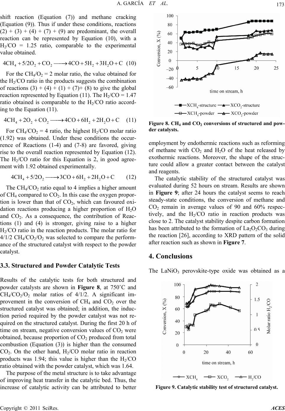
observed. The stability of the structured catalyst was
higher compared to that observed for the powder catalyst.
In addition, no induction period was required for the
structured catalyst.
5. Acknowledgements
The authors are grateful to CDCH UCV for the financial
support through project No 08-00-6607-2006.
6. References
[1] L. Profeti, E. Ticianelli and E. Assaf, “Co/Al2O3 Cata-
lysts Promoted with Noble Metals for Production of Hy-
drogen by Methane Steam Reforming,” Fuel, Vol. 87, No.
10-11, 2008, pp. 2076-2081.
doi:10.1016/j.fuel.2007.10.015
[2] A. Iulianelli, G. Manzolini, S. Campanari, T. Longo, S.
Liguori and A. Basile, “H2 Production by Low Pressure
Methane Steam Reforming in a Pd-Ag Membrane Reac-
tor over a Ni-Based Catalyst: Experimental and Model-
ing,” International Journal of Hydrogen Energy, Vol. 35,
No. 20, 2010, pp. 11514-11524.
[3] X. Song and Z. Guo, “Technologies for Direct Production
of Flexible H2/CO Synthesis Gas,” Energy Conversion
and Management, Vol. 47, No. 5, 2006, pp. 560-569.
doi:10.1016/j.enconman.2005.05.012
[4] G. Wang and M. Coppens, “Rational Design of Hierar-
chically Structured Porous Catalyst for Autothermal Re-
forming of Methane,” Chemical Engineering Science,
Vol. 65, No. 7, 2010, pp. 2344-2351.
doi:10.1016/j.ces.2009.09.079
[5] A. De Souza, L. Lins, N. Filho and C. De Abreu, “Cata-
lytic Activity Evaluation for Hydrogen Production via
Autothermal Reforming of Methane,” Catalysis Today,
Vol. 149, No. 3-4, 2010, pp. 413-417.
doi:10.1016/j.cattod.2009.06.003
[6] W. Chen, M. Lin, J. Lu, Y. Chao and T. Leu, “Thermo-
dynamic Analysis of Hydrogen Production from Methane
via Autothermal Reforming and Partial Oxidation Fol-
lowed by Water Gas Shift Reaction,” International Jour-
nal of Hydrogen Energy, Vol. 35, No. 21, 2010, pp.
11787-11797. doi:10.1016/j.ijhydene.2010.08.126
[7] R. Ganesh, D. Bhaskar and R. Ajit, “Thermodynamic
Study of Combining Chemical Looping Combustion and
Combined Reforming of Propane,” Fuel, Vol. 89, No. 10,
2010, pp. 3141-3146. doi:10.1016/j.fuel.2010.05.029
[8] Q. Jing and X. Zheng, “Combined Catalytic Partial Oxi-
dation and CO2 Reforming of Methane over ZrO2-Modi-
fied Ni/SiO2 Catalysts Using Fluidized-Bed Reactor,”
Energy, Vol. 31, No. 12, 2006, pp. 2184-2192.
doi:10.1016/j.energy.2005.07.005
[9] J. Múnera, C. Carrara, L. Cornaglia and E. Lombardo,
“Combined Oxidation and Reforming of Methane to Pro-
duce Pure H2 in a Membrane Reactor,” Chemical Engi-
neering Journal, Vol. 161, No. 1-2, 2010, pp. 204-211.
doi:10.1016/j.cej.2010.04.022
[10] J. Gao, Z. Hou, X. Liu, Y. Zeng, M. Luo and X. Zheng,
“Methane Autothermal Reforming with CO2 and O2 to
Synthesis Gas at the Boundary between Ni and ZrO2,”
International Journal of Hydrogen Energy, Vol. 34, No.
9, 2009, pp. 3734-3742.
doi:10.1016/j.ijhydene.2009.02.074
[11] J. Łojewska, A. Kołodziej, T. Łojewski, R. Kapica and J.
Tyczkowski, “Structured Cobalt Oxide Catalyst for VOC
Combustion. Part I: Catalytic and Engineering Correla-
tions,” Applied Catalysis A: General, Vol. 366, No. 1,
2009, pp. 206-211. doi:10.1016/j.apcata.2009.07.006
[12] A. Kołodziej, W. Krajewski and A. Dubis, “Alternative
Solution for Strongly Exothermal Catalytic Reactions: A
New Metal-Structured Catalyst Carrier,” Catalysis Today,
Vol. 69, No. 1-4, 2001, pp. 115-120.
doi:10.1016/S0920-5861(01)00361-3
[13] J. Lojewska, A. Kolodziej, R. Kapica, A. Knapik and J.
Tyczkowski, “In Search for Active Non-Precious Metal
Catalyst for VOC Combustion: Evaluation of Plasma
Deposited Co and Co/Cu Oxide Catalysts on Metallic
Structured Carriers,” Catalysis Today, Vol. 147, Suppl. 1,
2009, pp. S94-S98. doi:10.1016/j.cattod.2009.07.021
[14] R. Pereñíguez, V. González-DelaCruz, J. Holgado and A.
Caballero, “Synthesis and Characterization of a LaNiO3
Perovskite as Precursor for Methane Reforming Reacti-
ons Catalysts,” Applied Catalysis B: Environmental, Vol.
93, No. 3-4, 2010, pp. 346-353.
doi:10.1016/j.apcatb.2009.09.040
[15] M. Goldwasser, M. Rivas, M. Lugo, E. Pietri, M.
Pérez-Zurita, M. Cubeiro, A. Griboval-Constant and G.
Leclercq, “Combined Methane Reforming in Presence of
CO2 and O2 over LaFe1xCoxO3 Mixed-Oxide Peorvskites
as Catalysts Precursors,” Catalysis Today, Vol. 107-108,
2008, pp. 106-113. doi:10.1016/j.cattod.2005.07.073
[16] G. Sierra Gallego, J. Gallego Marín, C. Batiot-Dupeyrat ,
J. Barrault and F. Mondragón, “Influence of Pr and Ce in
Dry Methane Reforming Catalysts Produced from La1x
AxNiO3−δ Perovskites,” Applied Cat aly si s A: General, Vol.
369, No. 1-2, 2009, pp. 97-103.
[17] K. Urasaki, Y. Sekine, S. Kawabe, E. Kikuchi and M.
Matsukata, “Catalytic Activities and Coking Resistance
of Ni/Perovskites in Steam Reforming of Methane,” Ap-
Copyright © 2011 SciRes. ACES
A. GARCÍA ET AL.
Copyright © 2011 SciRes. ACES
175
plied Catalysis A: General, Vol. 286, No. 1, 2005, pp.
23-29. doi:10.1016/j.apcata.2005.02.020
[18] M. Goldwasser, M. Rivas, E. Pietri, M. Pérez-Zurita, M.
Cubeiro, L. Gingembre, L. Leclercq and G. Leclercq,
“Perovskites as Catalysts Precursors: CO2 Reforming of
CH4 on Ln1xCaxRu0.8Ni0.2O3 (Ln = La, Sn, Nd),” Applied
Catalysis A: General, Vol. 255, No. 1-2, 2003, pp. 45-57.
doi:10.1016/S0926-860X(03)00643-4
[19] A. Majid, J. Tunney, S. Argue, D. Wang, M. Post and J.
Margeson, “Preparation of SrFeO2.85 Perovskite Using a
Citric Acid Assisted Pechini-Type Method,” Journal of
Alloy and Compounds, Vol. 398, No. 1-2, 2005, pp. 48-
54. doi:10.1016/j.jallcom.2005.02.023
[20] P. Suess and L. Spiegel, “Hold-up of Mellapak Structured
Packings,” Chemical Engineering and Processing, Vol.
31, 1992, pp. 119-124.
doi:10.1016/0255-2701(92)85005-M
[21] V. Meille, “Review on Methods to Deposit Catalysts on
Structured Surfaces,” Applied Catalysis A: General, Vol.
315, 2006, pp. 1-17. doi:10.1016/j.apcata.2006.08.031
[22] N. Saidina Amin and T. Chun Yaw, “Thermodynamic
Equilibrium Analysis of Combined Carbon Dioxide Re-
forming with Partial Oxidation of Methane to Syngas,”
International Journal of Hydrogen Energy, Vol. 32, No.
12, 2007, pp. 1789-1798.
doi:10.1016/j.ijhydene.2006.12.004
[23] M. Simeone, L. Salemme, D. Scognamiglio, C. Allouis
and G. Volpicelli, “Effect of Water Addition and Stoi-
chiometry Variations on Temperature Profiles in an Auto-
thermal Methane Reforming Reactor with Ni Catalyst,”
International Journal of Hydrogen Energy, Vol. 33, No.
4, 2008, pp. 1252-1261.
doi:10.1016/j.ijhydene.2007.12.034
[24] O. Lian Ding and S. Hwa Chan, “Water-Gas Shift As-
sisted Autothermal Reforming of Methane Gas-Transient
and Cold Start Studies,” International Journal of Hydro-
gen Energy, Vol. 34, No. 1, 2009, pp. 270-284.
doi:10.1016/j.ijhydene.2008.09.079
[25] J. Rynkowski, P. Samulkiewicz, A. Ladavos and P. Pomo-
nis, “Catalytic Performance of Reduced La2xSrxNiO4
Perovskite-Like Oxides for CO2 Reforming of CH4,” Ap-
plied Catalysis A: General, Vol. 263, No. 1, 2004, pp. 1-9.
doi:10.1016/j.apcata.2003.11.022
[26] A. Slagtern, Y. Schuurman, C. Leclercq, X. Verykios and
C. Mirodatos, “Specific Features Concerning the Mecha-
nism of Methane Reforming by Carbon Dioxide over
Ni/La2O3 Catalyst,” Journal of Catalysis, Vol. 172, No. 1,
1997, pp. 118-126. doi:10.1006/jcat.1997.1823