Materials Sciences and Applicatio ns, 2011, 2, 1485-1490
doi:10.4236/msa.2011.210200 Published Online October 2011 (http://www.SciRP.org/journal/msa)
Copyright © 2011 SciRes. MSA
1485
Analysis of Material Behavior for Friction in a
Nozzle for Turbomachinery and High
Speed Vehicles
S. M. Prabhu1*, Abbas Mohadeen2
1NIMS of Engineering & Technology, Jaipur, India; 2Mamallan Institute of Technology, Sriperumbudur, India.
Email: *psmallapur@hotmail.com, prabhusm2005@gmail.com
Received January 17th, 2011; revised April 6th, 2011; accepted July 20th, 2011.
ABSTRACT
Shock-induced separation of turbulent boundary layers represents a long-studied problem in compressible flow, bear-
ing, for example, on applications in high speed aerodynamics, rocketry, wind tunnel design, and turbomachinery. Ex-
perimental investigations have generally sought to expose essential physics using geometrically simple configurations.
Keywords: Adiabatic Proces, Friction Efects, Nozzle Modeling, Materialbehavior
1. Introduction
Shock-induced separation of turbulent boundary layers
represents a long-studied problem in compressible flow,
bearing, for example, on applications in high speed
aerodynamics, rocketry, wind tunnel design, and turbo
machinery. Experimental investigations have generally
sought to expose essential physics using geometrically
simple configurations, e.g., supersonic flow over com-
pression ramps [1-4], curved surfaces [2], backward and
forward facing steps [2], simplified wing shapes [5], and
various blunt objects [4,6,7]. While a variety of compu-
tational and analytical methods have also been developed
for treating the problem, the methods are typically appli-
cable to specific compressible flow regimes, i.e., tran-
sonic, supersonic or hypersonic flow, and moreover, due
to the intrinsic unsteadiness of the separation process,
require problem-specific tuning.
The rocket nozzle can surely be described as the
epitome of elegant simplicity. The primary function of a
nozzle is to channel and accelerate the combustion prod-
ucts produced by the burning propellant in such as way
as to maximize the velocity of the exhaust at the exit, to
supersonic velocity. The familiar rocket nozzle, also
known as a convergent-divergent, or de Laval nozzle,
accomplishes this remarkable feat by simple geometry.
In other words, it does this by varying the cross-sectional
area (or diameter) in an exacting form. The analysis of a
rocket nozzle involves the concept of “steady, one-di-
mensional compressible fluid flow of an ideal gas”.
Briefly, this means that:
1) The flow of the fluid (exhaust gases + condensed
particles) is constant and does not change over time dur-
ing the burn.
2) One-dimensional flow means that the direction of
the flow is along a straight line. For a nozzle, the flow is
assumed to be along the axis of symmetry.
3) The flow is compressible. The concept of com-
pressible fluid flow is usually employed for gases mov-
ing at high (usually supersonic) velocity, unlike the con-
cept of incompressible flow, which is used for liquids
and gases moving at a speed well below sonic velocity. A
compressible fluid exhibits significant changes in density,
an incompressible fluid does not.
4) The concept of an ideal gas is a simplifying assump-
tion, one that allows use of a direct relationship between
pressure, density and temperature, which are properties
that are particularly important in analyzing flow through a
nozzle.
Fluid properties, such as velocity, density, pressure
and temperature, in compressible fluid flow, are affected
by
1) Cross-sectional area change.
2) Friction.
3) Heat loss to the surroundings.
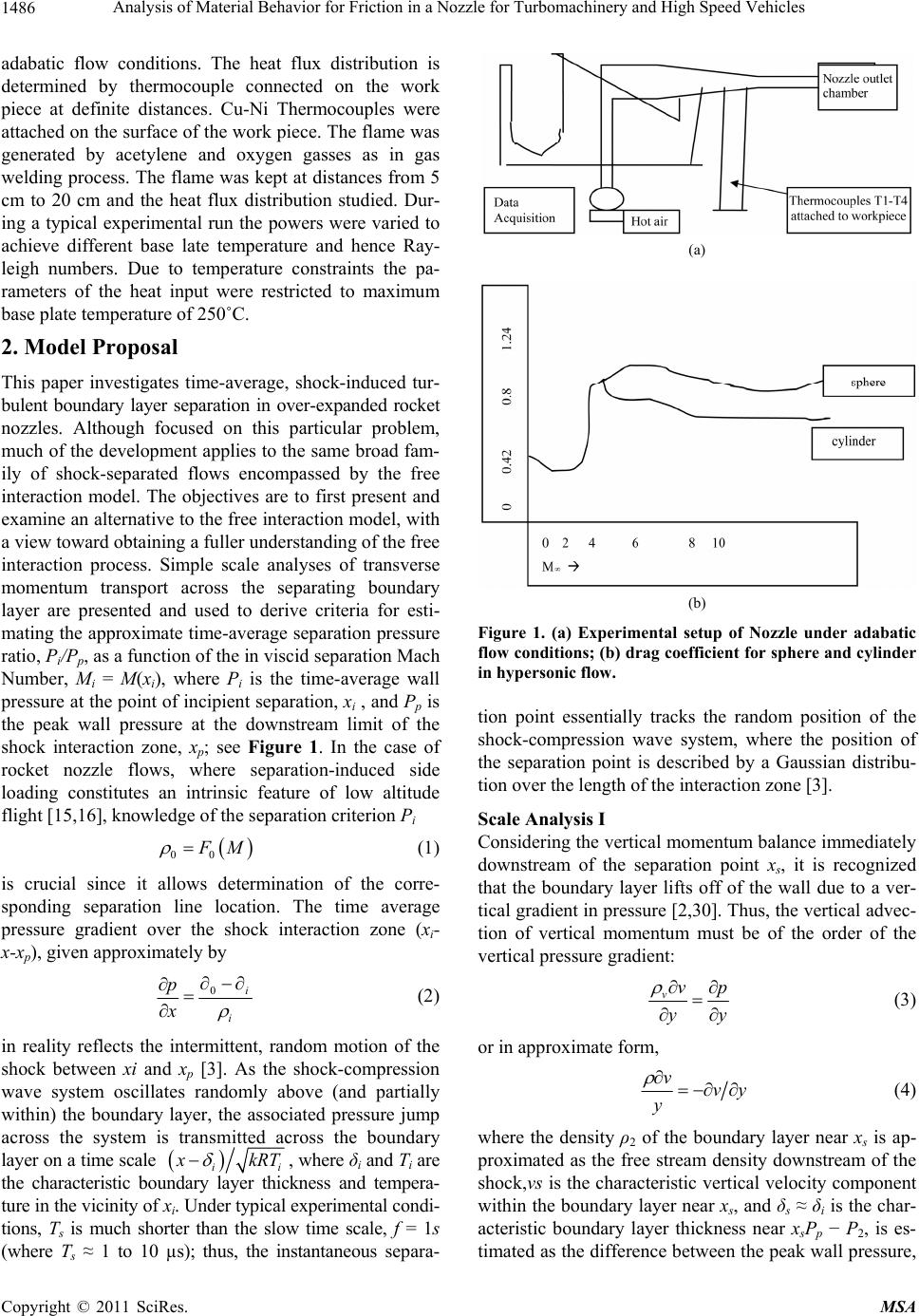
Experimental Setup
Figure 1 shows the Experimental setup of Nozzle under
Analysis of Material Behavior for Friction in a Nozzle for Turbomachinery and High Speed Vehicles
1486
adabatic flow conditions. The heat flux distribution is
determined by thermocouple connected on the work
piece at definite distances. Cu-Ni Thermocouples were
attached on the surface of the work piece. The flame was
generated by acetylene and oxygen gasses as in gas
welding process. The flame was kept at distances from 5
cm to 20 cm and the heat flux distribution studied. Dur-
ing a typical experimental run the powers were varied to
achieve different base late temperature and hence Ray-
leigh numbers. Due to temperature constraints the pa-
rameters of the heat input were restricted to maximum
base plate temperature of 250˚C.
2. Model Proposal
This paper investigates time-average, shock-induced tur-
bulent boundary layer separation in over-expanded rocket
nozzles. Although focused on this particular problem,
much of the development applies to the same broad fam-
ily of shock-separated flows encompassed by the free
interaction model. The objectives are to first present and
examine an alternative to the free interaction model, with
a view toward obtaining a fuller understanding of the free
interaction process. Simple scale analyses of transverse
momentum transport across the separating boundary
layer are presented and used to derive criteria for esti-
mating the approximate time-average separation pressure
ratio, Pi/Pp, as a function of the in viscid separation Mach
Number, Mi = M(xi), where Pi is the time-average wall
pressure at the point of incipient separation, xi , and Pp is
the peak wall pressure at the downstream limit of the
shock interaction zone, xp; see Figure 1. In the case of
rocket nozzle flows, where separation-induced side
loading constitutes an intrinsic feature of low altitude
flight [15,16], knowledge of the separation criterion Pi

00
F
M
(1)
is crucial since it allows determination of the corre-
sponding separation line location. The time average
pressure gradient over the shock interaction zone (xi-
x-xp), given approximately by
0i
i
p
x

(2)
in reality reflects the intermittent, random motion of the
shock between xi and xp [3]. As the shock-compression
wave system oscillates randomly above (and partially
within) the boundary layer, the associated pressure jump
across the system is transmitted across the boundary
layer on a time scale

ii
(a)
(b)
Figure 1. (a) Experimental setup of Nozzle under adabatic
flow conditions; (b) drag coefficient for sphere and cylinder
in hypersonic flow.
tion point essentially tracks the random position of the
shock-compression wave system, where the position of
the separation point is described by a Gaussian distribu-
tion over the length of the interaction zone [3].
Scale Analysis I
Considering the vertical momentum balance immediately
downstream of the separation point xs, it is recognized
that the boundary layer lifts off of the wall due to a ver-
tical gradient in pressure [2,30]. Thus, the vertical advec-
tion of vertical momentum must be of the order of the
vertical pressure gradient:
vvp
yy
(3)
or in approximate form,
vvy
y
 (4)
where the density ρ2 of the boundary layer near xs is ap-
proximated as the free stream density downstream of the
shock,vs is the characteristic vertical velocity component
within the boundary layer near xs, and δs δi is the char-
acteristic boundary layer thickness near xsPp P2, is es-
timated as the difference between the peak wall pressure,
x
kRT
, where δi and Ti are
the characteristic boundary layer thickness and tempera-
ture in the vicinity of xi. Under typical experimental condi-
tions, Ts is much shorter than the slow time scale, f = 1s
(where Ts 1 to 10 µs); thus, the instantaneous separa-
Copyright © 2011 SciRes. MSA
Analysis of Material Behavior for Friction in a Nozzle for Turbomachinery and High Speed Vehicles1487
Pp, in the vicinity of xp and the free stream pressure im-
mediately downstream of the oblique shock. The density
estimate in (4) recognizes that the boundary layer has
passed through the compression wave system at the foot
of the oblique shock.
Eliminating δs from (4) and solving for vs yields

1
s
p
vv1

 (5)
From Figure 2, we note that at the separation point, vs
is related to the characteristic horizontal velocity com-
ponent, us by
1
1
tan ,
v
u
(6)
where θ is the characteristic angle of deflection between
the separating boundary layer and the nozzle wall. The
magnitude of us is estimated by again noting that the
boundary layer flow has passed through the compression
wave system at the foot of the oblique shock and that, as
indicated in Figure 2, the time average turbulent bound-
ary layer velocity profile is nearly flat. Thus, us is on the
order of the x-component (U2) of the inviscid flow veloc-
ity (v2) immediately downstream of the oblique shock:
2
2cos
xv
uu
(7)
Using the ideal gas relation, ρ2 = kP 2/(kRT2), and in-
serting (5) in (6) we then obtain
0.5
2
22
1
tan p
x
Mk



(8)
where M2x = M2 cos θ, and M2 is the in viscid flow Mach
Number immediately downstream of the oblique shock.
Rewriting Pp/P2 as (Pp/P1)(P1/P2) and solving (8) for
Pp/P1 finally yields
Figure 2. Plot of nose length vs friction adiabatic coefficient
of the nozzle.
1
22
2
2
1
1sin
p
P
p
kM
1
(9)
Identifying P1/Pp as the critical wall pressure ratio at
which separation occurs, i.e., P1/Pp Pi/Pp, noting that
M2 is given by the oblique shock relation


22
2
2
222
2
1sin 2
2sin 21
y
kM k
MkM k
1

 (10)
and recognizing that Mi M1, where M1 is the free stream
Mach Number immediately upstream of the oblique
shock, it is seen that (9) provides an explicit, physically-
based relationship between Pi/Pp and the pressure ratio,
P1/P2, across the oblique shock. The next scale analysis
refines the estimates for stream wise inertia and cross-
layer pressure gradient, and leads to a near-identity be-
tween Pi/Pp and P1/P2.
2.1. Optimization of Contour Nozzle Design
Including Viscous Effects
Here we present a genetic algorithm for design of Mach
12 contoured Nozzle. The objective is to produce a uni-
form velocity (Mach Number) over the entrance region
in the nozzle exit plane and to limit the flow angularity at
the exit plane, over the same region within a given limit.
At hypersonic wind tunnel nozzles with Mach Numbers
greater than 8 are dominated with strong viscous effects,
the nozzle contour generated by conventional method of
characteristics does not meet the design requirements
when boundary layer corrections are made. In the present
work parallel Aerodynamic simulator code (PARAS) or
FLUENT. The former uses the surface oriented mesh
system to simulate the flow inside the axisymmetric noz-
zle. The code solves Navier stokes equations using a Fi-
nite volume approach and is convenient and fast. To rep-
resent the nozzle contour generated by conventional
method of characteristics. CFD solutions are used to
evaluate the objective function in each function evalua-
tion of the Genetic Algorithm (GA) process. To represent
the nozzle contour in terms of certain parameter vector
P(p1, p2, ···, pn) the nozzle contour is divided into 5 seg-
ments and is represented as follows.:
For 0 < x x1 r = a0 + a1x + a2x2 + a3x3
x1 < x x2 r = a0 + a1x + a2x2 + a3x3
x2 < x x3 r = a0 + a1x + a2x2 + a3x3
x3 < x x4 r = a0 + a1x + a2x2 + a3x3
x4 < x x5 r = a0 + a1x + a2x2 + a3x3
The above five cubic spheres result in 20 coefficients
(a0, a1, ···, a20) assuming that the locations x1, x2, ···, x5
are known. The slopes at the nozzle throat and the exit
plane are assumed to be zero. The continuity of radius,
slope and curvature at the four interfaces give 4 condi-
Copyright © 2011 SciRes. MSA
Analysis of Material Behavior for Friction in a Nozzle for Turbomachinery and High Speed Vehicles
1488
tions. With these 20 conditions, the above set of linear
simultaneous equations is solved using the Gauss Siedel
method. After getting the coefficients a0, ···, a19 the noz-
zle contour can be determined. The length of the nozzle
is also kept as a floating parmeter. A constant inlet Mach
Number of unity has been taken and the tunnel operating
conditions have been taken as p0 = 68 KSC, T0 = 1500 K
and ratio of specific heats
= 1.31. Besides the radii rth,
r1, r2, r3, and r4 the length of the nozzle L (=x5) is also
considered as a parameter. The nozzle exit radius is 0.5
m which is the test section radius is 0.5 m which is the
test section radius, and is fixed. The nominal values of
these parameters are arrived at using the MOC contour
with the boundary layer correction.
The objective function consists of 2 parts. First part
takes into account the deviation of actual Mach Number
Mact from the target Mach Number Mtar (=12)and the sec-
ond part of the deviation of flow angularity
act from the
target flow angularity
tar (0.2 deg). These are evaluated
at the core of the nozzle exit. Thus we have (MtarMach
at target)


22
acttaract tar
Obj1 M
PN MM


 


where P is the parameter vector and N is number of grid
cells in the core of the nozzle exit. Values of
M and
are taken as 0.7 and 0.28 respectively, which are the
weighting factors.
Figure 7 shows the Objective function as defined
above with number of generations. It is seen that the ob-
jective function falls by 30% in about 68 generations.
2.2. Modeling of Hypersonic Flows
The Navier Stokes equations for the hypersonic flow are
given by the continuity and momentum equations.
Continuity Equation
0
uv
xy


 (11)
vvgk
uv T
x
yv
 

 x
(12)
where volumetric heat sources (x, y, z) represents the
contribution of frictional heating. The parameters
Cp &
ke may depend on y & z but remain independent of x.
More importantly the contributing of axial conduction
deferred to the subsequent is neglected, hence Equation
(4) reduces

22
22
22 0
uT vTTTuv
xx KCp
xy

 
 

 
 (13)
When these are non dimensionalized g the following
definitions of variables
** **
inf
*2*
, , , ,
=, =
x
xl yyl zzl uuV
PP v

 

we get
** 0u
 (14)
*
0u
**
(15)
*
*0
p
u
 (16)
For flow tangent to body V·n = 0.
Let nx, ny, nz be the vector. Using the final pressure ra-
tio equations can be derived for the nozzle as below.
Consider the hyperonic flow over a given body in the
limit of large M. The flow is again governed by Equa-
tions (4)-(6) we get the Bcondns as

2
2sinp

(17)
2
1
1
(18)

2
212sin1u


(19)
2
2sin 1v

(20)
From this consideration we can seethe Mach Number
is independent and this follows from the governing Equa-
tions of motion with the appropriate BCs. Written in
limit of high Mach Number. Hence when the free stream
Mach Number is very high the dimensionless variables
become independent on Mach Number, this trend applies
to any quantities derived from these dimensionless vari-
ables. The drag coefficient follows a plot as in Figure 1
below.
Examining the governing flow Equation upon which
hyperbolic similarity is based (Equations of continuity &
motion) in dimensionless form)The similarity principle
holds for both irrotational and rotational flow as shown
in Figure 2 where the two curves for irrotational & rota-
tional flow overlap each other. The surface pressure dis-
tribution is shown in Figure below.
The sphere drag achieve Mach no independence at
lower Ma. For blunt cone end ogive cylinders the veloc-
ity distributions is given below.
The maximum location of the shock is btaies as shown
in Figures 4 and 5.
The main point in this discussion however, to find the
farthest shock location downstream. Figure 5 shows the
possible as function of retreat of the location of the shock
wave from the maximum location. When the entrance
Mach Number is infinity, P2, if the shock location is at
the Maximum length, than shock at M2 < 1 results in
Copyright © 2011 SciRes. MSA
Analysis of Material Behavior for Friction in a Nozzle for Turbomachinery and High Speed Vehicles1489
4fL/D = 0.3 and possible.
The proposed procedure is based on Figure 5.
1) Calculated the extra 4fL/D and subtract the actual
extra 4fL/D assuming shock at the left side (at the max
length).
2) Calculated the extra 4fL/D and subtract the actual
extra 4fL/D D assuming shock at the right side (at the
entrance).
3) According to the positive or negative utilizes your
root finding procedure.
From numerical point of view, the Mach Number
equal infinity when left side assume result in infinity
length of possible extra (the whole flow in the tube is
subsonic). To overcome this numerical problem it is
suggested to start the calculation from distance from the
right hand side.
Let us denote
4fL/D > 4fLmax /D~0.34
Note that 4fL/D < 4fL/D ma x is smaller than P2. The re-
quirement that has to satisfied is that denote as difference
between the maximum possible of length in which the
flow supersonic achieved and the actual length in which
the flow is supersonic as in Figure 8. The retreating length
is expressed as subsonic but as the Figure 8 shows the
entrance Mach Number, M1 is reduced after the maximum
length is exceeded. From numerical point of view, the
Mach Number equal infinity when left side assume result
in infinity length of possible extra (the whole flow in the
tube is subsonic). To overcome this numerical problem it
is suggested to start the calculation from distance from the
right hand side.
3. Results and Discussion
Figure 2 shows the plot of Nose length vs friction adia-
batic coefficient of the nozzle Figure 3 gives the Pres-
sure distributions for ogive cylinders: illustration of hy-
personic similarity a) K = 0.5 b) K = 1.0. Figure 4 shows
the Surface pressure distribution at x/Rn = 8
= 20*,
=
1.67, Re = 86000,
c = 15. Figure 5 Pressure distribution
over blunt nosed cone, compared with pointed cone. Fig-
ure 6 shows the Fanno flow characteristics.
Figure 3. Pressure distributions for ogive cylinders: illus-
tration of hypersonic similarity (a) K = 0.5 (b) K = 1.0.
Figure 4. Surfac e pressure distribution at x/Rn = 8,
= 20*,
= 1.67, Re = 86000,
c = 15.
Figure 5. Pressure distribution over blunt nosed cone, com-
pared with pointed cone.
Figure 7 depicts the Mach Number variation with fric-
tion headloss. Figure 8 gives the depiction of pressure
drop variation with friction headloss. At hypersonic wind
tunnel nozzles with Mach Numbers greater than 8 are
dominated with strong viscous effects, the nozzle contour
generated by conventional method of characteristics does
not meet the design requirements when boundary layer
corrections are made. In the present work parallel aero-
dynamic simulator code (PARAS) or FLUENT. The re-
quirement that has to satisfied is that denote as difference
between the maximum possible of length in which the
flow supersonic achieved and the actual length in which
the flow is supersonic as in Figure 8. From numerical
point of view, the Mach Number equal infinity when left
side assume result in infinity length of possible extra (the
whole flow in the tube is subsonic).
4. Conclusions and Suggestions
Time-average, shock-induced, turbulent boundary layer
separation has been investigated using a combination of
heuristics, simple analytical models, and experiments,
with a focus on separation in over expanded rocket noz-
zles. Two simple scaling analyses are presented in which
Copyright © 2011 SciRes. MSA
Analysis of Material Behavior for Friction in a Nozzle for Turbomachinery and High Speed Vehicles
Copyright © 2011 SciRes. MSA
1490
Figure 8. Plot of Pressure ratio in the nozzle to aspect ratio
of nozzle.
Figure 6. Fanno flow characteristic s. sure ratio is, to a good approximation, determined by the
oblique shock pressure ratio.
REFERENCES
[1] G. Settles, “Details of a Shock-Separated Turbulent Bound-
ary Layer at a Compression Corner,” AIAA Journal, Vol.
14, No. 12, 1976, pp. 1709-1715. doi:10.2514/3.61513
[2] D. R. Chapman, D. M. Kuehn and H. K. Larson, “Inves-
tigation of Separated Flows in Supersonic and Subsonic
Streams with Emphasis on the Effect of Transition,”
NACA Report 1356, 1958.
[3] M. E. Erengil and D. S. Dolling, “Correlation of Separa-
tion Shock Motion with Pressure Fluctuations in the In-
coming Boundary Layer,” AIAA Journal, Vol. 29, No. 11,
1990, pp. 1868-1877. doi:10.2514/3.10812
[4] D. S. Dolling and L. Brusniak, “Separation Shock Motion
in Fin, Cylinder, and Compression Ramp-Induced Turbu-
lent Interactions,” AIAA Journal, Vol. 27, No. 6, 1988, pp.
734-742. doi:10.2514/3.10173
[5] J. Ackeret, F. Feldman and N. Rott, “Investigations of
Compression Shocks and Boundary Layers in Gases
Moving at High Speed,” NACA TM No. 1113, 1947.
Figure 7. Mach Number variation with friction head loss.
[6] D. S. Dolling and D. R. Smith, “Separation Shock Dynam-
ics in Mach 5 Turbulent Interactions Induced by Cylin-
ders,” AIAA Journal, Vol. 27, No. 12, 1989, pp. 1698-1706.
doi:10.2514/3.10323
separation is viewed as reflecting a balance between
streamwise boundary layer inertia and the cross-layer
pressure gradient. These lead to two theoretical expres-
sions for the time average separation pressure ratio,
stated as a function of the inviscid Mach Number at the
point of incipient separation. In both models, explicit
relationships between the separation pressure ratio (at the
wall) and the classical oblique shock ratio are obtained;
the second model, representing a refinement of the first,
emonstrates for the first time that the separation pres-
[7] R. A. Gramann and D. S. Dolling, “Detection of Turbu-
lent Boundary-Layer Separation Using Fluctuating Wall
Pressure Signals,” AIAA Journal, Vol. 28, No. 6, 1989, pp.
1052-1056. doi:10.2514/3.25164
[8] J. Ostlund, “Flow Processes in Rocket Engine Nozzles
with Focus on Flow-Separation and Side-Loads,” Licen-
tiate Thesis, Royal Inst. of Technology, Stockholm,
TRITA-MEK, Technique Report, 2002, p. 1112.
d