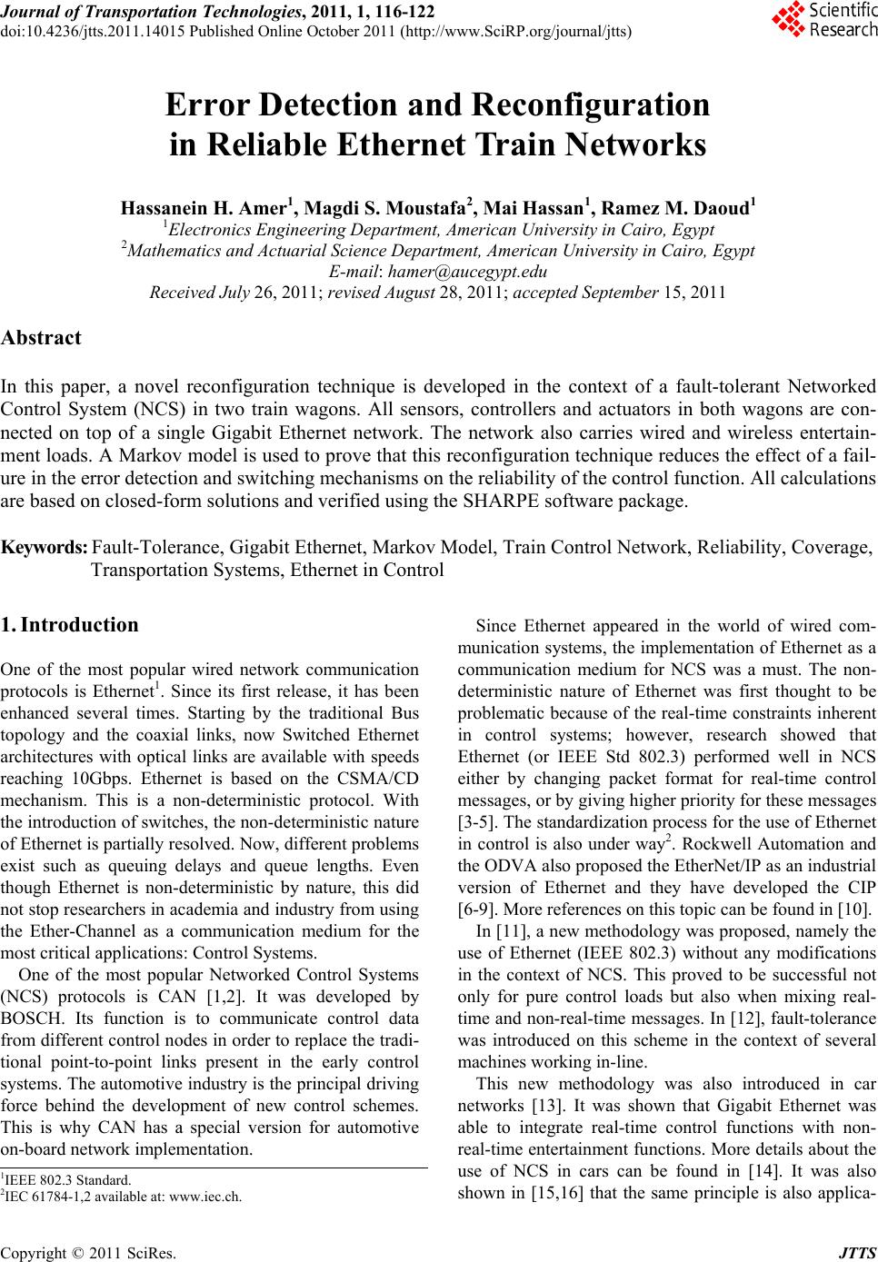
 Journal of Transportation Technologies, 2011, 1, 116-122 doi:10.4236/jtts.2011.14015 Published Online October 2011 (http://www.SciRP.org/journal/jtts) Copyright © 2011 SciRes. JTTS Error Detection and Reconfiguration in Reliable Ethernet Train Networks Hassanein H. Amer1, Magdi S. Moustafa2, Mai Hassan1, Ramez M. Daoud1 1Electronics Engineering Department, American University in Cairo, Egypt 2Mathemati cs an d Actuarial Sci e nce Department, American University in Cairo, Egypt E-mail: hamer@aucegypt.edu Received July 26, 2011; revised August 28, 2011; accepted September 15, 2011 Abstract In this paper, a novel reconfiguration technique is developed in the context of a fault-tolerant Networked Control System (NCS) in two train wagons. All sensors, controllers and actuators in both wagons are con- nected on top of a single Gigabit Ethernet network. The network also carries wired and wireless entertain- ment loads. A Markov model is used to prove that this reconfiguration technique reduces the effect of a fail- ure in the error detection and switching mechanisms on the reliability of the control function. All calculations are based on closed-form solutions and verified using the SHARPE software package. Keywords: Fault-Tolerance, Gigabit Ethernet, Markov Model, Train Control Network, Reliability, Coverage, Transportation Systems, Ethernet in Control 1. Introduction One of the most popular wired network communication protocols is Ethernet1. Since its first release, it has been enhanced several times. Starting by the traditional Bus topology and the coaxial links, now Switched Ethernet architectures with optical links are available with speeds reaching 10Gbps. Ethernet is based on the CSMA/CD mechanism. This is a non-deterministic protocol. With the introduction of switches, the non-deterministic nature of Ethernet is partially resolved. Now, different problems exist such as queuing delays and queue lengths. Even though Ethernet is non-deterministic by nature, this did not stop researchers in academia and industry from using the Ether-Channel as a communication medium for the most critical applications: Control Systems. One of the most popular Networked Control Systems (NCS) protocols is CAN [1,2]. It was developed by BOSCH. Its function is to communicate control data from different control nodes in order to replace the tradi- tional point-to-point links present in the early control systems. The automotive industry is the principal driving force behind the development of new control schemes. This is why CAN has a special version for automotive on-board network implementation. Since Ethernet appeared in the world of wired com- munication systems, the implementation of Ethernet as a communication medium for NCS was a must. The non- deterministic nature of Ethernet was first thought to be problematic because of the real-time constraints inherent in control systems; however, research showed that Ethernet (or IEEE Std 802.3) performed well in NCS either by changing packet format for real-time control messages, or by giving higher priority for these messages [3-5]. The standardization process for the use of Ethernet in control is also under way2. Rockwell Automation and the ODVA also proposed the EtherNet/IP as an industrial version of Ethernet and they have developed the CIP [6-9]. More references on this topic can be found in [10]. In [11], a new methodology was proposed, namely the use of Ethernet (IEEE 802.3) without any modifications in the context of NCS. This proved to be successful not only for pure control loads but also when mixing real- time and non-real-time messages. In [12], fault-tolerance was introduced on this scheme in the context of several machines working in-line. This new methodology was also introduced in car networks [13]. It was shown that Gigabit Ethernet was able to integrate real-time control functions with non- real-time entertainment functions. More details about the use of NCS in cars can be found in [14]. It was also shown in [15,16] that the same principle is also applica- 1IEEE 802.3 Standard. 2IEC 61784-1,2 available at: www.iec.ch. 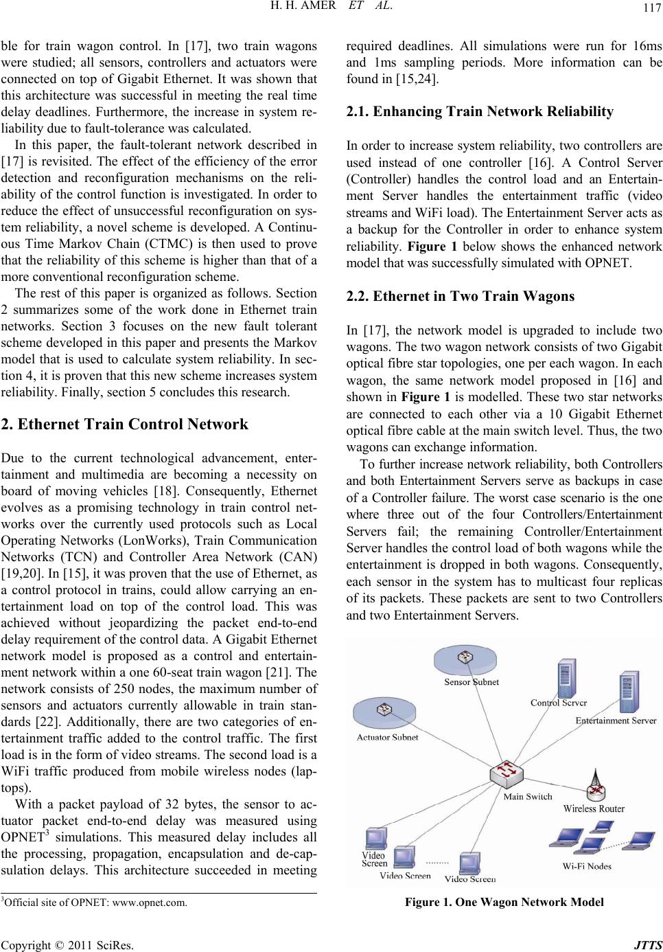 117 H. H. AMER ET AL. ble for train wagon control. In [17], two train wagons were studied; all sensors, controllers and actuators were connected on top of Gigabit Ethernet. It was shown that this architecture was successful in meeting the real time delay deadlines. Furthermore, the increase in system re- liability due to fault-tolerance was calculated. In this paper, the fault-tolerant network described in [17] is revisited. The effect of the efficiency of the error detection and reconfiguration mechanisms on the reli- ability of the control function is investigated. In order to reduce the effect of unsuccessful reconfiguration on sys- tem reliability, a novel scheme is developed. A Continu- ous Time Markov Chain (CTMC) is then used to prove that the reliability of this scheme is higher than that of a more conventional reconfiguration scheme. The rest of this paper is organized as follows. Section 2 summarizes some of the work done in Ethernet train networks. Section 3 focuses on the new fault tolerant scheme developed in this paper and presents the Markov model that is used to calculate system reliability. In sec- tion 4, it is proven that this new scheme increases system reliability. Finally, section 5 concludes this research. 2. Ethernet Train Control Network Due to the current technological advancement, enter- tainment and multimedia are becoming a necessity on board of moving vehicles [18]. Consequently, Ethernet evolves as a promising technology in train control net- works over the currently used protocols such as Local Operating Networks (LonWorks), Train Communication Networks (TCN) and Controller Area Network (CAN) [19,20]. In [15], it was proven that the use of Ethernet, as a control protocol in trains, could allow carrying an en- tertainment load on top of the control load. This was achieved without jeopardizing the packet end-to-end delay requirement of the control data. A Gigabit Ethernet network model is proposed as a control and entertain- ment network within a one 60-seat train wagon [21]. The network consists of 250 nodes, the maximum number of sensors and actuators currently allowable in train stan- dards [22]. Additionally, there are two categories of en- tertainment traffic added to the control traffic. The first load is in the form of video streams. The second load is a WiFi traffic produced from mobile wireless nodes (lap- tops). With a packet payload of 32 bytes, the sensor to ac- tuator packet end-to-end delay was measured using OPNET3 simulations. This measured delay includes all the processing, propagation, encapsulation and de-cap- sulation delays. This architecture succeeded in meeting required deadlines. All simulations were run for 16ms and 1ms sampling periods. More information can be found in [15,24]. 2.1. Enhancing Train Network Reliability In order to increase system reliability, two controllers are used instead of one controller [16]. A Control Server (Controller) handles the control load and an Entertain- ment Server handles the entertainment traffic (video streams and WiFi load). The Entertainment Server acts as a backup for the Controller in order to enhance system reliability. Figure 1 below shows the enhanced network model that was successfully simulated with OPNET. 2.2. Ethernet in Two Train Wagons In [17], the network model is upgraded to include two wagons. The two wagon network consists of two Gigabit optical fibre star topologies, one per each wagon. In each wagon, the same network model proposed in [16] and shown in Figure 1 is modelled. These two star networks are connected to each other via a 10 Gigabit Ethernet optical fibre cable at the main switch level. Thus, the two wagons can exchange information. To further increase network reliability, both Controllers and both Entertainment Servers serve as backups in case of a Controller failure. The worst case scenario is the one where three out of the four Controllers/Entertainment Servers fail; the remaining Controller/Entertainment Server handles the control load of both wagons while the entertainment is dropped in both wagons. Consequently, each sensor in the system has to multicast four replicas of its packets. These packets are sent to two Controllers and two Entertainment Servers. Figure 1. One Wagon Network Model 3Official site of OPNET: www.opnet.com. Copyright © 2011 SciRes. JTTS  H. H. AMER ET AL. 118 2 E - In the context of two wagons, the main metric under study is the maximum sensor-to-actuator packet end-to- end delay. This measured delay includes all the process- ing, propagation, encapsulation and de-capsulation de- lays. OPNET simulations showed that this architecture, when fault free, is successful in meeting required dead- lines. The worst case scenario was also successfully simulated with OPNET; one controller handled the con- trol load of both wagons while the entertainment was completely dropped. 3. Novel Error Detection/Reconfiguration Scheme The fault-tolerance mentioned above is expected to in- crease system reliability. Let Rcontrol-FT be the reliability of the control function of both wagons. Furthermore, as- sume that the controllers in both wagons are identical. The same assumption will also be valid for the Enter- tainment Servers in both wagons. Let RK be the reliabil- ity of any of the two controllers (K1 and K2) and RE be the reliability of any of the two Entertainment Servers (E1 and E2). The reliability R(t) is defined as the prob- ability that a Controller/Entertainment Server is func- tional at time t. Hence 2 control-FTK E R1 1R1R (1) Note that (1−RK) is the unreliability of a Controller while (1−RE) is the unreliability of an Entertainment Server. (1−R(t)) is the probability that the system has failed at time t. Intuitively, the fault tolerant architecture described in the previous section should increase the reliability of the control function in the context of two wagons. Without any fault tolerance, the control function will fail as soon as either of the two Controllers fails. Let this architecture have a reliability Rcont. 2 cont K RR (2) The time to failure of electronic equipment has been historically assumed to be exponentially distributed [24, 25]. The failure rate will therefore be constant. Let λK be the failure rate of any of the two Controllers and let λE be the failure rate of any of the two Entertainment Servers. The relation between the reliability and the failure rate is as follows [24, 25]: K -λtλt KE Rt =e;Rt =e (3) By comparing Rcontrol-FT and Rcont, it was shown in [17] that fault-tolerance had increased system reliability as expected. This increase in reliability relies on the implicit as- sumption that the switching tasks from a failed Control- ler/Entertainment Server to another operational Control- ler/Entertainment Server will always be successful. Next, the details of this switching mechanism are explained in the context of a K failing and E taking over its tasks. In the fault-free situation, all packets sent from the sensors are received by both servers: K and E. Only K responds to these packets, calculates the necessary control packet and sends it to the designated actuator node. A watchdog in the form of “live” packets is continuously exchanged between K and E. When E detects a missing watchdog (which indicates the failure of K), it gets into the loop to replace the inactive K and sends the control packet to the designated actuator. The control procedure running on E and used to backup K in case of failure, must be de- signed to accommodate the loss of one packet. Also, the control system must not be susceptible to the loss of one control packet. This is to overcome the probability to loose, at most, one packet during the switchover between K and E. A trivial solution in this case would be the “keep previous sample” technique. In this procedure, the actuator applies to the plant the previous action until a new control word is received. This switching mechanism is susceptible to failure. For example, if the inter-communication between K and E fails, E will assume that K has failed and hence, will take over its tasks. Such a conflict will cause a system failure. More details about unsuccessful reconfiguration can be found in [26]. Furthermore, the reconfiguration process in control systems is covered in [27]. Since the success of the reconfiguration process is not guaranteed, it has to be taken into account in the reliabil- ity model. In the literature, the probability of successful detection/reconfiguration is called coverage [24,25,28]. The coverage is a parameter determined by the user and incorporated in reliability/availability models. It is known that a small mistake in the calculation of the cov- erage can lead to misleading reliability/availability esti- mations [25]. Also, system reliability is expected to de- crease with a decrease in coverage. A reconfiguration scheme is described next that aims at reducing the effect of coverage on the reliability of the control function Rcontrol-Ft. 3.1. Details of the New Scheme Let K1 and K2 be the Controllers in the two wagons. Also, let E1 and E2 be the two Entertainment Servers. If one of the two controllers K1 or K2 fails, the other con- troller carries the control load for both wagons. Also, as a precautionary measure, the entertainment load is shut down as soon as one of the controllers fails. If one or both entertainment servers fail while both controllers are still operational, the entertainment is simply dropped without any need for reconfiguration. This strategy is Copyright © 2011 SciRes. JTTS  H. H. AMER ET AL. Copyright © 2011 SciRes. JTTS 119 expected to produce a higher reliability when compared to a conventional strategy where the failure of any con- troller/entertainment server necessitates system recon- figuration. A Markov model is developed next to calcu- late system reliability based on the strategy described above. Figure 2 shows this Markov model. The name of any state indicates the operational components in that state. Remember that λE is the failure rate of the Entertainment Server and λK is the failure rate of the Controller. The initial state is 2C2E. This is the error-free state; both controllers and both servers are operational. A failure of one of the controllers takes the system to state 1C2E. This transition will only occur if the reconfiguration is successful and the operational controller is able to take over the tasks of the failed controller and handle the en- tire control function in both wagons. This is why the transition rate from state 2C2E to state 1C2E is 2cλK. If the reconfiguration is not successful, the control function fails and the system moves to state F (i.e., the control function failure state) at a rate of 2λK (1c). Also, a fail- ure of one of the Entertainment servers moves the model to state 2C1E. Since two servers can fail, the transition rate from 2C2E to 2C1E is 2λE. The coverage does not affect this transition as mentioned above. In state 1C2E, a failure of one of the two entertain- ment servers moves the system to state 1C1E at a rate of 2λE. The failure of the remaining operational controller takes the system to state 2E at a rate of cλK and to state F at a rate of (1c)λK. In state 2C1E, the failure of C1 or C2 moves the sys- tem to state 1C1E; the transition rate is 2cλK. If the re- configuration is not successful, the system moves to state F at a rate of 2λK(1c). The failure of the remaining En- tertainment server takes the system to state 2C at a rate of λE. Here again, the reconfiguration process is not in- volved because the entertainment is shut off and the con- trol function is not affected. In state 2C, E1 and E2 have failed but the control function has not been affected since C1 and C2 are both operational. If either C1 or C2 fails, the model moves to state 1C; the control of both wagons is handled by the remaining operational controller. The coverage affects this transition and therefore, the transition rate from 2C to 1C is 2cλK; also, the transition from 2C to F is 2(1c)λK. Figure 2. Markov model.  H. H. AMER ET AL. 120 K E 2λ+λ2λ2λ0000021λcc t/dP dt tP EK 2λ+λ et P E λt 1 e K 2λt EK EK 1C1E λ+2λt2λ+λt ee EK EKK EKE KK EKE KK KK EKE KK EE KK EE 0λ2λ0λ2λ00021λ 002λλ 02λλ001λ 0002λ002λ021λ T= 0000λλ 0λλ1λ 000002λ02λ21 λ 000000λ0λ 0000000λλ 000000000 cc cc cc cc cc In state 2E, both Controllers have already failed and one the Entertainment Servers is controlling both wagons. If either E1 or E2 fails, the control function is switched to the remaining operational server. Here again, the coverage is involved in the transition as shown in Figure 2. In state 1C1E, the situation is more complex. One En- tertainment Server has already failed as well as one of the Controllers. The remaining Controller is in charge of the control function of both wagons and the entertainment is turned off in both wagons. The remaining server acts as a hot stand-by for the remaining Controller. If the Enter- tainment Server fails, the system moves to state 1C without affecting the control function; consequently, the transition rate from 1C1E to 1C is λE. However, if the Controller fails, the control function is switched to the Entertainment Server and the coverage affects the transi- tion; the transition rate from state 1C1E to state 1E is cλK and the one from 1C1E to F is (1c)λK. Finally, in state 1E, the failure of the remaining entertainment server causes a system failure at a rate of λE. The same argu- ment applies for state 1C where the failure of the re- maining Controller causes a system failure at a rate of λk. The system can be described by the Chapman-Kol- mogorov equations. The row vectors and are obvious and the transition matrix T is as shown above. Given that the system starts in state 2C2E, these dif- ferential equations can be solved and the probabilities of being in each of the model states can be obtained in closed form. System reliability is the probability of not being in state F. 2C2E EK λ+2λt 2C1E =2eP (4) (5) 2 1C2E 21 EK K tt Pce e (6) EK EK 2λ+λt2λ+λt 2C =e2e +eP (7) EK EK 2λ+λtλ+λt e+e 4Pc (8) EKK 2λt2λtλt 2 2E =e20.5ee +1Pc (9) KEK E KE K 2λ+λtλ+2λt 2λ+2λt2λt =4 e+2 e 2e2e Pc c cc 1C KE K λ+λtλt 4e+2ecc (10) EKE K EK EK EE 2λ+λt2λ+2λt 1E λ+2λtλ+λt 2λtλt 3 =eX eY +e2e4c e2+eW P c c 22 (11) where: 23 KE KE 4λ+4 λ Xλ+λ cc , 23 KE KE 4λ+2 λ Y2λ+λ cc 22 E 23 KE 22λ+λ4λ+λ W=2+2 +2λ+ cc cc cc KE K KE λλ+λ 4. Efficiency of the New Scheme In this section, it is proved that the novel reconfiguration scheme described above, increases system reliability (Rcontrol-FT). Conventionally, the entire system undergoes reconfiguration in the event of a controller/Entertainment Server failure. Such a system would be modeled by the CTMC depicted in Figure 3. In this model, it is assumed, for simplicity, that λK = λE = λ. Consequently, the failure of any of the four controllers/servers may cause a system failure with a probability (1c), where c is the coverage parameter discussed above. Any state in Figure 3 indi- cates the number of operational components in that state. A component can be a controller or an entertainment server. This is why the initial state is called “4” and the final (absorbing) state is called “0”. Moving from state “i” to state “i1” (for i = 2 to 4) occurs when one of the operational components fails and the recovery is suc- cessful (with a probability c). Rcontrol-FT for this conven- Copyright © 2011 SciRes. JTTS 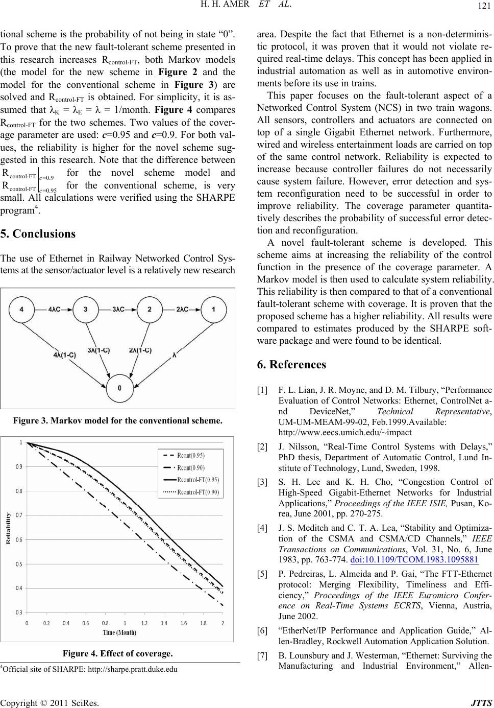 121 H. H. AMER ET AL. tional scheme is the probability of not being in state “0”. To prove that the new fault-tolerant scheme presented in this research increases Rcontrol-FT, both Markov models (the model for the new scheme in Figure 2 and the model for the conventional scheme in Figure 3) are solved and Rcontrol-FT is obtained. For simplicity, it is as- sumed that λK = λE = λ = 1/month. Figure 4 compares Rcontrol-FT for the two schemes. Two values of the cover- age parameter are used: c=0.95 and c=0.9. For both val- ues, the reliability is higher for the novel scheme sug- gested in this research. Note that the difference between control-FT =0.9 Rc for the novel scheme model and control-FT=0.95 c for the conventional scheme, is very small. All calculations were verified using the SHARPE program4. R 5. Conclusions The use of Ethernet in Railway Networked Control Sys- tems at the sensor/actuator level is a relatively new research Figure 3. Markov model for the conventional scheme. Figure 4. Effect of coverage. area. Despite the fact that Ethernet is a non-determinis- tic protocol, it was proven that it would not violate re- quired real-time delays. This concept has been applied in industrial automation as well as in automotive environ- ments before its use in trains. This paper focuses on the fault-tolerant aspect of a Networked Control System (NCS) in two train wagons. All sensors, controllers and actuators are connected on top of a single Gigabit Ethernet network. Furthermore, wired and wireless entertainment loads are carried on top of the same control network. Reliability is expected to increase because controller failures do not necessarily cause system failure. However, error detection and sys- tem reconfiguration need to be successful in order to improve reliability. The coverage parameter quantita- tively describes the probability of successful error detec- tion and reconfiguration. A novel fault-tolerant scheme is developed. This scheme aims at increasing the reliability of the control function in the presence of the coverage parameter. A Markov model is then used to calculate system reliability. This reliability is then compared to that of a conventional fault-tolerant scheme with coverage. It is proven that the proposed scheme has a higher reliability. All results were compared to estimates produced by the SHARPE soft- ware package and were found to be identical. 6. References [1] F. L. Lian, J. R. Moyne, and D. M. Tilbury, “Performance Evaluation of Control Networks: Ethernet, ControlNet a- nd DeviceNet,” Technical Representative, UM-UM-MEAM-99-02, Feb.1999.Available: http://www.eecs.umich.edu/~impact [2] J. Nilsson, “Real-Time Control Systems with Delays,” PhD thesis, Department of Automatic Control, Lund In- stitute of Technology, Lund, Sweden, 1998. [3] S. H. Lee and K. H. Cho, “Congestion Control of High-Speed Gigabit-Ethernet Networks for Industrial Applications,” Proceedings of the IEEE ISIE, Pusan, Ko- rea, June 2001, pp. 270-275. [4] J. S. Meditch and C. T. A. Lea, “Stability and Optimiza- tion of the CSMA and CSMA/CD Channels,” IEEE Transactions on Communications, Vol. 31, No. 6, June 1983, pp. 763-774. doi:10.1109/TCOM.1983.1095881 [5] P. Pedreiras, L. Almeida and P. Gai, “The FTT-Ethernet protocol: Merging Flexibility, Timeliness and Effi- ciency,” Proceedings of the IEEE Euromicro Confer- ence on Real-Time Systems ECRTS, Vienna, Austria, June 2002. [6] “EtherNet/IP Performance and Application Guide,” Al- len-Bradley, Rockwell Automation Application Solution. [7] B. Lounsbury and J. Westerman, “Ethernet: Surviving the Manufacturing and Industrial Environment,” Allen- 4Official site of SHARPE: http://sharpe.pratt.duke.edu Copyright © 2011 SciRes. JTTS 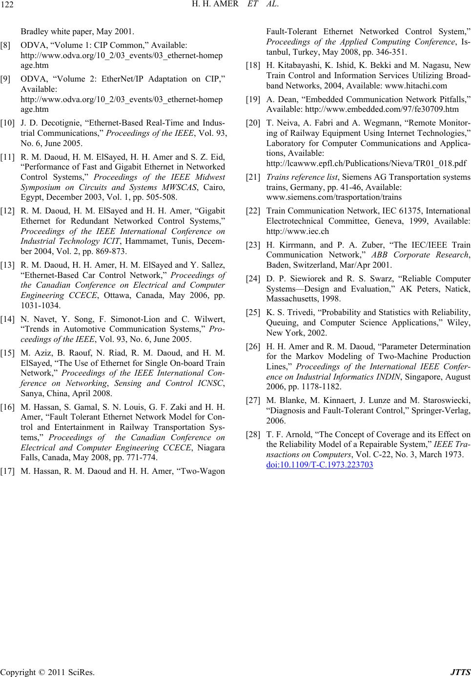 H. H. AMER ET AL. Copyright © 2011 SciRes. JTTS 122 Bradley white paper, May 2001. [8] ODVA, “Volume 1: CIP Common,” Available: http://www.odva.org/10_2/03_events/03_ethernet-homep age.htm [9] ODVA, “Volume 2: EtherNet/IP Adaptation on CIP,” Available: http://www.odva.org/10_2/03_events/03_ethernet-homep age.htm [10] J. D. Decotignie, “Ethernet-Based Real-Time and Indus- trial Communications,” Proceedings of the IEEE, Vol. 93, No. 6, June 2005. [11] R. M. Daoud, H. M. ElSayed, H. H. Amer and S. Z. Eid, “Performance of Fast and Gigabit Ethernet in Networked Control Systems,” Proceedings of the IEEE Midwest Symposium on Circuits and Systems MWSCAS, Cairo, Egypt, December 2003, Vol. 1, pp. 505-508. [12] R. M. Daoud, H. M. ElSayed and H. H. Amer, “Gigabit Ethernet for Redundant Networked Control Systems,” Proceedings of the IEEE International Conference on Industrial Technology ICIT, Hammamet, Tunis, Decem- ber 2004, Vol. 2, pp. 869-873. [13] R. M. Daoud, H. H. Amer, H. M. ElSayed and Y. Sallez, “Ethernet-Based Car Control Network,” Proceedings of the Canadian Conference on Electrical and Computer Engineering CCECE, Ottawa, Canada, May 2006, pp. 1031-1034. [14] N. Navet, Y. Song, F. Simonot-Lion and C. Wilwert, “Trends in Automotive Communication Systems,” Pro- ceedings of the IEEE, Vol. 93, No. 6, June 2005. [15] M. Aziz, B. Raouf, N. Riad, R. M. Daoud, and H. M. ElSayed, “The Use of Ethernet for Single On-board Train Network,” Proceedings of the IEEE International Con- ference on Networking, Sensing and Control ICNSC, Sanya, China, April 2008. [16] M. Hassan, S. Gamal, S. N. Louis, G. F. Zaki and H. H. Amer, “Fault Tolerant Ethernet Network Model for Con- trol and Entertainment in Railway Transportation Sys- tems,” Proceedings of the Canadian Conference on Electrical and Computer Engineering CCECE, Niagara Falls, Canada, May 2008, pp. 771-774. [17] M. Hassan, R. M. Daoud and H. H. Amer, “Two-Wagon Fault-Tolerant Ethernet Networked Control System,” Proceedings of the Applied Computing Conference, Is- tanbul, Turkey, May 2008, pp. 346-351. [18] H. Kitabayashi, K. Ishid, K. Bekki and M. Nagasu, New Train Control and Information Services Utilizing Broad- band Networks, 2004, Available: www.hitachi.com [19] A. Dean, “Embedded Communication Network Pitfalls,” Available: http://www.embedded.com/97/fe30709.htm [20] T. Neiva, A. Fabri and A. Wegmann, “Remote Monitor- ing of Railway Equipment Using Internet Technologies,” Laboratory for Computer Communications and Applica- tions, Available: http://lcawww.epfl.ch/Publications/Nieva/TR01_018.pdf [21] Trains reference list, Siemens AG Transportation systems trains, Germany, pp. 41-46, Available: www.siemens.com/trasportation/trains [22] Train Communication Network, IEC 61375, International Electrotechnical Committee, Geneva, 1999, Available: http://www.iec.ch [23] H. Kirrmann, and P. A. Zuber, “The IEC/IEEE Train Communication Network,” ABB Corporate Research, Baden, Switzerland, Mar/Apr 2001. [24] D. P. Siewiorek and R. S. Swarz, “Reliable Computer Systems—Design and Evaluation,” AK Peters, Natick, Massachusetts, 1998. [25] K. S. Trivedi, “Probability and Statistics with Reliability, Queuing, and Computer Science Applications,” Wiley, New York, 2002. [26] H. H. Amer and R. M. Daoud, “Parameter Determination for the Markov Modeling of Two-Machine Production Lines,” Proceedings of the International IEEE Confer- ence on Industrial Informatics INDIN, Singapore, August 2006, pp. 1178-1182. [27] M. Blanke, M. Kinnaert, J. Lunze and M. Staroswiecki, “Diagnosis and Fault-Tolerant Control,” Springer-Verlag, 2006. [28] T. F. Arnold, “The Concept of Coverage and its Effect on the Reliability Model of a Repairable System,” IEEE Tra- nsactions on Computers, Vol. C-22, No. 3, March 1973. doi:10.1109/T-C.1973.223703
|