Paper Menu >>
Journal Menu >>
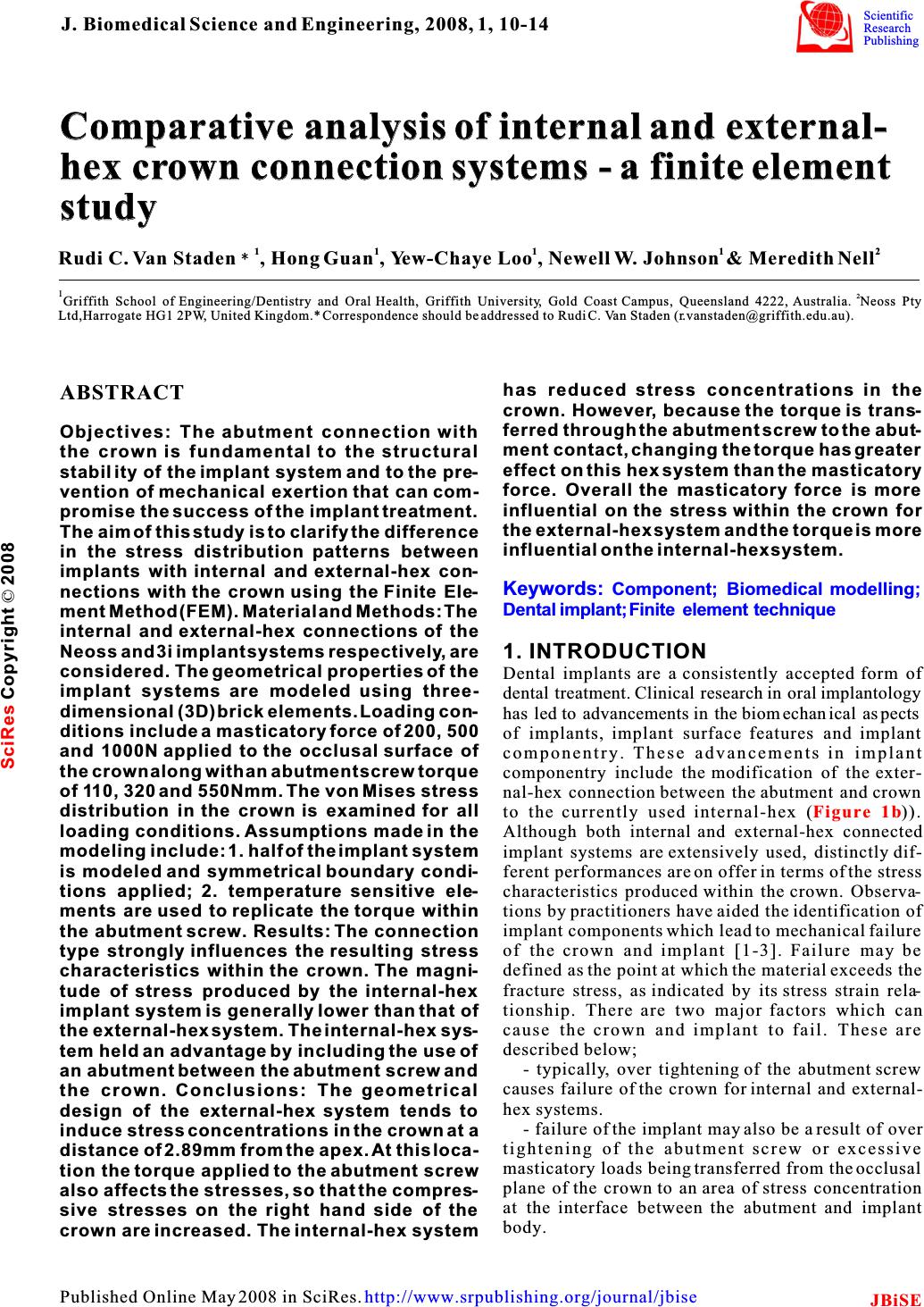 Comparative analysis of internal and external- hex crown connection systems - a finite element study Comparative analysis of internal and external- hex crown connection systems - a finite element study 1111 2 Rudi C. Van Staden, Hong Guan , Yew-Chaye Loo, Newell W. Johnson& Meredith Nell 12 Griffith School of Engineering/Dentistry and Oral Health, Griffith University, Gold Coast Campus, Queensland 4222, Australia. Neoss Pty Ltd,Harrogate HG1 2PW, United Kingdom.* Correspondence should be addressed to Rudi C. Van Staden (r.vanstaden@griffith.edu.au). has reduced stress concentrations in the ABSTRACT crown. However, because the torque is trans- ferred through the abutment screw to the abut- Objectives: The abutment connection with ment contact, changing the torque has greater the crown is fundamental to the structural effect on this hex system than the masticatory stability of the implant system and to the pre- force. Overall the masticatory force is more vention of mechanical exertion that can com- influential on the stress within the crown for promise the success of the implant treatment. the external-hex system and the torque is more The aim of this study is to clarify the difference influential on the internal-hex system. in the stress distribution patterns between implants with internal and external-hex con- nections with the crown using the Finite Ele- ment Method (FEM). Material and Methods: The internal and external-hex connections of the Neoss and 3i implant systems respectively, are1. INTRODUCTION considered. The geometrical properties of theDental implants are a consistently accepted form of implant systems are modeled using three-dental treatment. Clinical research in oral implantology dimensional (3D) brick elements. Loading con-has led to advancements in the biomechanical aspects ditions include a masticatory force of 200, 500of implants, implant surface features and implant and 1000N applied to the occlusal surface ofcomponentry. These advancements in implant the crown along with an abutment screw torquecomponentry include the modification of the exter- of 110, 320 and 550Nmm. The von Mises stressnal-hex connection between the abutment and crown distribution in the crown is examined for allto the currently used internal-hex ()). loading conditions. Assumptions made in theAlthough both internal and external-hex connected modeling include: 1. half of the implant systemimplant systems are extensively used, distinctly dif- is modeled and symmetrical boundary condi-ferent performances are on offer in terms of the stress tions applied; 2. temperature sensitive ele-characteristics produced within the crown. Observa- ments are used to replicate the torque withintions by practitioners have aided the identification of the abutment screw. Results: The connectionimplant components which lead to mechanical failure type strongly influences the resulting stressof the crown and implant [1-3]. Failure may be defined as the point at which the material exceeds the characteristics within the crown. The magni- fracture stress, as indicated by its stress strain rela- tude of stress produced by the internal-hex tionship. There are two major factors which can implant system is generally lower than that of cause the crown and implant to fail. These are the external-hex system. The internal-hex sys- described below; tem held an advantage by including the use of - typically, over tightening of the abutment screw an abutment between the abutment screw and causes failure of the crown for internal and external- the crown. Conclusions: The geometrical hex systems. design of the external-hex system tends to - failure of the implant may also be a result of over induce stress concentrations in the crown at a tightening of the abutment screw or excessive distance of 2.89mm from the apex. At this loca- masticatory loads being transferred from the occlusal tion the torque applied to the abutment screw plane of the crown to an area of stress concentration also affects the stresses, so that the compres- at the interface between the abutment and implant sive stresses on the right hand side of the body. crown are increased. The internal-hex system Keywords: Component; Biomedical modelling; Dental implant; Finite element technique Figure 1b J. Biomedical Science and Engineering, 2008, 1, 10-14Scientific Research Publishing JBiSE Published Online May 2008 in SciRes.http://www.srpublishing.org/journal/jbise SciRes Copyright ©2008 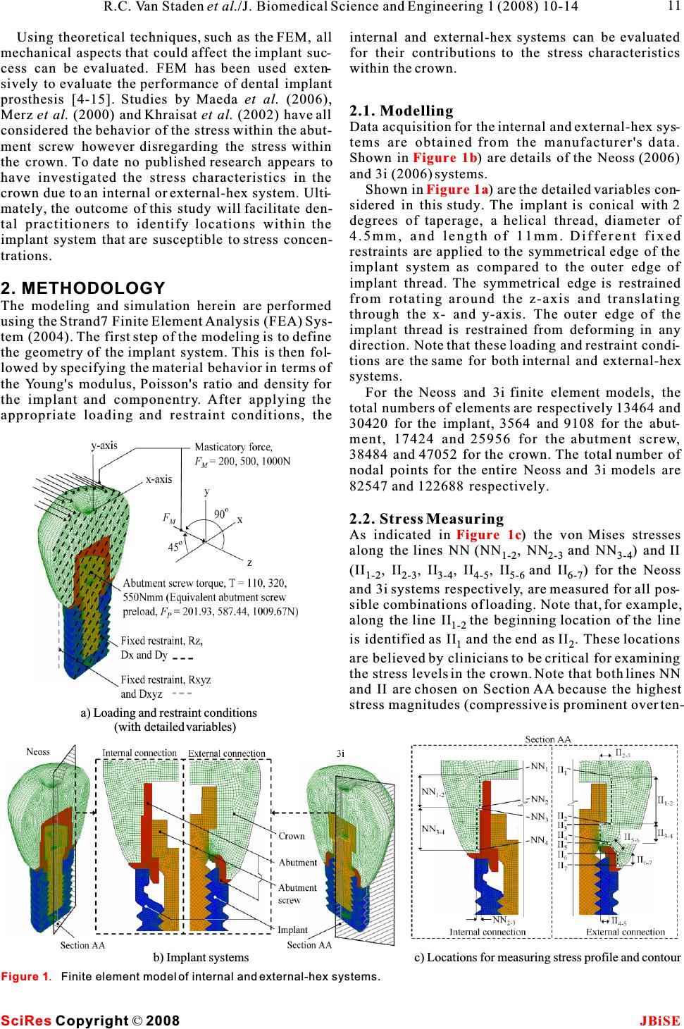 Using theoretical techniques, such as the FEM, all mechanical aspects that could affect the implant suc- cess can be evaluated. FEM has been used exten- sively to evaluate the performance of dental implant prosthesis [4-15]. Studies by Maeda et al. (2006), Merz et al. (2000) and Khraisat et al. (2002) have all considered the behavior of the stress within the abut- ment screw however disregarding the stress within the crown. To date no published research appears to have investigated the stress characteristics in the crown due to an internal or external-hex system. Ulti- mately, the outcome of this study will facilitate den- tal practitioners to identify locations within the implant system that are susceptible to stress concen- trations. 2. METHODOLOGY The modeling and simulation herein are performed using the Strand7 Finite Element Analysis (FEA) Sys- tem (2004). The first step of the modeling is to define the geometry of the implant system. This is then fol- lowed by specifying the material behavior in terms of the Young's modulus, Poisson's ratio and density for the implant and componentry.After applying the appropriate loading and restraint conditions, the c) Locations for measuring stress profile and contour a) Loading and restraint conditions (with detailed variables) Figure 1. Finite element model of internal and external-hex systems. internal and external-hex systems can be evaluated for their contributions to the stress characteristics within the crown. 2.1. Modelling Data acquisition for the internal and external-hex sys- tems are obtained from the manufacturer's data. Shown in ) are details of the Neoss (2006) and 3i (2006) systems. Shown in ) are the detailed variables con- sidered in this study. The implant is conical with 2 degrees of taperage, a helical thread, diameter of 4.5mm, and length of 11mm. Different fixed restraints are applied to the symmetrical edge of the implant system as compared to the outer edge of implant thread. The symmetrical edge is restrained from rotating around the z-axis and translating through the x- and y-axis. The outer edge of the implant thread is restrained from deforming in any direction. Note that these loading and restraint condi- tions are the same for both internal and external-hex systems. For the Neoss and 3i finite element models, the total numbers of elements are respectively 13464 and 30420 for the implant, 3564 and 9108 for the abut- ment, 17424 and 25956 for the abutment screw, 38484 and 47052 for the crown. The total number of nodal points for the entire Neoss and 3i models are 82547 and 122688 respectively. 2.2. Stress Measuring As indicated in) the von Mises stresses along the lines NN (NN, NNand NN) and II 1-22-3 3-4 (II, II, II, II, IIand II) for the Neoss 1-2 2-3 3-4 4-5 5-66-7 and 3i systems respectively, are measured for all pos- sible combinations of loading. Note that, for example, along the line IIthe beginning location of the line 1-2 is identified as II and the end as II. These locations 12 are believed by clinicians to be critical for examining the stress levels in the crown. Note that both lines NN and II are chosen on Section AA because the highest stress magnitudes (compressive is prominent over ten- Figure 1b Figure 1a Figure 1c SciRes JBiSE Copyright ©2008 11 R.C. Van Staden et al./J. Biomedical Science and Engineering 1 (2008) 10-14 b) Implant systems 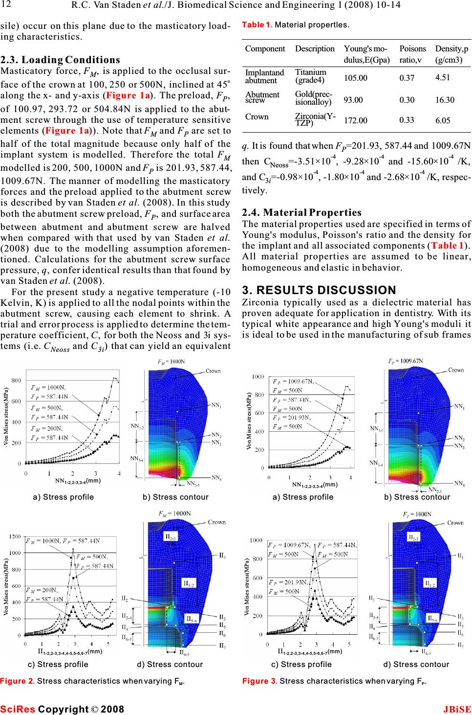 sile) occur on this plane due to the masticatory load- ing characteristics. 2.3. Loading Conditions Masticatory force, F, is applied to the occlusal sur- M o face of the crown at 100, 250 or 500N, inclined at 45 along the x- and y-axis (). The preload, F, P of 100.97, 293.72 or 504.84N is applied to the abut- ment screw through the use of temperature sensitive elements ()). Note thatF and F are set to MP half of the total magnitude because only half of the implant system is modelled. Therefore the total FM modelled is 200, 500, 1000N andF is 201.93, 587.44, P 1009.67N. The manner of modelling the masticatory forces and the preload applied to the abutment screw is described by van Staden et al. (2008). In this study both the abutment screw preload, F, and surface area P between abutment and abutment screw are halved when compared with that used by van Staden et al. (2008) due to the modelling assumption aforemen- tioned. Calculations for the abutment screw surface pressure, q, confer identical results than that found by van Staden et al. (2008). For the present study a negative temperature (-10 Kelvin, K) is applied to all the nodal points within the abutment screw, causing each element to shrink. A trial and error process is applied to determine the tem- perature coefficient,C, for both the Neoss and 3i sys- tems (i.e. C and C) that can yield an equivalent Neoss 3i Figure 1a Figure 1a Figure 2. Stress characteristics when varying F. MFigure 3.Stress characteristics when varying F. P a) Stress profileb) Stress contour c) Stress profiled) Stress contour a) Stress profileb) Stress contour c) Stress profiled) Stress contour q. It is found that when F=201.93, 587.44 and 1009.67N P -4 -4-4 then C=-3.51×10 , -9.28×10 and -15.60×10 /K, Neoss -4 -4-4 and C=-0.98×10, -1.80×10 and -2.68×10 /K, respec- 3i tively. 2.4. Material Properties The material properties used are specified in terms of Young's modulus, Poisson's ratio and the density for the implant and all associated components (). All material properties are assumed to be linear, homogeneous and elastic in behavior. 3. RESULTS DISCUSSION Zirconia typically used as a dielectric material has proven adequate for application in dentistry. With its typical white appearance and high Young's moduli it is ideal to be used in the manufacturing of sub frames Table 1 Table 1. Material propertles. Component Implantand abutment Abutment screw Crown Description Titanium (grade4) Gold(prec- isionalloy) Zirconia(Y- TZP) Young's mo- dulus, E (Gpa) 105.00 93.00 172.00 Poisons ratio, v 0.37 0.30 0.33 Density, p (g/cm3) 4.51 16.30 6.05 SciRes JBiSE Copyright ©2008 12 R.C. Van Staden et al./J. Biomedical Science and Engineering 1 (2008) 10-14 Von Mises stress(MPa)Von Mises stress(MPa) Von Mises stress(MPa) Von Mises stress(MPa) NN (mm) 1-2,2-3,3-4 II (mm) 1-2,2-3,3-4,4-5,5-6,6-7 II (mm) 1-2,2-3,3-4,4-5,5-6,6-7 NN (mm) 1-2,2-3,3-4 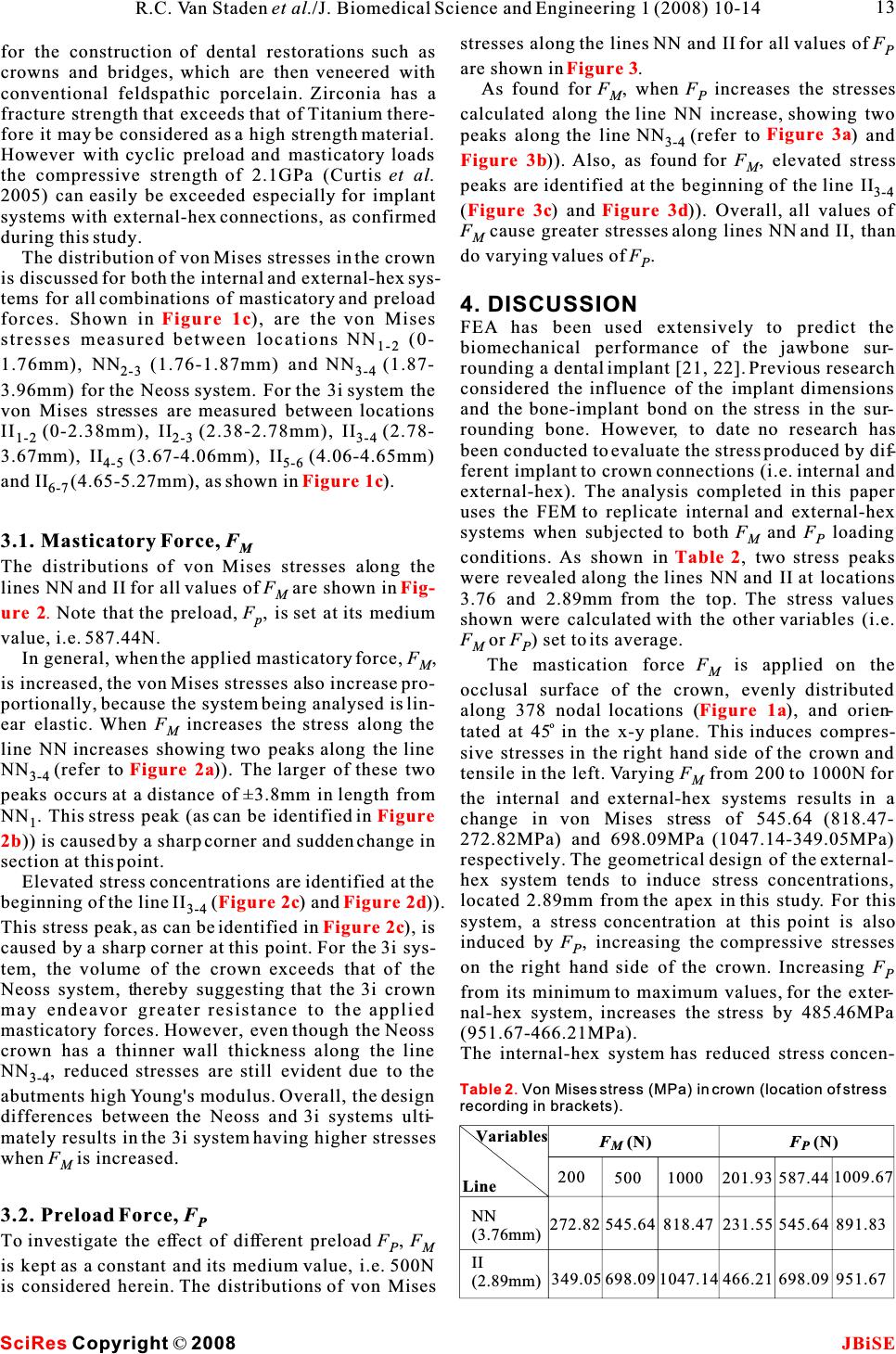 stresses along the lines NN and II for all values ofFP for the construction of dental restorations such as are shown in. crowns and bridges, which are then veneered with As found forF, when F increases the stresses conventional feldspathic porcelain. Zirconia has aMP fracture strength that exceeds that of Titanium there-calculated along the line NN increase, showing two fore it may be considered as a high strength material. peaks along the line NN(refer to) and 3-4 However with cyclic preload and masticatory loads )).Also, as found for F, elevated stress M the compressive strength of 2.1GPa (Curtiset al.peaks are identified at the beginning of the line II3-4 2005) can easily be exceeded especially for implant() and)). Overall, all values of systems with external-hex connections, as confirmedF cause greater stresses along lines NN and II, than M during this study. do varying values ofF. The distribution of von Mises stresses in the crownP is discussed for both the internal and external-hex sys- tems for all combinations of masticatory and preload 4. DISCUSSION forces. Shown in), are the von Mises FEA has been used extensively to predict the stresses measured between locations NN (0- 1-2 biomechanical performance of the jawbone sur- 1.76mm), NN (1.76-1.87mm) and NN(1.87-rounding a dental implant [21, 22]. Previous research 2-3 3-4 considered the influence of the implant dimensions 3.96mm) for the Neoss system. For the 3i system the and the bone-implant bond on the stress in the sur- von Mises stresses are measured between locations rounding bone. However, to date no research has II(0-2.38mm), II(2.38-2.78mm), II(2.78- 1-22-33-4 been conducted to evaluate the stress produced by dif- 3.67mm), II(3.67-4.06mm), II(4.06-4.65mm) 4-55-6 ferent implant to crown connections (i.e. internal and and II(4.65-5.27mm), as shown in ). 6-7 external-hex). The analysis completed in this paper uses the FEM to replicate internal and external-hex systems when subjected to both Fand F loading MP 3.1. Masticatory Force, FMconditions.As shown in, two stress peaks The distributions of von Mises stresses along thewere revealed along the lines NN and II at locations lines NN and II for all values ofF are shown in M3.76 and 2.89mm from the top. The stress values Note that the preload,F, is set at its medium pshown were calculated with the other variables (i.e. value, i.e. 587.44N. F or F) set to its average. MP In general, when the applied masticatory force, F, MThe mastication forceF is applied on the M is increased, the von Mises stresses also increase pro-occlusal surface of the crown, evenly distributed portionally, because the system being analysed is lin-along 378 nodal locations (), and orien- o ear elastic. WhenF increases the stress along the Mtated at 45 in the x-y plane. This induces compres- line NN increases showing two peaks along the line sive stresses in the right hand side of the crown and NN(refer to )). The larger of these two tensile in the left. VaryingFfrom 200 to 1000N for 3-4 M peaks occurs at a distance of±3.8mm in length fromthe internal and external-hex systems results in a NN. This stress peak (as can be identified in change in von Mises stress of 545.64 (818.47- 1 272.82MPa) and 698.09MPa (1047.14-349.05MPa) )) is caused by a sharp corner and sudden change in respectively. The geometrical design of the external- section at this point. hex system tends to induce stress concentrations, Elevated stress concentrations are identified at the located 2.89mm from the apex in this study. For this beginning of the line II () and)). 3-4 system, a stress concentration at this point is also This stress peak, as can be identified in ), is induced byF, increasing the compressive stresses P caused by a sharp corner at this point. For the 3i sys- on the right hand side of the crown. Increasing F tem, the volume of the crown exceeds that of theP Neoss system, thereby suggesting that the 3i crownfrom its minimum to maximum values, for the exter- may endeavor greater resistance to the applied nal-hex system, increases the stress by 485.46MPa masticatory forces. However, even though the Neoss (951.67-466.21MPa). crown has a thinner wall thickness along the line The internal-hex system has reduced stress concen- NN, reduced stresses are still evident due to the 3-4 abutments high Young's modulus. Overall, the design differences between the Neoss and 3i systems ulti- mately results in the 3i system having higher stresses when F is increased. M 3.2. Preload Force, FP To investigate the effect of different preload F,F PM is kept as a constant and its medium value, i.e. 500N is considered herein. The distributions of von Mises Figure 3 Figure 3a Figure 3b Figure 3cFigure 3d Figure 1c Figure 1c Table 2 Fig- ure 2. Figure 1a Figure 2a Figure 2b Figure 2cFigure 2d Figure 2c SciRes JBiSE Copyright ©2008 Table 2. Von Mises stress (MPa) in crown (location of stress recording in brackets). Variables Line NN (3.76mm) II (2.89mm) F(N) F(N) MP 200 272.82 349.05 500 545.64 698.09 1000 818.47 1047.14 201.93 231.55 466.21 587.44 545.64 698.09 1009.67 891.83 951.67 13 R.C. Van Staden et al./J. Biomedical Science and Engineering 1 (2008) 10-14  Clinical Implant Dentistry and Related Research 2005, trations, demonstrating that this design is less sus-7(4):221-228. ceptible to stress concentrations within the crown. [7]F. H. G. Butz, M. Okutan & J. R. Strub. Survival rate, fracture However, because of the transfer of the preloadstrength and failure mode of ceramic implant abutments after through the abutment screw to abutment contact, chewing simulation. Journal of Oral Rehabilitation 2005, 32(11):838-843. changing F is more influential on this hex system P[8]K. J. Anusavice & P. H. Dehoff. Influence of metal thickness on than F. Overall Fis more influential on the stressstress distribution in metal-ceramic crowns. Journal of Dental MM Research 1986, 65(9):1173-1178. within the crown for the external-hex system andFP[9]K. J. Anusavice. Stress distribution in metal-ceramic crowns is more influential on the internal-hex system.with a facial porcelain margin. Journal of Dental Research 1987, 66(9):1493-1498. [10]K. J. Anusavice. Influence of incisal length of ceramic and 5. CONCLUSIONloading orientation on stress distribution in ceramic crowns. Journal of Dental Research 1988, 67(11):1371-1375. This research is a pilot study aimed at offering an ini- [11]H.Y. Suzuki. Finite element stress analysis of ceramics crown tial understanding of the stress distribution charac-on premolar. Relation between ceramics materials and abut- teristics in the crown under different loading condi-ment materials. Nippon Hotetsu Shika Gakkai Zasshi 1989, tions. Realistic geometries, material properties, load-33(2):283-293. [12]T. Hino. A mechanical study on new ceramic crowns and ing and support conditions for the implant system bridges for clinical use. Osaka Daigaku Shigaku Zasshi 1990, were considered in this study. The geometrical design 35(1):240-267. of the external-hex system tends to induce stress con-[13]Zhang, B. & Wang , H. Three-dimensional finite element anal- centrations in the crown at a distance of 2.89mm fromysis of all-ceramic crowns of the posterior teeth. Hua Xi Yi Ke Da Xue Xue Bao 2000, 31(2):147-148. the apex. At this location,F also affects the stresses, P[14]K. A. Proos, J. Ironside & G. P. Steven. Finite element analysis so that the compressive stresses on the right hand sidestudies of an all-ceramic crown on a first premolar. Interna- of the crown are increased. The internal-hex systemtionalJournal of Prosthodontics2002, 15(4):404-412. [15]A. Imanishi, T. Ohyama & T. Nakamura. 3-D Finite element has reduced stress concentrations in the crown. How- analysis of all-ceramic posterior crowns. Journal of Oral ever, because the preload is transferred through theRehabilitation 2003, 30(8):818-822. abutment screw to the abutment contact, changing FP[16]Strand7 Pty Ltd.Strand7 Theoretical Manual 2004. Sydney, Australia. has greater effect on this hex system thanF. Overall M[17]Neoss Pty Ltd,Neoss Implant System Surgical Guidelines Fis more influential on the stress within the crown M2006. United Kingdom. th [18]http://www.3i-online.com.htm (accessed 12 July 2006). for the external-hex system and Fis more influen- P[19]R. C. van Staden, H. Guan, Y. C. Loo, N. W. Johnson & N. tial on the internal-hex system.Meredith. Stress Evaluation of Dental Implant Wall Thickness Future recommendations include the evaluation using Numerical Techniques.Applied Osseointegration Research 2008, (In Press). of other implant variables such as the implant wall[20]A. R. Curtis, A. J. Wright & G. J. Fleming. The influence of thickness and thread design. Ultimately, all implantsimulated masticatory loading regimes on the bi-axial flexure components can be understood in terms of their influ-strength and reliability of a Y-TZP dental ceramic. Journal of ence on the stress produced within the implant itself.Dentistry 2005, 34(5):317-325. [21]D. H. DeTolla, S. Andreana, A. Patra, R. Buhite & B. Comella. Role of the finite element model in dental implants.Journal of Oral Implantology 2000, 26(2):77-81. [22]J. P. Geng, K. B. Tan & G. R. Liu. Application of finite element ACKNOWLEDGEMENTS analysis in implant dentistry: a review of the literature.Jour- This work was made possible by the collaborative support from nal of Prosthetic Dentistry 2001, 85(6):585-598. griffith's school of engineering and school of dentistry and oral health. A special thank you goes to messer john divitini and fredrik engman from neoss pty ltd for their continual contribution. REFERENCE [1]Y. Maeda, T. Satoh & M. Sogo. In vitro differences of stress con- centrations for internal and external hex implantabutment con- nections: a short communication. Journal of Oral Rehabilita- tion 2006, 33:75-78. [2]B. R. Merz, S. Hunenbart & U. C. Belser. Mechanics of the implantabutment connection: an 8-degree taper compared to a butt joint connection.International Journal of Oral and Maxillofacial Implants 2000, 15:519-526. [3]A. Khraisat, R. Stegaroiu, S. Nomura & O. Miyakawa. Fatigue resistance of two implant/abutment joint designs.Journal of Prosthetic Dentistry2002, 88:604-610. [4]S. Capodiferro, G. Favia, M. Scivetti, G. De Frenza & R. Grassi. Clinical management and microscopic characterisation of fatique-induced failure of a dental implant.Case report. Head and Face Medicine 2006, 22, 2:18. [5]P. Gehrke, G. Dhom, J. Brunner, D. Wolf, M. Degidi & A. Piattelli. Zirconium implant abutments: fracture strength and influence of cyclic loading on retaining-screw loosening.Quin- tessence International 2006, 37, 1:19-26. [6]A. Khraisat. Stability of implant-abutment interface with a hexa- gon-mediated butt joint: failure mode and bending resistance. SciRes JBiSE Copyright ©2008 14 R.C. Van Staden et al./J. Biomedical Science and Engineering 1 (2008) 10-14 |