International Journal of Communications, Network and System Sciences
Vol.09 No.11(2016), Article ID:72222,10 pages
10.4236/ijcns.2016.911042
Fixed Point Iteration Chaos Controlled ZCDPLL
Qassim Nasir
Electrical and Computer Engineering Department, University of Sharjah, Sharjah, UAE

Copyright © 2016 by author and Scientific Research Publishing Inc.
This work is licensed under the Creative Commons Attribution International License (CC BY 4.0).
http://creativecommons.org/licenses/by/4.0/


Received: September 26, 2016; Accepted: November 21, 2016; Published: November 24, 2016
ABSTRACT
The stable operation of first and second order Zero Crossing Digital Phase Locked Loop (ZCDPLL) is extended by using a Fixed Point Iteration (FPI) method with relaxation. The non-linear components of ZCDPLL such as sampler phase detector and Digital Controlled Oscillator (DCO) lead to unstable and chaotic operation when the filter gains are high. FPI will be used to stabilize the chaotic operation and consequently extend the lock range of the loop. The proposed stabilized loop can work in higher filter gains which are needed for faster signal acquisition.
Keywords:
Non-Uniform Sampling, Digital Phase Locked Loops, Zero Crossing DPLL, Chaos Control

1. Introduction
Digital Phase Locked Loop (PLL) has been widely used and for many years in wireless and wired communications subsystems. It is an essential component in clock and carrier recovery, and frequency synthesizer. Digital Phase locked Loops (DPLLs) have better reliability and higher stability compared to analogue counterpart at lower cost and can easily be part of a digital processing equipment [1] . The researchers show strong interest in the design of digital PLLs (DPLLs) to solve problems associated with analog DPLLS, such as, sensitivity to DC drift and component inaccuracies and saturation, and their need for initial calibration [1] [2] . The sampler type classifies DPLL into two major categories: uniform sampling DPLLs (US-DPLLs) and non-uniform sampling DPLLs (NUS-DPLLs). Different types of NUS-DPLLs have been introduced according to the way to detect the phase difference between locally generated carrier and the input signal to the loop from the sampled signal such as zero crossing DPLL (ZCDPLL) [3] [4] and digital tan-lock loop (DTLL) [5] [6] [7] . ZCDPLL is a closed loop system used to follow the zero crossing of the input carrier signal. It consists of a sampler (acting as a phase detector), a digital loop filter and a digital controlled oscillator [8] [9] [10] [11] . The most commonly used DPLL is the Zero Crossing Digital Phase Locked Loop (ZCDPLL). The operation is based on tracking the signal input phase by using non uniform sampling techniques. The sample value is a function of the signal input phase. These values are filtered before they are used back to control the next sampling time by the help of Digital Controlled Oscillator (DCO). The non-linear behaviour of ZCDPLL leads bifurcation instabilities to its path to chaos [12] .
A number of methods were proposed for chaos control [13] such as using Pyragas method to broaden the tracking range by extending the stable operation behaviour of ZCDPLL to a larger digital filter gain, which leads to larger input frequency [11] . Fixed Point Iteration (FPI) with relaxation will be presented to extend the stable operation range of both first and second order ZCDPLL. The stabilized loops are analyzed and the results are verified using bifurcation theory and a numerical simulation. It is the first time that FPI used to stabilize the chaotic operation of the DPLL.
In Section 2, the conventional first order ZCDPLL operation is described. Section 3 discusses the Fixed Point stabilization algorithm, and in section 4 the second order ZCDPLL is presented, while Section 5 details the operation of the second order ZCDPLL when FPI chaos control is included in the loop. Simulation results are presented in Section 6 and finally conclusions are given in Section 7.
2. First Order ZCDPLL
Conventional first order ZCDPLL is shown in Figure 1. Let us assume that the input signal  is defined as

 (1)
(1)
where  is Additive White Gaussian Noise (AWGN),
  is initial phase (can be assume zero without loosing generality),
  is the input signal frequency, and
  is the nominal frequency or DCO free running frequency when no input signal is applied. The input signal is assumed to be noise free [
 ]. This input signal
  is sampled at
  instants determined by DCO.
 (2)
(2)
the sampling instants  can be represented by

Figure 1. Block diagram of conventional first ZCDPLL.
 (3)
(3)
 is the Digital Controlled Oscillator (DCO) period, which is given by [15] :
 (4)
(4)
where  is the nominal period,
  is the output of digital filter. The input signal phase can be represented as
 . The sampled signal input
  will be
 . (5)
. (5)
The phase error  is determined by:
 . (6)
. (6)
Then
 . (7)
. (7)
The sampled values  is passed through a digital filter D(z) to produce the output
 . The digital loop filter can be of zero order (just gain block) or first order (gain and summation blocks). The loop filter output
  can be written as:

where K is the zero order filter gain (First Order ZCDPLL), while for first order filter or second order ZCDPLL, the outputs will be:
 (8)
(8)
where  and
and  are the loop filter gains. If a frequency step of a value
  is applied to the ZCDPLL (
 ), then the signal input phase can be expressed as:


 (9)
(9)
where  is normalized frequency step size. Consequently the phase error can be written as

 . (10)
Therefore first order ZCDPLL phase error operation function will be:
 . (11)
The phase error mapping function ( ) will be:
 . (12)
3. Extending the Stable Operation of First Order ZCDPLL
Various methods and techniques were used to control the instability of chaotic operation of control loop such as Ott-Grebogi-Yorke (OGY) or Pyragas [14] . In this paper the Fixed Point Iteration (FPI) with relaxation is used to extend the stable operation of the ZCDPLL. FPI was used the first time by Babylonian (2000 B.C) to estimate the square root. The original version was used for finding  as:
as:
 . (13)
Then Hillam [16] proposed FPI with relaxation for fixed point stability as follow:
 (14)
(14)
p is fractional constant which control the amount of feedback. This algorithm can’t be used when  (non-hyperbolic fixed points (8, 9). Let us apply the above FPI with relaxation to stabilize ZCDPLL operation. Then the operation Equation (12) should become as:

 . (15)
The system will be stable when . This condition of the derivative of Equation (15) will be:

where . The stable operation phase error (
 ) was found to be at
  [15] . The values of the constant (p) which can stabilize ZCDPLL operation is determined from Equation (16). The values are

The stabilized first order ZCDPLL using FPI with relaxation is shown in Figure 2.
4. Second Order ZCDPLL Operation
The first order filter transfer function  of the second order ZCDPLL can be written as:

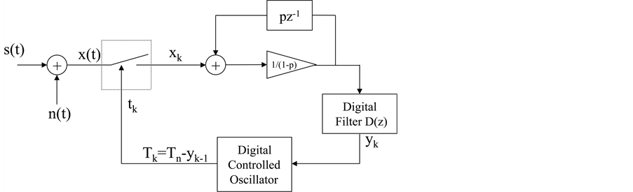
Figure 2. FPI chaos controlled first order ZCDPLL.
Then  is expressed as
 (16)
(16)
 . (17)
To express Equation (16) in time domain:

Then the operation Equations (10) is given by [17]
 (18)
(18)
 (19)
(19)
If we assume ,
,  , then the second order ZCDPLL operation equation can be written as
 (20)
(20)
To guarantee the stable operation of the loop, then inequality should be satisfied [17]
 (21)
(21)
5. Extending the Stable Operation of Second Order ZCDPLL
The proposed FPI with relaxation for fixed point stability is applied for second order as well and the new operation equation can be written as:
 (22)
(22)
The system state vector is defined as ,
,  ,
, . Then
 (23)
(23)
around the stable operating point ,
, . The Jacobian
  is given by
 (24)
(24)
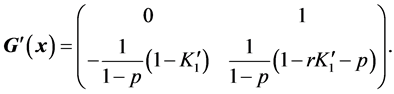
In order to have eigen values of  less than 1, or
 , where
  satisfies the characteristic equation
  in [17]
 (25)
(25)
Using Jury stability test [18] , the roots of the polynomial  defined in (25) are within a unit circle, or the eigen values are less than 1, if
  greater than 0. Then p should satisfies the following:


 (26)
(26)
Since  or
or  this leads that
 . Jury stability test ap-
plied on  the absolute value of the constant term of the equation should be less than 1. This leads to


 (27)
(27)
6. System Performance
The first and second order conventional and FPI chaos controlled ZCDPLL is simulated by using MATLAB. The input signal is assumed to be  with peak amplitude of 1 volt and angular frequency of
 . The free running fre-
quency of DCO is  or
or . During simulation, the first 100 samples of the DCO period (
 ) values are discarded to allow the loop to stabilize. The next 100,000 samples are collected and recorded to generate bifurcation plot. The bifurcation plot maps the
  values versus the filter gain(s). It will be used to compare the operation ranges of the conventional and FPI chaos controlled ZCDPLL.
First order ZCDPLL is subjected to a frequency step of 1.3 Hz. Then  values are recorded for three cases. The first case shown in Figure 3(a) is for conventional ZCDPLL. The conventional loop bifurcates at
 . DCO period jitter is used to show the amount of deviation of the period compared to the input signal period (jitter
= , where T is input signal period). Figure 3(b) shows that FPI chaos
controlled first order ZCDPLL bifurcates , which is higher than for conventional loop (Chaos control constant
  was used in this test). This agrees with the theoretical analysis presented earlier. Figure 3(c) shows how adaptive values of the constant (p) (Equation (16)) can be used to continuously stabilize the loop by changing its values according to filter gain (
 ).
).
There are two filter parameters in the second order loop ( ). In these simulations we fixed the gains ratio (
 ) and vary
  value. Figure 4 shows clearly
that the FPI chaos controlled loop has extended stable operation when the filter parameter ( ) varied. Gains ratio used here is
 , and the chaos control constant is set to be (
 ). The conventional ZCDPLL bifurcates at
  while the FPI chaos controlled loop bifurcate after
 . Figure 5 shows that even the filter gains ration (r) is increased to 1.6, that the loop still has extended operation range as well. The conventional loop bifurcates at
 , while the FPI chaos controlled loop starts to bifurcate at
 . If the filter gains ratio r is further increased as shown in Figure 6, the FPI chaos controlled will be unstable. This means that the chaos control constant (p) should be carefully chosen according to the inequality that is derived in this paper.
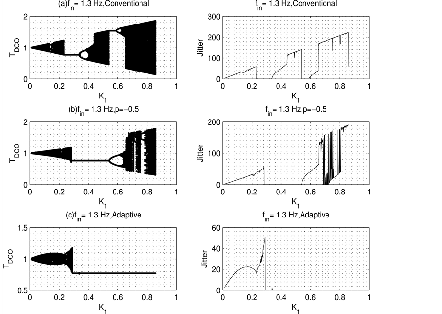
Figure 3. First order FPI-ZCDPLL performance for different values of p.

Figure 4. Second order FPI-ZCDPLL performance for different values of p and .
.
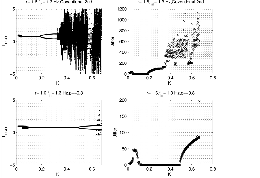
Figure 5. Second order FPI-ZCDPLL performance for different values of p and .
.
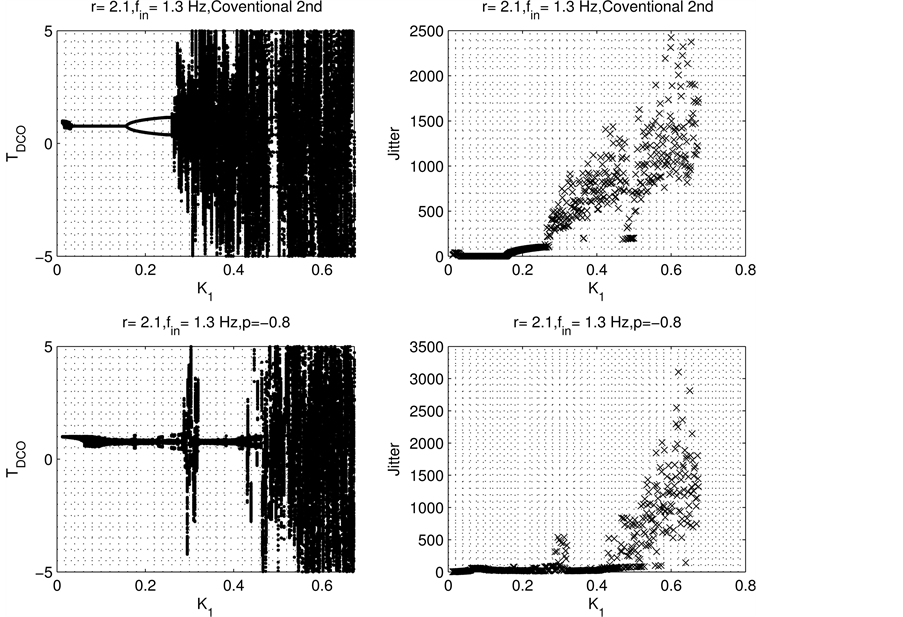
Figure 6. Second order FPI-ZCDPLL performance for different values of p and .
.
7. Conclusion
This paper proposes a Fixed Point Iteration (FPI) with relaxation to control the chaotic operation of the ZCDPLL. The analytic expressions for the stable operation for both conventional and FPI chaos control first and second order ZCPLL are found and confirmed by simulation. It is found that the lock range of the FPI chaos controlled loop is larger than that of the conventional loop for both orders. The validity of the results is conformed through numerical simulations. It is also found that careful selection of chaos control parameters is needed to ensure that the loop is still working in stable operation. This extended operation of the ZCDPLL leads to larger lock range. The larger values of filter gains of FPI chaos controlled will automatically decrease the input signal acquisition time.
Cite this paper
Nasir, Q. (2016) Fixed Point Iteration Chaos Controlled ZCDPLL. Int. J. Communications, Network and System Sciences, 9, 535-544. http://dx.doi.org/10.4236/ijcns.2016.911042
References
- 1. Lindsay, W. and Chie, C.M. (1981) A Survey of Digital Phase Locked Loops. IEEE Proceeding, 69, 410-431.
http://dx.doi.org/10.1109/PROC.1981.11986 - 2. Al-Araji, S.R., Hussain, Z.M. and Al-Qutayri, M.A. (2006) Digital Phase Lock Loops: Architectures and Applications. Kluwer Academic Publishers (Springer), Netherlands.
http://dx.doi.org/10.1007/978-0-387-32864-5 - 3. Nasir, Q. (2015) FIR Digital Filter Based ZCDPLL for Carrier Recovery. International Journal of Electronics, 103, 736-746.
http://dx.doi.org/10.1080/00207217.2015.1046501 - 4. Nasir, Q. and Al-Araji, S. (2011) Linearized Phase Detector Zero Crossing DPLL Performance Evaluation in Faded Mobile Channels. Circuits and Systems, 2, 139-144.
http://dx.doi.org/10.4236/cs.2011.23021 - 5. Lee, J. and Un, C. (1982) Performance Analysis of Digital Tanlock Loop. IEEE Transactions on Communications, 30, 2398-2411.
http://dx.doi.org/10.1109/TCOM.1982.1095407 - 6. Hussain, Z.M. and Boashash, B. (2002) The Time-Delay Digital Tanlock Loop: Performance Analysis in Additive Gaussian Noise. Journal of the Franklin Institute, 339, 4360.
http://dx.doi.org/10.1016/S0016-0032(01)00059-X - 7. Sarkar, B.C., De Sarkar, S.S. and Banerjee, T. (2014) Nonlinear Dynamics of a Class of Digital Tan-Lock Loops with Non-Ideal Phase Detector. Signal Processing, 104, 311-318.
http://dx.doi.org/10.1016/j.sigpro.2014.04.008 - 8. Nasir, Q. and Al-Araji, S. (2009) Performance Analysis of Zero Crossing DPLL with Linearized Phase Detector. International Journal of Information and Communication Technology, 1.
- 9. Al-Araji, S., Mezher, K. and Nasir, Q. (2013) First-Order Digital Phase Lock Loop with Continuous Locking. 5th International Conference on Computational Intelligence, Communication Systems and Networks, Madrid, 5-7 June 2013, 414-417.
http://dx.doi.org/10.1109/cicsyn.2013.30 - 10. Nasir, Q. and Al-Araji, S. (2013) Performance Evaluation of Sigma Delta Zero Crossing DPLL. The IEEE International Conference on Electronics, Circuits, and Systems, 11-14 December 2011, Beirut.
- 11. Nasir, Q. (2005) Extended Lock Range Zero-Crossing Digital Phase-Locked Loop with Time Delay. EURASIP Journal on Wireless Communications and Networking EURASIP JWCN, 3, 413-418.
http://dx.doi.org/10.1155/wcn.2005.413 - 12. Nasir, Q. (2004) Chaotic Behaviour of First Order Zero Crossing Digital Phase Locked Loop. IEEE Asia-Pacific Conference on Circuits and Systems, 977-980.
http://dx.doi.org/10.1109/apccas.2004.1413044 - 13. Fradkov, A.L. and Evans, R.E. (2002) Control of Chaos: Survey 1997-2000. Proceedings of 15th IFAC World Congress, Barcelona.
http://dx.doi.org/10.3182/20020721-6-es-1901.01645 - 14. Pyragas, K. (1992) Continuous Control of Chaos by Self-Controlling Feedback. Physical Letters A, 170, 412-428.
http://dx.doi.org/10.1016/0375-9601(92)90745-8 - 15. Osborne, H.C. (1980) Stability Analysis of an Nth Power Phase-Locked Loop-Part I: First Order DPLL. IEEE Transactions on Communications, 28, 1343-1354.
http://dx.doi.org/10.1109/TCOM.1980.1094771 - 16. Hillam, B. (1975) A Generalization of Kransnoselki’s Theorem on the Real Line. Mathematics Magazine, 48, 167-168.
http://dx.doi.org/10.2307/2689700 - 17. Osborne, H.C. (1980) Stability Analysis of an Nth Power Phase-Locked Loop-Part II: Second- and Third-Order DPLLs. IEEE Transactions on Communications, 28, 1355-1364.
http://dx.doi.org/10.1109/TCOM.1980.1094772 - 18. Kuo, B.C. (1963) Analysis and Synthesis of Sampled Data Control Systems. Prentice Hall, Englewood Cliffs.