Journal of Software Engineering and Applications
Vol. 5 No. 5 (2012) , Article ID: 19447 , 3 pages DOI:10.4236/jsea.2012.55042
Flex Sensor Based Robotic Arm Controller Using Micro Controller
![]()
1Department of Electronics and Communication, BLDEA College of Engg Bijapur-3, India; 2Department of Electronics and Communication, KBN College of Engg Gulbarga-4, India.
Email: abidsyed4u@gmail.com
Received September 6th, 2011; revised March 10th, 2012; accepted April 3rd, 2012
Keywords: Flexsensors; ADC; Data Glove (DG); Micro Contoller; Position Control; DOF (Degree of Freedom)
ABSTRACT
Sensor plays an important role in robotics. Sensors are used to determine the current state of the system. Robotic applications demand sensors with high degrees of repeatability, precision, and reliability. Flex sensor is such a device, which accomplish the above task with great degree of accuracy. The pick and place operation of the robotics arm can be efficiently controlled using micro controller programming. This designed work is an educational based concept as robotic control is an exciting and high challenge research work in recent year.
1. Introduction
The ever increasing population trend of the new millennium expects new technical innovation to meet the new challenges being faced by human beings. The integration of medical science and engineering has made the task like complicated surgery by robotic arm simpler. To capture the motion of human limbs, sensors can be used. Some companies have designed units, which can integrate accelerometers, gyroscopes, magnetometers and can be attached to human limbs. These units can be worn for video game character modelling [1], virtual reality [2,3], activity recognition [4]. A sensor is a device that can measure some attribute of motion, being one of the three primitives of robotics (besides planning and control), sensing plays an important role in robotic paradigms. Robotic arm manipulators can have different configurations and kinematic constraints. Few of these constraints can be effectively mapped from the human arm domain to the robot’s restricted joint space. In this paper a general method of mapping human motions to the robotic arm domain has been demonstrated. The arm moment is reciprocated almost exactly by the robotic arm. Data capture is achieved with the special motion capture sensor called “Shape Tape” that is worn by the human operator. Any human arm (or even leg, neck or spine) moment can be mapped on to any of the robotic arm manipulator. Below is the outline of this paper.
Section 2 describes related work, which gives a detail discussion about the various works that are taking place in this field. Section 3 describes the data hand glove controller and micro controller used. Section 4 shows the flow of action in the presented work. Section 5 discusses results. Finally Section 6 discusses about conclusion and future work.
2. Related Work
An interesting description of inertial sensors and some innovative application of sensors have been discussed in [1]. [2] gives an examination of the impact of individual sensor on the performance of a navigation system. [5] gives the design of a controller intended for teleoperation, which is capable of controlling an anthropomorphic robotic arm through a LAN or via the Internet. [6] provides a review of relevant mobile robot positioning technologies like Odometry, Inertial Navigation, Magnetic Compasses, GPS Model Matching etc. Pick and place operation by controlling the speed and position using FPGA and sensor circuitry has been discussed in [7-8]. But the important contribution of present work is that any human arm moments can be mapped onto the robotic arm with good precision. Further the flexibility of micro controller programming makes the task easier. Finally [9] discusses the robotic arm function using MATLAB simulink.
3. Flex Sensor Based Robotic Arm Using Micro Controller
The block diagram consist of three important parts:The wearable data glove controller, Processing unit and the servo controlled robotic arm as shown in Figure 1. The DG has been designed with two flex sensors, signal con-
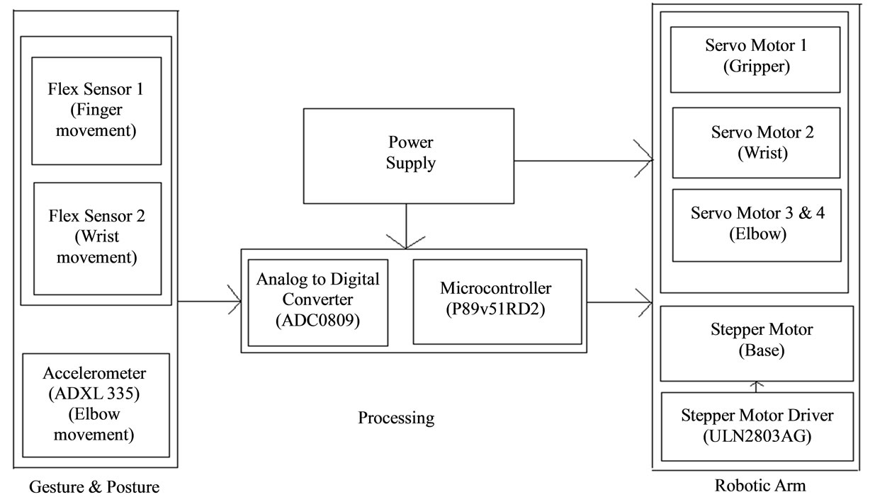
Figure 1. Flex sensor based robotic arm using micro controller.
ditioning circuit and 3-axis accelerometer. Processing unit consists of micro controller (P89V51RD2), analog to digital converter (ADC0809), stepper motor driver (ULN 2803AG). At other side a 3 degree of freedom robotic arm is built using 4 servomotors and one stepper motor. Experimental set-up is shown in Figure 2.
Flex Sensors
Flex sensors are analog resistors. These resistors work as variable analog voltage divider. Inside the flex sensor are carbon resistive elements with thin flexible substrate. More carbon means less resistance. When the substrate is bent the sensor produces resistance output relative to the bend radius. The flex sensor achieves great form-factor on a thin flexible substrate. When the substrate is bent, the sensor produces a resistance output correlated to the bend radius as shown in Figure 3. Smaller the radius, higher will be the resistance value [2].
The impedance buffer in the circuit is a single sided operational amplifier used with these sensors as shown in Figure 4. Since low bias current of the op amp reduces error due to source impedance of the flex sensor as voltage divider. The variation in deflection or bending of flex sensor results in variation of resistance itself. The signal conditioning circuit is used to read these resistance changes and it is given to ADC.
ADC converts these values into equivalent digital values.
Micro controller: The micro controller is responsible for controlling the action of robotic arm. It receives input variation of flex sensor through ADC, which is given in form of proportional current variation to motors attached to robotic arm. The design engineer can choose to run the application with the conventional 80C51 clock rate (12
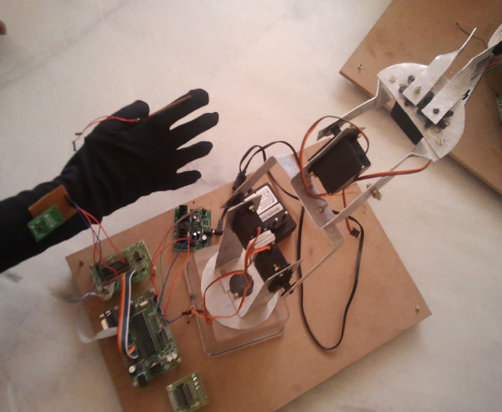
Figure 2. Experimental set-up.
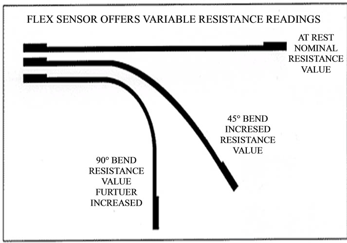
Figure 3. Flex sensor bend proportional to varying degree of resistance.
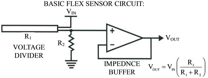
Figure 4. Flex sensor basic circuit.
clocks per machine cycle) or select the X2 mode (six clocks per machine cycle) to achieve twice the throughput at the same clock frequency [8].
4. Flow of Action for the Robotic Arm
• Read values of the sensor;
• Micro controller processes the sensor values;
• Send values from microcontoller to servomotors;
• Pick up the objects;
• Place at the required position;
• Bring arm at original position.
5. Results and Discussion
5.1. Flex Sensor Output Variation
Figure 5 shows the variation of volt with respect to variation in deflection of flex sensor. Initially the flex sensor is at default position, a constant value of 73 degree. The value decreases as we start bending the flex sensor. This particular change in flex sensor value is used to rotate servo motors.
5.2. Accelerometer Output Variation
Figure 6 shows the changes due to tilt of accelerometer in forward/backward(X axis), left/right (Y axis) and up/down (Z axis) direction. Accelerometer converts the deflections into equivalent voltage variation. ADC converts these analog voltage values into equivalent digital values. When there are positive deflections, motor rotates in clockwise direction and in counter-clockwise direction for negative values.
6. Conclusion and Future Work
The paper discussed a hardware and software co design of robotic arm controller using four servomotors employing micro controller. Micro controller programming can be done with an ease to suit the requirements. Unlike [7] which employ FPGA based control. Micro controller based programs can be flexibly modified to suit the necessary drive control of the serve motor.
Researcher can work for wireless control of the robotic arm by employing some wireless application protocol. Then the robotic arm can be more efficiently employed.
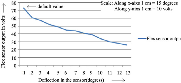
Figure 5. Deflection in the sensor V/S flex sensor output.
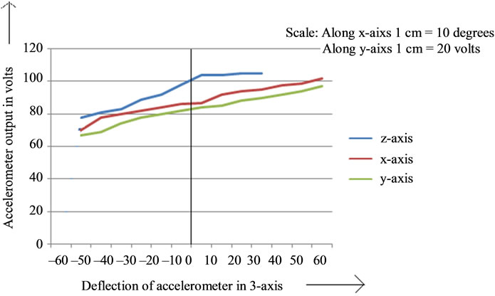
Figure 6. Deflection of accelerometer in 3 axis V/S accelerometer output.
The robotic arm can be fitted with wheel and more sensors to equip the device with more flexible movements of the robotic arm.
REFERENCES
- R. Slyper and J. Hodgins, “Action Capture with Accelerometers,” Euro Graphics/A CMSIG GRAPHS Symposium on Computer Animation, 2008.
- E. Foxl and L. Naimark, “Vis-Tracker: A Wearable Vision-Inertial Self-Tracker,” IEEE Virtual Reality Conference, 22-26 March 2003, Los Angeles.
- M. Gross and D. James, “Eurographics/ACM SIGGRAPH Symposium on Computer Animation,” Smart Objects Conference SOC ’03, Grenoble, 2003.
- L. Bio and S. Intille, “Activity Recognition from User-Annotated Acceleration Data,” Pervasive Computing, Vol. 3001, 2004, pp. 1-17. doi:10.1007/978-3-540-24646-6_1
- D. Fontaine, D. David and Y. Caritu, “Sourceless Human Body Motion Capture,” Smart Objects Conference (SOC 2003), Grenoble, 2003.
- J. Bernstein, H. R. Everett, L. Feng, and D. Wehe, “Mobile Robot Positioning Sensors & Techniques,” Journal of Robotic Systems, Special Issue on Mobile Robots, Vol. 14, No. 4, pp. 231-249.
- U. D. Meshram and R. Harkare, “FPGA Based Five Axis Robot Arm Controller,” International Journal of Electronics Engineering, Vol. 2, No. 1, 2010, pp. 209-211.
- http://en.wikipedia.org/wiki/80c51
- C. Edwards and E. Smith, “Design of Simulink-Based 2- DOF Robot Arm Control Workstation,” 31 October 2006.