Journal of Biomedical Science and Engineering
Vol.08 No.08(2015), Article ID:59212,10 pages
10.4236/jbise.2015.88051
Flexible Polyimide Microelectrodes Array for Transcorneal Electrical Stimulation
Luis Niño de-Rivera1, Fidel W. Pérez-Tovar1, Jorge Santiago Amaya1, Félix Gil Carrasco2
1Instituto Politécnico Nacional (IPN, México), ESIME UPC, México, México
2Asociación para evitar la ceguera en México, I.A.P., Hospital “Luis Sánchez Bulnes” (APEC), México, D.F., México
Email: luisninoderivera@gmail.com
Copyright © 2015 by authors and Scientific Research Publishing Inc.
This work is licensed under the Creative Commons Attribution International License (CC BY).
http://creativecommons.org/licenses/by/4.0/


Received 25 June 2015; accepted 24 August 2015; published 27 August 2015
ABSTRACT
The relationship between the parameters of Transcorneal Electrical Stimulation (TES) and its neuro-protective effect of TES on axotomised Retinal Ganglion Cells (RGCs) is still unclear. This work discusses the design strategy of a new non conventional TES stimulator, the micro fabrication processes and characterization of an array of MEMS microelectrodes over a flexible polymer layer substrate to stimulate the human cornea. The micro-array of electrodes, over a flexible smooth biocompatible polyimide substrate, fine tunes the curvature of the cornea. This tool can help researchers to define the optimal electric stimulation parameters required in TES.
Keywords:
Microelectrodes, Flexible Polymide Microelectrodes, Transcorneal Electrical stimulation

1. Introduction
Retinal degenerative diseases such as age-related macular degeneration (AMD), retinitis pigments (RP) and Glaucoma are a leading cause of blindness in adult. Transcorneal Electrical Stimulation (TES) has an effect on the survival of axotomised retinal ganglion cells and on phosphene sensation when the cornea is properly stimulated [1] . TES has demonstrated great potential in alleviating the problems and disabilities produced by these diseases [2] -[5] . However, the relationship between the parameters of TES and the neuro-protective effect of TES on axotomised Retinal Ganglion Cells (RGCs) or its effects on other retinal structures is still unclear [6] [7] . To have a better understanding of that relationship, a strategy is required to fire selected ganglion cells and other cell types [8] -[12] . We believe that this strategy supposes to stimulate with different stimulation parameters, as well as to evaluate the effect of a mixture of several stimulation waveforms. There are two ways in which ganglion cell spiking can be elicited: either through direct activation, where the electric stimulus acts directly on the ganglion cell, or through indirect activation, where presynaptic neurons are activated by the electric stimulus and this results in a modulation of synaptic input to the ganglion cell [13] .
TES is an indirect stimulation; then, we suggest that waveforms should be analogous to cone and rod response when exited by a spot of light. Then, non-conventional signal generator is required to be coupled to the cornea by a set of multi electrodes fitting the surface of the cornea. Currently, only two different corneal mono-polar electrodes are available in TES research: DTL-Plus and ERG-Jet. These two electrodes usually transmit only one single bipolar potential to the cornea [1] .
Researchers around the world have focused their attention on the creation of retinal prosthesis (RP) based on epi or subretinal chips that stimulate the retina by a multi electrodes array inside the ocular glove [14] -[16] . However, this procedure is highly invasive for the porpoise of testing different stimulation parameters. Important results in RP have been published; among others, we find that controlled electrical signals applied to a small area, inside the ocular glove, over the retina of a blind volunteer via microelectrodes array result in the perception of a small spot of light. For direct activation, over the surface of the retina, the total charge per pulse that is required to elicit a spike increases for larger diameter stimulating electrodes. Also, the total charge required to elicit a spike increases with pulse duration. Therefore, the use of short-duration pulses and small-diameter stimulating electrodes may be the most efficient way to elicit spiking through direct activation. Recent work suggests that outer retinal degeneration does not significantly affect the threshold for direct activation of the ganglion cell [17] -[19] . Retinal stimulation procedure inside ocular globe is the dominant strategy in RP; however, as said above it is an invasive procedure, which makes it difficult to study the effects of electrical stimulation, varying a great set of their parameters. TES is a non-invasive procedure that alternatively will help to study the effects of electrical stimulation in the visual system. TES applied over the surface of the cornea by a multi electrode array is a required tool that will help to find, among others, the optimal parameters of TES to be neuroprotective. Electrical stimulation over different places over the surface of the cornea, as well as electrical stimulation with different parameters, opens new research opportunities.
2. Methodology
Most reported research in TES [1] -[3] , both indirect and direct stimulation, uses simple bipolar square waveforms to target a complex neural network system at the inner biological retina. Only a few authors suggest stimulation by sinusoidal and conventional waveforms [9] -[11] . Reported TES does not use biological waveforms or typical membrane potential to stimulate. Square bipolar waveforms are not consistent with typical rod and cone ionic current patterns. To improve TES parameters is required a deep understanding of the response of the human retina to different electrical stimulation waveforms, therefore TES by non-conventional signals is a new approach in TES to be considered. A fundamental question is which waveforms and parameters must be used. We suggest in this paper, as a first approach, to stimulate the cornea by a set of voltages very much a like eye cell nature.
Usui et al., using Hodgkin and Huxley’s model, have modeled the cone and rod ionic current performance [12] and have shown that cone and rod imply the generation of multiple non-conventional action potential waveforms. This neuronal graded action potential must play a central role in retinal processing interactions between photoreceptor responses and the complex inner cell layers of the retina. Consequently, TES waveforms must be analogous to biological computation. Indeed, it is necessary to properly control retinal stimulation parameters to lead ganglion cells.
Kamiyama and Usui [12] , identifies three voltage-dependent currents at the most of inner retina cells, i.e., hyperpolarization-activated current (Ih), delayed-rectifier current (IKv), and L-type calcium current (ICa) and have been identified in rods along with two calcium-dependent currents, namely, calcium-activated chloride current (ICl(Ca)) and calcium-activated potassium current (IK(Ca)). Usui’s mathematical model [12] is capable of accurately reproducing the voltage and current clamp responses of rod cells. A detail discussion of Usui’s estimated light impulse response network for each rod ionic channel can be founded in reference [12] . Figure 1 shows typical calcium-activated chloride current (ICl(Ca)) and calcium-activated potassium current (IK(Ca)) from Usui’s model.
Based on the above considerations, we suggest to stimulate the cornea both: a set of waveforms analogous to the cone and rod ionic currents and the typical cornea potential measured by multi focal electroretinograpy [4] . We show in Figure 1 some ionic currents waveforms from Usui’s model.
The waveform more frequently used by authors in TES experiments is shown in Figure 2(A). However waveform shown in Figure 2(B) fits more accurately with the human eye electrophysiology, since it is a copy of the voltage waveforms registered at the cornea surface in response to a spot of light. It is interesting to note this waveform is also, very much alike spikes elicited at ganglion cells through indirect activation (one-burst-per- pulse) [13] . Parameters in TES used: amplitude values from −70 mV/50nA up to 120 mV/500 µA and frequencies 11.8, 22.3, 34.5, 45.5, 90.9, 161.3, 263.1 Hz [4] .
3. MEMS Electrode Interfaces
Metallic Biomaterials are a critical class of biomaterials used in biomedical applications. Metal microelectrodes applicability strongly depends on metal-oxide thin films properties to derive their corrosion resistance and biocompatibility properties [20] -[22] . Titanium, cobalt-chromium and stainless steel alloys are the principal ones used in a preponderance of biomedical applications [19] . Even gold offers better biocompatibility properties than titanium, titanium offers good biocompatibility in non-permanent Ophthalmic prosthesis as well as highly resistant to corrosion in seawater and most chemical solutions used in fab process, and a low threshold potential. Titanium was selected as a first approach for TES multi electrodes since it will be applied in animals during periods no longer than one hour a day. The microelectrodes must be electroplated with platinum or gold, in order to get the highest biocompatibility properties. Flexible polyimide is selected as supporting substrate of Titanium microelectrode array (MEA).
The Flexible Polyimide Microelectrodes Array has the capability to fit the surface of the cornea by a flexible MEMS microelectrode array [23] [24] . We designed a MEMS microelectrode arrangement over a flexible polyimide biocompatible substrate. It has been our goal to develop a flexible MEMS tech-neology to produce smart skins with integrated MEMS devices that can be easily taped or glued on non-planar surfaces like the cornea. The multi-electrode’s arrangement is supported by a thin layer of polyimide that is hewn into triangular
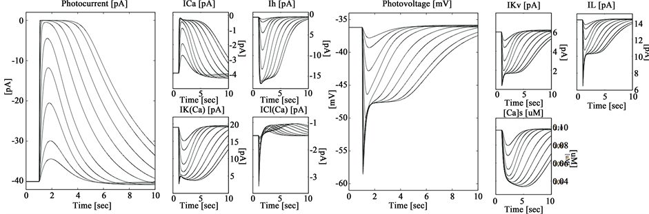
Figure 1. Typical calcium-activated chloride current (ICl(Ca)) and calcium-activated potassium current (IK(Ca)) from Usui’s model.

Figure 2. (A) Biphasic waveform applied on most transcorneal experiments; (B) Simulation of the voltage waveform used in our group in TES.
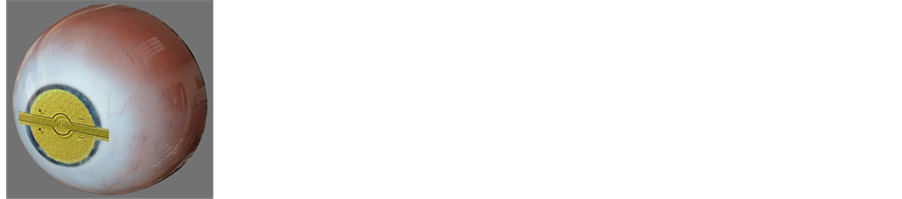
sections to properly fit the curvature of a curve surface like a contact lens case shown in Figure 3(A). A second approach array is shown in Figure 3(C). The porpoise of this second approach is focused to stimulate a smaller area of the cornea; however this approach can be used also to register aye surface potentials. So that the multi-electrode’s arrangement will fit the curved surface of the cornea as shown in Figure 3(C).
Polyimide is a soft transparent layer after spin coating and soft baking, than it fits curve surfaces. If required, these thin-film microelectrodes could be platinized or gold covered to increase the thickness and surface roughness; however Titanium electrodes have smooth surfaces and high impedance.
Process Development
The microelectrodes consist of alternating layers of polyimide-titanium-polyimide, which are patterned using reactive ion etching. The microelectrodes are fabricated over a thin silicon wafer that is used only as a sacrificial layer [25] -[27] . The titanium electrodes are fabricated over a thin silicon substrate and covered with a nitride layer. Manufacturing process using standard micro fabrication techniques LIMEMS-Poly MUPs. The Polyamide flexible substrate have demonstrated its biocompatibility, feasibility and efficiency [17] [18] .
The masks are used to write different patterns. This process used three different masks to manufacture the microelectrodes array described below and shown in Figure 4:


 (A) (B) (C)
Figure 3. (A) The multi-electrode’s arrangement is supported by a thin layer of polyimide that is hewn into triangular sections to properly fit the curvature of a contact lens; (B) Shows an interconnection schema between electrical signals and microelectrodes array; (C) Shows an alternative flexible polyimide microelectrodes array coupled to the surface cornea.
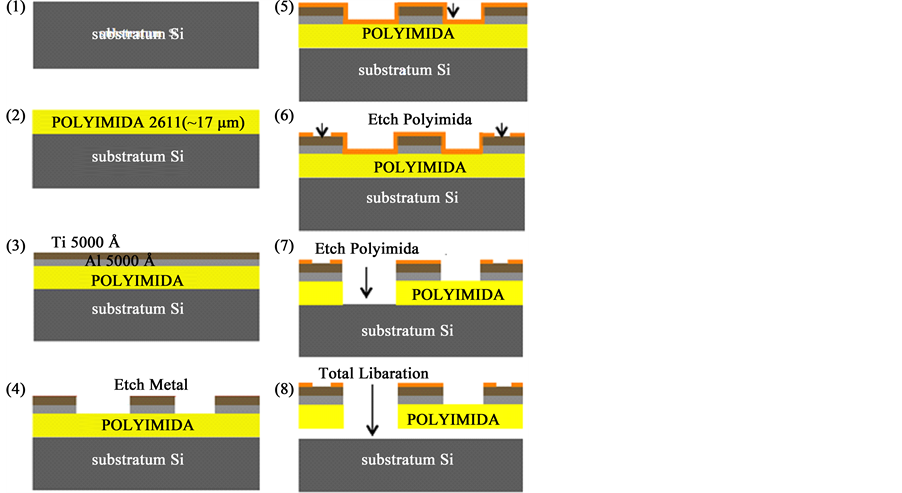
Figure 4. MEMS processing consists of alternating layers of polyimide-titanium-polyimide, which are patterned using reactive ion etching.
Mask # 1: Define the tracks, pads and microelectrodes in metal (titanium).
Mask # 2: Define the cavities, what serve as contacts for the slopes and the microelectrodes.
Mask # 3: Define a petal-shaped structure in structural material (polyimide)
Using standard micro fabrication techniques such as: lithography, evaporation tanks, reservoirs by PECVD, deposits spinner, dry etched by RIE, wet etching in selective etching solution and etching electrolysis in alkaline solutions. The following manufacturing process is developed (Figure 4).
Step 1: Deposit by evaporation of 1000 Å titanium and 5000 Å aluminum, sacrificial layer by etching electrolysis.
Step 2: Deposit polyimide for spin coating at 2000 RPM @ 17 μm, being the structural material and Polymerization polyamide by heat treatment, the ramp used is shown in Figure 5.
Step 3: Adhesion Polyimide to metal layers by RIE and Deposit evaporation titanium (5000 Å), this layer corresponds to the structural material, this deposition technique ensures better adhesion to the polymers.
Step 4: Lithography mask # 1, the technique is used for wet etching, engraving titanium for manufacturing microelectrodes and tread connection, corresponding to electrical part of the device.
Step 5: Deposit for spin coating polyimide, structural encapsulating layer and isolation the titanium structures.
Step 6: Etching by “dry etching technique” mask # 2, using silicon nitride as the masking material, carrying the masking photolithography to etch the contacts in polyimide by RIE.
Step 7: “dry etching technique” mask # 3, just as the process previous the mask # 3 is etch, what corresponds to structural part of the device.
Step 8: Engraving of aluminum by electrolysis, for total liberation of the micro fabricated device is immersed in an alkaline solution (2M-NaCl), aided by a positive voltage of 0.5 @ 500 mA for etching of aluminum.
Electrodes have lower level than lateral polyimide edges in order that metal get contact through conductive liquid solution.
Si is the supporting substrate, which is used only during fabrication processing. In order to release the Si from the polyimide conventional electrolysis is used; 2 Mol of NaCl, 0.5 volts @ 0.5 A [25] [28] . Flexibility of polyimide and its capacity to adopt curved shapes is shown in Figure 8. The developed technique can be applied to other curved shape.
4. Results
4.1. Manufacturing Results
Polyimide 2611 Kapton from Dupont was used as supporting microelectrodes substrate. Polyimide 2611 assures good mechanical manipulation since let 10.5 μm thickness [29] [30] .
Polymerization testing was done among various samples M1 to M5 using different thermal polymerization ramps. We got best results with M5 sample polymerized according to temperature variation shown in Figure 5.
Absorption polyimide test was done by FTIR. Results are shown in Figure 6. M5 sample got the highest absorption coefficient. Imida 4 and Imida 2 both have the highest absorption and the lowest solvent NMP undesired debris, letting good biocompatible and flexibility properties required.
4.2. Polyimide Roughness Measurements
Adhesion between metal and polymers is an important issue to consider. To ensure excellent adhesion, wear is done by RIE to increase the mechanical bond [31] . AFM measurements show that RIE procedure got a better roughness assuring the highest adherence between metal and polyimide as shown in Figure 7. Figure 7(A) shows a 2611 polyimide surface about ~8.5 μm thickness without wear while Figure 7(B) shows 2611 polyimide surface with wear. We show in Graph 1 a numerical comparison of roughness: without wear and with wear. An increase to peak to peak value, depth of valley and peak height of surface with wear, after RIE, is higher than without-wear assuring a better adhesion between metal and polyimide.
4.3. Microelectrodes over a Flexible Polyimide Substrate
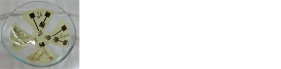
We show in Figure 8(A) the multi-electrode’s arrangement fabricated over a thin layer of polyimide that properly fits the curvature of a contact lens. Figure 8(B) shows an arrangement of sixteen electrodes over a polyimide substrate, which is a multipurpose set. In TES is coupled to the cornea through the sixteen electrodes at the
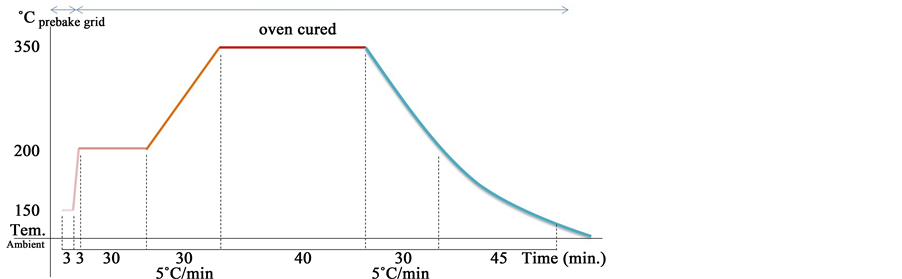
Figure 5. Ramp Thermal Polymerization of polyamide by heat treatment.
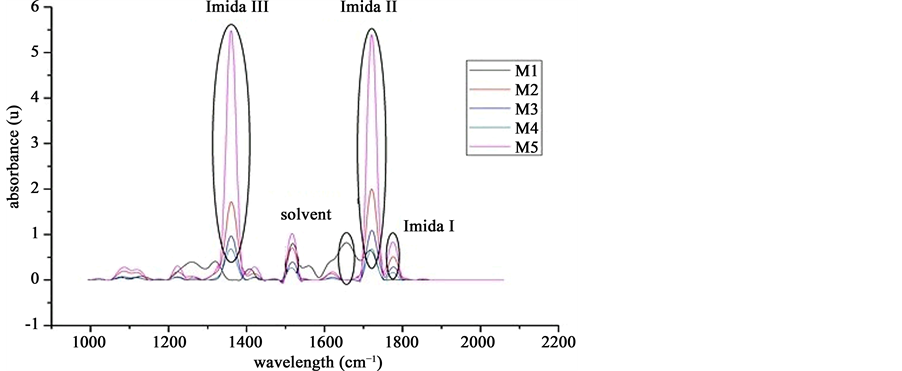
Figure 6. Wavelengths of interest in the range of 1200 - 1900 ʎ.

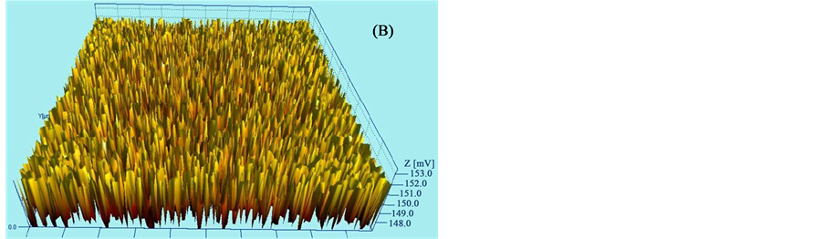
Figure 7. Roughness of the polyimide (A) before and (B) after wear by RIE to increase mechanical bond.

Graph 1.Polyimide roughness measurements.
 (A) (B)
Figure 8. (A) Microelectrodes over a curved surface; (B) Microelectrodes over a Flexible polyimide Substrate.
center of the polyimide artifact and connected the an electronic system by the lines at both lateral outputs. The polyimide artifact can be used in other applications like cell culture and register membrane potential.
4.4. Microelectrodes Electric Test
The microelectrodes under test were stimulated with low frequency (0 - 10 khz) sine waves, square, triangle and saw tooth. It can be concluded that the inner capacitances and inductances are negligible since, as can be seen in Figure 9, there is no distortion between (A) input (B) output signals through microelectrodes.
4.5. Non-Conventional Signal Generator
An electronic system generates non-conventional signal generator like Usui’s ionic currents among others. The hole system has a friendly software interface that let call any one of pre programmed Usui’s ionic currents.
A graphical user interface allows the generation of sixteen stimulation signals. The Hardware-software based waveform generator can produce sixteen different signals, each one characterized by its shape, amplitude, and frequency. Waveform shape is acquired from a set of discrete X(n) waveforms previously defined. Waveforms can be acquired also graphically by a virtual draw tool or even by a mathematical model. These signals are transmitted using a simple USB port connected to microcontroller that generates the sixteen stimulation channels.
The stimulation system is able to recreate complex waveform as the ones found in electrophysiology. This scheme can be used to obtain a class of multichannel stimulator that can be the core part of several biomedical applications.
The desired action potential is sketched by friendly software showed in Figure 10. Each wave forms can be acquired graphically by a virtual waveform draw tool, shown at top of Figure 10 like a graphic equalizer. A set of sixteen predefined waveforms can be selected from the button array in the lower of Figure 10. The friendly software allows to define and select any new action potential required. The selected waveform is estimated by a set of FIR filters. The FIR filter output is programed into a microcontroller’s memory, allowing converting the digital data into an analogue signal
Then the output of an electronic system can be connected to the microelectrodes array to stimulate the cornea, a tissue or even a cultivated cell by arrangement shown in Figure 8(B). Therefore waveforms and its parameters represent specific biological ionic currents or any other non-conventional waveform required shown in Figure 11. Electronic system details are not discussed in this paper.
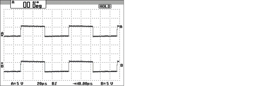
Figure 9. Electric Test. The microelectrodes were stimulated with low frequency (0 - 10 khz), there is no distortion between (A) input-(B) output signals.
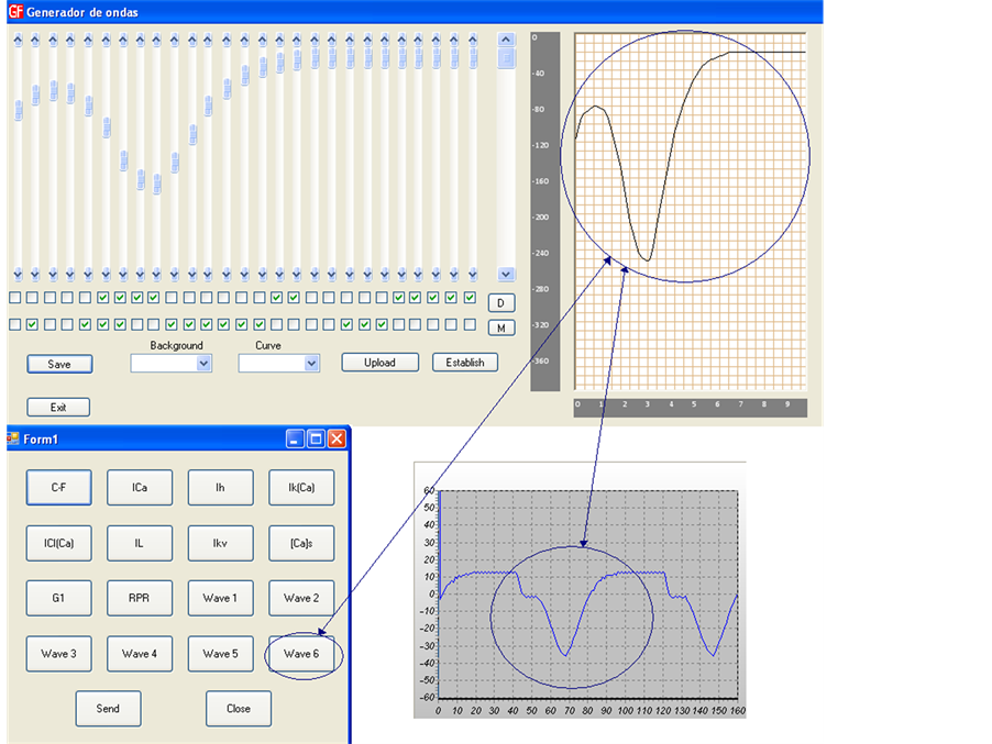
Figure 10. Waveforms can be acquired graphically by virtual waveform draw tool, a set of a x(n) vector or by a mathematical model.
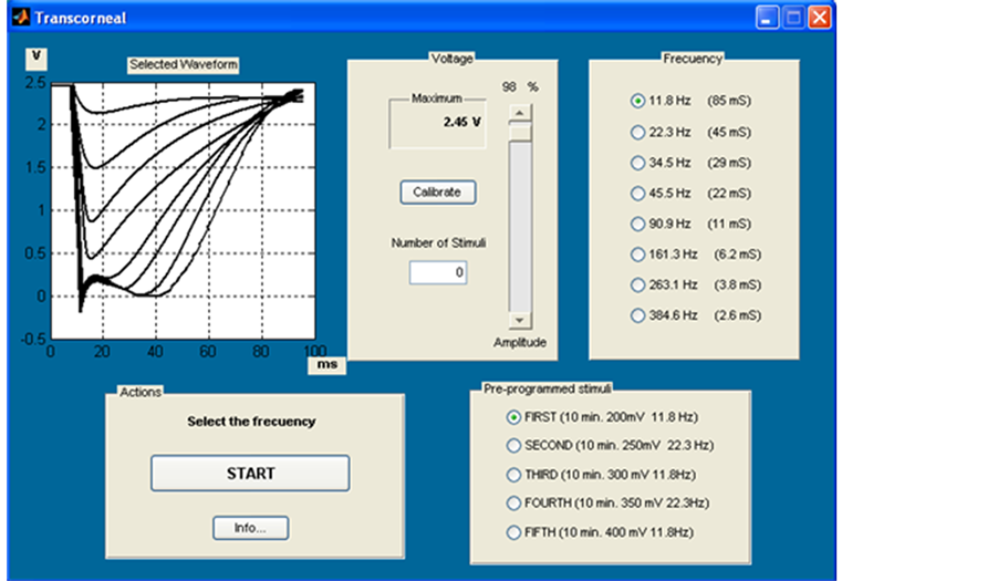
Figure 11. Waveforms and its parameters are selected from a set of specific biological ionic currents or any other non-conventional waveform.
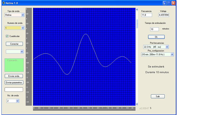
Figure 12. A Typical waveform we applied in TES. Amplitude values are selected from −70 mV/50nA to 180 mV/500µA and from −1.5 V to 2.8 V, and frequencies: from 11.8, 22.3, 34.5, 45.5, 90.9, 161.3, to 263.1 Hz.
As a first approach, we applied eyelid stimulation to two young healthy voluntary. The applied waveform is shown in Figure 12 using amplitude values from (−70 mV/50nA to −1.5 v) up to 180 mV/500µA to 2.8 v ), and frequencies 11.8, 22.3, 34.5, 45.5, 90.9, 161.3, 263.1 Hz., During the test, patients reported subjective perceptions, emphasizing the sensation phosphine and in no case neither pain nor uncomfortable sensations were described when eyelid stimulation was applied.
Patch clamp is widely used in cell electrophysiology allowing the study the performance of single or multiple ion channels in cells. Many patch clamp amplifiers do not use true voltage clamp circuitry, but instead are differential amplifiers that use the bath electrode to set the zero current (ground) level. We can use this proposal to understand the effect of time varying electrical stimulation over specific ionic channels. We can stimulate cells by specific time varying signals, instead of only by patch clamp DC step voltage techniques. Cell recording on the cell can be acquired by the same Flexible Polyimide Microelectrodes Array proposed in this papers and shown in Figure 8(B).
5. Conclusions
We proposed a new process for the manufacture of microelectrodes in a flexible substrate to be applied over the surface of the ocular glove. Its feasibility and efficiency have been demonstrated. The simple procedure to hewn polyimide into sections to properly fit the curvature of a contact lens case avoids other costly processes used in deposit of metals over curved surfaces. However, thermal molding after processing is still an appropriate issue.
Using these procedures, most self-assembly processes, with silicon circuits, compound semiconductor devices, and passive elements like micro coils, micro antennas, etc. can be integrated into thin flexible curved plastics and properly operated. We show that micron-scale metal interconnects can be incorporated into a thin flexible plastic substrate, and how the structure can be encapsulated in a biocompatible polymer. The developed techniques can be also applied to stimulate cell bodies in a great variety of applications.
The flexibility to generate any desired action potential opens fresh opportunities to brand new experiments in trancorneal stimulation. Non-conventional waveforms can reproduce any real biological waveform with 99.9% accuracy like Usui’s ionic currents. Complex waveform and its parameters can be easily controlled with conventional general-purpose electronic technology feasible at hand. These new methods to stimulate the retina open brand new opportunities to understand more precisely the neuro-protection effects of electrical stimulation at the inner retina. Most of the diseases derivative in vision lost are related to retinal degenerations (RDs) like retinitis pigmentosa (RP) and age-related macular degeneration (AMD). RDs are health problems growing up all over the world, and TES is an alternative to help people. Optimal TES parameters can be investigated, observing the effects of firing specific inner retinal neural structures
Acknowledgements
This paper was carried out by the support of the National Science Council and Technology of México, CONACyT, Hospital Dr. Luis Sánchez Bulnes. (APCM, México), Instittuto Politécnico Nacional, IPN) and the Instituto Nacional de Astrofísica, Optica y Electrónica (INAOE, Mexico) who helped in FAB facilities.
Cite this paper
Luis Niñode-Rivera,Fidel W.Pérez-Tovar,Jorge SantiagoAmaya,Félix GilCarrasco, (2015) Flexible Polyimide Microelectrodes Array for Transcorneal Electrical Stimulation. Journal of Biomedical Science and Engineering,08,544-554. doi: 10.4236/jbise.2015.88051
References
- 1. Gelkeler, F., et al. (2006) Phosphenes Electrically Evoked with DTL Electrodes: A Study in patients with Retinitis Pigmentosa, Glaucoma, and Homonymous Visual Field Loss and Normal Subjects. Investigative Ophthalmology & Visual Science, 47, 4966-4974.
http://dx.doi.org/10.1167/iovs.06-0459 - 2. Schatz, A., et al. (2011) Transcorneal Electrical Stimulation for Patients with Retinitis Pigmentosa: “A Prospective, Randomized, Sham-Controlled Exploratory Study”. Investigative Ophthalmology & Visual Science, 52.
- 3. Naycheva, L., et al. (2013) Transcorneal Electrical Stimulation in Patients with Retinal Artery Occlusion: A Prospective, Randomized, Sham-Controlled Pilot Study. OphthalmolTher, 2, 25-39.
http://dx.doi.org/10.1007/s40123-013-0012-5 - 4. Robles-Camarillo, D., et al. (2013) The Effect of Transcorneal Electrical Stimulation in Visual Acuity: Retinitis Pigmentosa. J. Biomedical Science and Engineering, 6, 1-7.
http://www.scirp.org/journal/PaperInformation.aspx?PaperID=37958 - 5. Naycheva, L., et al. (2013) Transcorneal Electrical Stimulation in Patients with Retinal Artery Occlusion: A Prospective, Randomized, Sham-Controlled Pilot Study. Ophthalmology and Therapy, 2, 25-39.
http://dx.doi.org/10.1007/s40123-013-0012-5 - 6. Morimoto, T., et al. (2010) Optimal Parameters of Trancorneal Electrical Stimulation (TES) to Be Neuroprotective of Axotomized RGCs in Adult Rats. Experimental Aye Research, 90, 285-291.
- 7. Xie, et al. (2011) Modeling and Percept of Transcorneal Electrical Stimulation in Humans. IEEE Transactions on Biomedical Engineering, 58, 1932-1939.
http://dx.doi.org/10.1109/TBME.2010.2087378 - 8. Miramoto, T., et al. (2005) Transcorneal Electrical Stimulation Rescues Axotomized Retinal Ganglion Cells by Activating Endogenous Retinal IGF-1 System. Investigative Ophthalmology & Visual Science, 46, 2147-2155.
- 9. Freeman, D.K., et al. (2010) Selective Activation of Neuronal Targets With Sinusoidal Electric Stimulation. Journal of Neurophysiology, 104, 2778-2791.
http://dx.doi.org/10.1152/jn.00551.2010 - 10. Sahin, M. and Tie, Y.M. (2007) Non-Rectangular Waveforms for Neural Stimulation with Practical Electrodes. Journal of Neural Engineering, 4, 227-233.
http://dx.doi.org/10.1088/1741-2560/4/3/008 - 11. Lee, S.W., Eddington, D.K. and Fried, S.I. (2013) Responses to Pulsatile Subretinal Electric Stimulation: Effects of Amplitude and Duration. Journal of Neurophysiology, 109, 1954-1968.
http://dx.doi.org/10.1152/jn.00293.2012 - 12. Kamiyama, Y., Wu, S.M. and Usui, S. (2009) Simulation Analysis of Bandpass Filtering Properties of a Rod Photoreceptor Network. Vision Research, 49, 970-978.
http://dx.doi.org/10.1016/j.visres.2009.03.003 - 13. Freeman, D.K., Rizzo, J.F. and Fried, S.I. (2011) Encoding Visual Information in Retinal Ganglion Cells with Prosthetic Stimulation. Journal of Neural Engineering, 8, Article ID: 035005.
http://dx.doi.org/10.1088/1741-2560/8/3/035005 - 14. Reich, L., Maidenbaum, S. and Amedi, A. (2012) The Brain as a Flexible Task Machine: Implications for Visual Rehabilitation Using Noninvasive vs. Invasive Approaches. Current Opinion in Neurology, 25, 86-95.
http://dx.doi.org/10.1097/wco.0b013e32834ed723 - 15. Gerding, H. (2007) A New Approach towards a Minimal Invasive Retina Implant. Journal of Neural Engineering, 4, S30-S37.
http://dx.doi.org/10.1088/1741-2560/4/1/s05 - 16. Park, R.I. (2014) The Bionic Eye. TheScientist.
http://www.the-scientist.com/?articles.view/articleNo/41052/title/The-Bionic-Eye/ - 17. Sekirnjak, C., Hulse, C., Jepson, L.H., Hottowy, P., Sher, A., Dabrowski, W., et al. (2009) Loss of Responses to Visual but Not Electrical Stimulation in Ganglion Cells of Rats with Severe Photoreceptor Degeneration. Journal of Neurophysiology, 102, 3260-3269.
http://dx.doi.org/10.1152/jn.00663.2009 - 18. Xie, J., Wang, G.-J., Yow, L., Cela, C.J., Humayun, M.S., Weiland, J.D., et al. (2011) Modeling and Percept of Transcorneal Electrical Stimulation in Humans. IEEE Transactions on Biomedical Engineering, 58, 1932-1939.
http://dx.doi.org/10.1109/TBME.2010.2087378 - 19. Cheung, K.C., Renaud, P., Tanila, H. and Djupsund, K. (2007) Flexible Polyimide Microelectrode Array for in Vivo Recordings and Current Source Density Analysis. Biosensors and Bioelectronics, 22, 1783-1790.
http://dx.doi.org/10.1016/j.bios.2006.08.035 - 20. Singh, P.S. (2011) Techniques for Characterization of Polyamide Thin Film Composite Membranes.
- 21. Chiang, T.H. (2008) Preparation, Microstructure, and Property Characterizations of Fluorinated Polyimide-Organosilicate Hybrids.
- 22. IynnDunson, D. (2000) Synthesis and Characterization of Thermosetting Polyimide Oligomers for Microelectronics Packaging.
- 23. Ho, H., Saeedi, E., Kim, S.S., Shen, T. and Parviz, B.A. (2008) Contact Lens with Integrated Inorganic Semiconductor Devices. Proceedings of 21st IEEE International Conference on Micro Electro Mechanical Systems (MEMS), Tucson, 13-17 January 2008, 403-406.
http://dx.doi.org/10.1109/memsys.2008.4443678 - 24. Seo, J.-M., Kim, S.J., Chung, H., Kim, E.T., Yu, H.G. and Yu, Y.S. (2004) Biocompatibility of Polyimide Microelectrode Array for Retinal Stimulation. Materials Science and Engineering: C, 24, 185-189.
http://dx.doi.org/10.1016/j.msec.2003.09.019 - 25. Zelmat, S. (2006) Etude des proprieties électriques d’un matériau polyimide à haute température: Application à la passivation des composants de puissance en carbure de silicium.
- 26. Doering, R. (2008) Handbook of Semiconductor Manufacturing Technology. 2nd Edition.
- 27. Chena, Y.-Y. (2009) Design and Fabrication of a Polyimide-Based Microelectrode Array: Application in Neural Recording and Repeatable Electrolytic Lesion in Rat Brain.
- 28. Metz, S. (2005) Partial Release and Detachment of Microfabricated Metal and Polymer Structures by Anodic Metal Dissolution.
- 29. HD MicroSystems Technical Service Representative. PI-2600 Series—Low Stress Applications. 2009.
- 30. Kaptein, J.G. (2008) Inductively Powered Implant for Monitoring and Application of Telemetric Metronomic Photodynamic Therapy.
- 31. Olver, K.A. (2009) A New Procedure for the Application and Curing of Polyimide Film on Gold Coated Silicon Wafers.