Technology and Investment
Vol.3 No.4(2012), Article ID:24851,4 pages DOI:10.4236/ti.2012.34036
Embedded Processor’s Application to the Beam Quality Analyzer
Electronic Information Engineering Department, Changchun University of Science and Technology, Changchun, China
Email: wcxhao@sina.com
Received June 1, 2012; revised July 1, 2012; accepted July 8, 2012
Keywords: Embedded; Beam Quality; PC104 Standard; Real Time Operating System
ABSTRACT
Introduces the bus standard of an embedded processor named PC104, discusses the embedded laser beam quality analyzer software and hardware design based on the standards, and gives the test results of the instrument. It was shown that if the embedded technique was used for beam quality measurement, functional integration of the beam quality analyzing equipment can be achieved. That is the all in one system including the function of data acquisition and processing, beam quality factor calculation, results shown and the network communication, which has advantages such as small volume, powerful function, high reliability, good extension and so on. A better solution for application the beam quality analyzer into the industry field was provided in the paper.
1. Introduction
One of important goals has been pursued by the modern testing equipment designer is functional integration and small size. With the continuous development of laser technology, lasers have been widely used in the industrial production and scientific research fields [1]. Beam quality testing equipment can provide valuable information about all the spatial characteristics of laser beam, beam propagation characteristics, laser’s effective use and other aspects. These can also provide the basis for adjustments and modifications for design efficiently to ensure highquality laser output [2]. The traditional PC-based or the industrial computer for beam quality testing equipment can not be used in the space-constrained industrial field due to its bulky and more redundancy. However, if the beam quality is unknown in the industrial field, the laser will be hardly or even not put into use, and therefore it is an urgent requirement to use the embedded processor into developing high-performance testing equipment in the field of laser parameter testing.
With the development of embedded computer technology, the embedded processor was paid universal attention by the control engineering as its advantages such as small size, low power consumption, high reliability and so on. This paper describes briefly the PC104 standard based on which developed a portable, compact embedded laser beam quality testing equipment adopting the beam quality factor method recommended by the International Organization for standardization, integration the laser optics, modern integrated circuit technology and embedded technology.
2. Brief Introduction of PC104 Standard
In the year of 1987, the related factory introduced a PC104 embedded computer modules due to the shortcoming such as huge in size, high power consumption, low reliability lie in the PC in the filed of industrial control. PC104 module is a kind of structural module with the characteristics such as low-cost, high reliability, which can be configured into a product quickly. The bus module of which is fully compatible with PC bus system on the aspects of architecture, hardware and software, it is suitable for embedded applications as it adopts a compact stack structure. PC104 bus is a simplified version of IEEE-P996 actually, which is a bus specification specially designed for embedded system applications. It provides a standard system platform for embedded applications, and has an open PC bus architecture. Developers can develop different functional boards to adapt different functional requirements and on-site equipment requirements of different period, which can be combined into different control devices. Using the PC104 bus module system, the development cycle of a product was shorten greatly, the product also is low-cost and low risk which reflects the latest technology fitful for the production of high-density, small size and portable testing equipment. The development platform for PC104 bus system and for the existing general-purpose computer systems are identical, so all existing development software can be used, general-purpose computer can also be used to develop the application program for the control systems.
According to IEEE standard, the main difference between PC104 bus device and PC bus devices are:
• Small module size, which is only 90 mm.
• No chassis, panel or bus board, which is embedded in the other module or system as normal component.
• PC104 modules stacks using longitudinal and lateral plug connection mode, the usual edge plug contact is changed into a reliable pin stack access, strong antivibration and shock, high reliability which referred to 64-pin P1 and 40 pin P2.
• Single +5 V power supply, lower power consumption (typical value of 1 - 2 W/module) and a smaller bus drive current (that is about 6mA).
PC104 system usually consists of several different functional modules, such as CPU module, LCD module, floppy drive module, CRT module, hard drive module, and so on. These modules connect through the bus connector P1, P2 and are fixed by using the standard mounting holes, which forms a compact stack-fit structure. PC104’s hardware architecture and software development are compatible with IBM PC, most developers are familiar with them, so relative to the special structure of PLC, 80C196, PC104’s development, maintenance and expansion are very convenient.
3. Embeded System Design
The hardware overall block diagram of the embedded beam quality analyzer was shown in Figure1. Seen from Figure 1, this instrument consists of the continuous attenuation system [3], focusing imaging system CCD, frame grabber, motors, control card, embedded PC104 modules and LCD module. This is responsible for the continuous laser beam attenuation, controlling the CCD camera to execute laser beam multi-point sampling, performing image processing algorithms, displaying the system measurement result at real time.
The electrical system included CPU, CCD camera, data acquisition card and stepper motor controller. Among which, CCD camera is responsible for detecting the laser spot, data acquisition card is responsible for collecting image data and transmitted them to the PC104 for display processing. That is, the image acquisition card collects the laser spot intensity data, expressed by the gray scale,
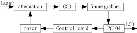
Figure 1. Overall block diagram of the embedded beam quality analyzer.
CPU makes a decision whether the image data are effective, if it is false, CPU controls the stepper motor rotation via the serial port, the rotation sport can be translated into a one-dimensional moving motion by the screw, moving result is to change the sampling position, by using another motor, we can implement a continuous attenuation to change the intensity received by CCD so that the laser energy is fitful for adapting camera to capture image and PC104 can obtain the key data, finally complete its measurement task.
The testing instrument used PC104 module as a “macro component”, designed a substrate, above which set PC104 bus. PC104 modules was plugged into the substrate just like an ordinary application function plate, and then plug other specific functional plate in the substrate on the board, mainly including control card templates, capture card templates, liquid crystal display template, finally a complete application system was constructed in the paper. This design is characterized by using a specific I/O to insert an embedded computer (that is PC104 macro component) instead previous inserting the I/O expansion board into the computer, which reflected the design of embedded systems.
4. Choice of Discrete Module
4.1. Choice of PC104 Module
The beam quality measurement instruments need complete laser spot image data acquisition, implementation of filtering algorithms, data operations and display, network communications and other functions, taking into account the integration and the design of portable equipment, the processing equipment core was no longer a PC but an embedded processors called PC104 module, whose specific model is PCM-3386. PCM-3386 is an embedded control module with cost-effective and extremely compactable size. There is a high-performance 16-bit embedded processor on-board, which is an internal 32-bit RISC architecture and is compatible with 80C186 processor with high performance, frequency up to 1 GHz, built-in 100 M Ethernet, and which supports 512 MB SDRAM. Its instruction is compatible with other X86 microprocessor. On-board features include 10/100 M Fast Ethernet interface, supports standard IDE interface, parallel port, serial port, PS/2 keyboard port, CFC electronic disk interface, LCD interfaces and so on.
4.2. Choice of CCD Camera
Array CCD camera module is the core component of the laser spot collection; its performance determines the overall system measurement accuracy. The following aspects should be considered when we choose array CCD camera as image sensor.
1) High resolution It is well known that the camera’s resolution is higher, the outline of objects or images detected by CCD is more slightly, and the measurement accuracy is higher, which requires that there are enough pixels in the array CCD camera.
2) Low noise The noise from CCD camera affects the subtle contours of images collected to some extent, the main consideration in the camera system is thermal noise, dark current noise which requires to choose a low-noise, small dark current CCD camera, while in the software part, the background noise should be considered and eliminated.
3) Wide dynamic range The dynamic range of CCD camera depends on the maximum signal level and noise level of the linear response. Resolution requires an increase in the number of CCD pixels, resulting in the maximum charge may be stored to reduce, so that the dynamic range is smaller, so the choice of CCD camera must be integrated into the above indicators. The system is normalized, 1 and 1/e2 are responding, so the camera’s dynamic range should be greater than 10 dB.
4) Response spectrum The spectral range of the system requirements is between 400 nm to 1100 nm, selection of CCD camera should consider whether there is response and the degree of response should be high enough, so we chose silicon CCD in the system.
Considering above factors comprehensively, the system selected near infrared camera (that is NIR) called UM-301. At the point of 945 nm wavelength, the product is more sensitive than the ordinary camera about four times. Fuzzy points on the screen are reduced to a minimum, and its dynamic range is higher than the ordinary camera. In addition, UM301 camera has asynchronous capture function; this function can let the camera collect high-resolution images at a high speed shutter without any ambiguity point. The module has a standard EIA/ CCIR output, which determines that the following image acquisition card should be analog frame grabbers.
4.3. Choice of Data Acquisition Module
As the core structure of image processing in the embedded beam quality testing instruments is PC104 standard, so the image acquisition card in the selection criteria must be PC104 interface card [4], otherwise the system’s compact modular design can’t be realized. After considering t various factors, we chose DH-VT121 image acquisition card produced by Daheng Company finally. The card is based on PC104-PLUS bus standard, it can do dual simultaneous acquisition with high-quality image quality and stability. Which are mainly used in the small video image processing and the controlling devices based on the embedded operating system.
4.4. Choice of Stepper Motor and Design of a Stepper Motor Control System
Stepper motor is a kind of electromagnetic actuator which can translate the input pulses into rotation or linear incremental motion. Input one pulse on each step, a stepper motor steps a shaft angle increment. All the motor back to the corner is proportional to the total number of pulses being entered; the corresponding speed depends on the input pulse frequency. After analysis, the system used two-phase stepper motor as the enforcement components; the specific model is 17H150H-04A. After that we designed a stepper motor driving and controling system. In order to form a standard PC104 architecture, we designed the electrical board with a standard PC104 bus plug [5], selected the high-power darling-ton tube to drive stepper motor, chose the new AVR microcontroller as stepper motor controller, and chose opto-coupler for electrical isolation of weak and strong.
People usually choose different amplifier and different parameter element to construct a step motor driving circuit [6], but this paper used two-phase step motor as execution mechanism, which needs amplify four signals separately, it is hard to keep completely identical for single transistor amplifying circuit which leads to run unstably especially the motor runs with a large power. So we chose L298N which is an integrated circuit with constant voltage and constant current bridge-type 2A driving ability, there are four channels logic driving circuit in the chip, so we can use it to drive two direct-current motor or one two-phase step motor. Experiment showed that this driving circuit has characteristics such as stability, simple interface and so on.
4.5. Software Design
The instrument’s software flowing chart was shown in Figure 2. Firstly, complete the system’s initialization, including setting the starting position of stepper motor, stop position, step distance, the number of camera images collected, the measured wavelength of the laser, the camera pixel size information and so on. Secondly, waiting for the start button was pressed, a measurement process began. under the control of PC104, the stepper motor moved forward in accordance with the given step distance, which determined a location that is also called sampling point, PC104 collected the laser beam intensity according to the gray value to determine whether the CCD is saturated, If the judge is in the affirmative, then increased the attenuation factor until the camera is unsaturated, if the judge is negative, then capture the image and save the processing results. Thirdly, the embedded processor-PC104 determine whether the number of images collected less than the default value, if the judge is yes, then controlled the stepper motor to move forward step further, if the judge is no, the sampling process is over. Finally, PC104 module processed data obtained before, including using spot diameter and the acquisition value of the location information to fit the curve, obtained the beam diameter, beam divergence angle the diffraction limit factor parameter, and displayed the data processing results in the touch screen, which included the two-dimensional distribution of the laser spot image, three-dimensional distribution, the performance parameters of the laser beam, and the laser beam fitting curve.
The whole system designed in the paper was shown in Figure 3. Running showed that this system has characteristics such as small size, integration, stable running,

Figure 2. Software flowing chart of the system.
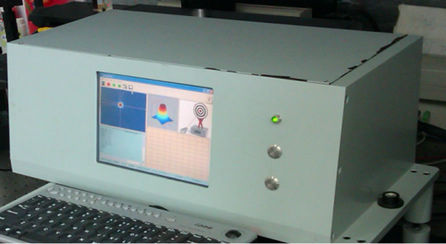
Figure 3. Embedded laser beam quality analyzer.
high measurement precision and so on, which satisfied the demand of ±6% testing precision.
5. Conclusion
The embedded beam quality analyzing system has been developed successfully, compared with some existing similar function instruments; it has advantages such as a flexible system configuration, easy monitoring and controlling to facilitate expansion, easy debug setting, and effectively automatic measurement for beam quality advantages and so on. The software interface of this in strument is clear, simple and beautiful. As using a touch screen to control the measurement process and display the result, say a site operator, the man-machine interface is friendly, and easy to be operated. However, the overall function of the instrument need to be further developed and improved.
REFERENCES
- B. Dai, “Laser Technology and Industrial Applications,” Equipment Manufacturing Technology, Vol. 3, No. 2, 2009, pp. 127-128.
- J.-Z. Zhen, S. H. Guan and Q. X. Yu, “Evaluation Methods for Laser Beam Quality,” Journal of Dalian Nationalities University, Vol. 10, No. 1, 2008, pp. 53-57.
- H. X. Tian, J. F. Yang and X. L. Ma, “Design for Visible Video Zoom Optical System,” Acta Photonica Sinica, Vol. 37, No. 9, 2008, pp. 1797-1799.
- Y. Chen, X. P. Liu and H. Q. Ying, “High Quality and Portable Data Acquisition System Based on PC104 Bus,” Measurement & Control Technology, Vol. 28, No. 1, 2009, pp. 24-27.
- L. Xiao, J. H. Bai, G. S. Ji, Y. Q. Hu and X. D. Zhan, “Design of Motion Controller Based on PC104,” Mechanical & Electrical Engineering Magazine, Vol. 26, No. 6, 2009, pp. 68-70.
- P. X. Rong and Z. J. He, “Design of Numerical Control System for Stepper Motor,” Electric Machines and Control, Vol. 13, No. 2, 2009, pp. 272-275.