Natural Science
Vol.4 No.8A(2012), Article ID:21659,7 pages DOI:10.4236/ns.2012.428086
Explosions and seismic phenomena based on exciting acoustic-electromagnetic waves
![]()
1CIICAp, Autonomous University of State Morelos (UAEM), Cuernavaca, Mexico; *Corresponding Author: svetlana@uaem.mx
2Center of Geosciences, National Autonomous University of Mexico (UNAM), Juriquilla, Mexico
3Faculty of Earth Sciences, Autonomous University of Nuevo Leon (UANL), Linares, Mexico
4Physical Faculty, Taras Shevchenko National University, Kyiv, Ukraine
Received 14 June 2012; revised 20 July 2012; accepted 29 July 2012
Keywords: Underground Explosion; Nonlinear Passing of Acoustic Waves; Piezoelectric and Magnetic Plates; Difference between Natural Seismic; Volcanic and Industrial Events
ABSTRACT
During earthquakes and strong underground explosions it is possible to observe two different effects. The first one is connected with the destruction of media, and this causes acoustic and later hybrid acoustic-electromagnetic waves in an epicenter in the atmosphere and in the ionosphere. Another one is connected with cracks in crystals of rocks, which seems more interesting, because it is possible to recognize the natural earthquakes and industrial explosions. In the first effects due to nonlinear elastic modules the acoustic waves move through the lithosphere and transform their spectra from VLF (very low frequencies ~ 1 - 10 kHz) at a depth of about 30 km into the lower part of ELF (extremely low frequencies ~ 3 Hz - 1 kHz) on the Earth’s surface, then they pass the atmosphere and penetrate into the ionosphere. During the nonlinear acoustic passage through the atmosphere and the ionosphere, the spectrum transforms from ELF into ULF (ultra low frequencies < 1 Hz) range. In this review article the classification of spectrum and analysis of two cases of the destruction of rocks in the lithosphere are presented. The rocks possess piezoelectric and piezomagnetic properties. In this case, the electromagnetic emission is excited by the fracturing in plates of crystals. The difference of emission from piezoelectric and magnetic plates in cases of industrial explosions and natural seismic events including volcanic phenomena gives a possibility to analyze the method of its identification. The consideration is based on the model of the plate of a finite size with a uniformly moving crack.
1. INTRODUCTION
It is very important to investigate the mechanisms of the energy flows from the lithosphere into the atmosphere and the ionosphere caused by natural hazards (seismic and volcano activity, tsunami etc.). All mechanisms have different precursors [1,2] due three basic channels of the lithosphere-ionosphere connection, namely, electromagnetic, geochemical, and acoustic ones [3].
The acoustic channel of the lithosphere-ionosphere coupling seems quite effective. It is due to atmospheric acoustic waves excited by fluctuations of a terrestrial surface [4]. This channel is illustrated in different phenomena [5] like excitation of plasma waves and periodic structure in the ionosphere, the increase of transparency for radiowaves, linear and nonlinear generation of magnetic perturbations, and oscillations of Eand F-layers in the ionosphere caused by acoustic and acoustic-gravity waves, nonlinear transformation of spectra of waves in the atmosphere, the ionosphere, and the lithosphere [5- 10]. The last case is analyzed below in two cases: strong seismic explosions in simple media and in case of cracks in a crystalline plate [11].
2. MODEL AND EQUATIONS
The geometry of the excitation of waves by underground fracturing for two cases is in Figure 1. One case is connected with the destruction of media, and this causes acoustic and later hybrid acoustic-electromagnetic waves in epicenters in the atmosphere and in the ionosphere. Another case is connected with cracks in crystals of rocks. Both cases are illustrated in the same Figure 1.
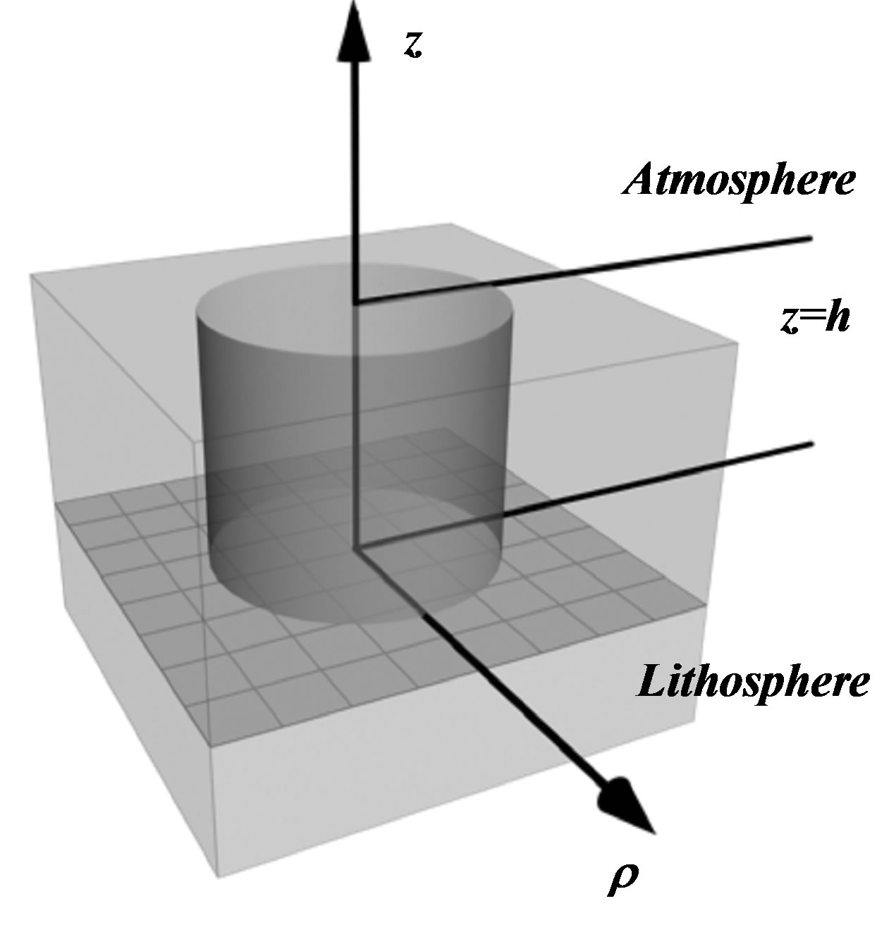
Figure 1. Geometry of the nonlinear passage of acoustic waves caused by underground fracturing through the lithosphere into the ionosphere.
The destruction and the excitation of waves including the case of cracks occur in an underground place in the depth h. After that the waves move to the Earth’s surface and into the atmosphere and the ionosphere.
It is a cylindrical surface around the place which is the source of waves. After that, the seismic burst-like envelope of a finite transverse scale begins their passing through the Earth to the lithosphere, the atmosphere, and the ionosphere. Their passing through the Earth is nonlinear for two cases mentioned in the introduction.
In the case of cracks in rocks it is necessary to analyze the piezo and magnetic crystals [12], and the whole process has been considered of a finite size with a uniformly moving crack. Its linear front is parallel to the optical axis of the crystal. The tip of the crack instantly begins the uniform motion at a time moment t = 0 and causes the electromagnetic emission at a moment t = T > 0.
3. NONLINEAR PASSING OF ACOUSTIC WAVES
The first case is the seismic destruction in the lithosphere at the depth h (see Figure 1), it is described by the elasticity theory in the geometry of cylindrical surface around the place in which there is the source of underground seismic explosion (or deformation of a plate). The elasticity theory for the case of the Earth’s crust as an isotropic uniform medium has the following the Newton’s equation for the mechanic displacement :
:
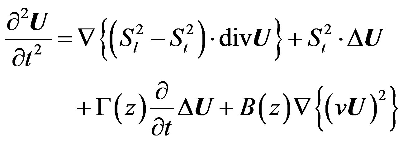 (1)
(1)
The coefficients G(z) and B(z) describe the viscosity and nonlinearity of the elastic isotropic uniform medium in cylindrical system of coordinates for the acoustic waves with longitudinal and transverse velocities  respectively.
The acoustic propagation in the atmosphere and the ionosphere is described by the following set of hydrodynamic equations:
 (2)
(2)
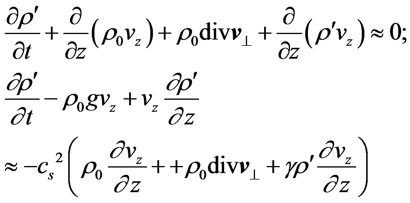
Here  are the components of the velocity of air
 ; r, p are its total density and pressure; g is free fall acceleration; r = r0 + r′, p = p0 + p′; where r0, p0 are the stationary values of atmospheric density and pressure
 ; and r′, p′ are alternating parts. The parameter H » 8 km is the average height of the atmosphere.
Additionally, this model uses the adiabatic equation for pressure with the adiabatic constant , and
, and
 is the kinematical viscosity of air. It is assumed that nonlinearity is moderate and only quadratic nonlinear terms are preserved in Eq.2. Note that all mechanisms of nonlinearity are essential. Also it is supposed that the acoustic wave moves preferentially vertically upwards, and inequalities |vx,y| << vz are valid. In a linear approximation, when viscosity is neglecting, from Eq.2 one can see that for the acoustic wave
 , and the energy flux is
 .
.
We take into account the following dispersion law for vertically propagating atmospheric acoustic waves (AW):
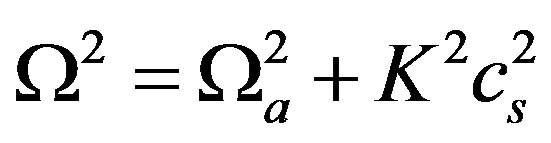 (3)
(3)
Here  is the cut-off frequency, and cs =
 is the speed of sound. Because of the fact that the attenuation of waves caused by the viscosity strongly grows with an increase of the frequency (as ~
 ), it is possible to expect that the effect of increasing atmospheric acoustic waves is essential only at frequencies W £ 10 s–1. The observations confirmed this conclusion [1]. Within the lithosphere the vertical z-component of the acoustic wave is only demonstrated, the transverse profile is really smooth, and in modeling it is possible to neglect by the transverse acoustic components.
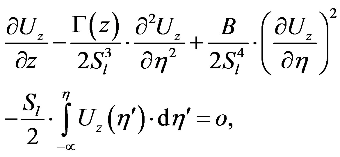
For the z-component the following equation is valid
 (4)
(4)
This is the equation of the Khokhlov-Zabolotskaya [11]. For the case of the atmosphere and the ionosphere it is necessary to introduce a new dependent variable V = vz , and the independent ones z,
  , x [11]:
 (5)
(5)
The evolution of low frequency part in the lithosphere described by Eqs.4 and 5 is shown in Figure 2. The initial burst is described in the following manner:

The normalizing for amplitudes of AW is A0 = 0.01 cm–1, ratio of nonlinear and linear elastic modules is , a dissipation coefficient for the frequency
  is taken 0.25 km–1.
The carrier frequency for ELF wave is chosen as f1 =  Hz.
Hz.
The input ELF wave is burst-like, i.e., it is a wave packet with an ELF carrier frequency  ~ 10 - 500 s–1; its envelope (modulation) frequency W ~ 0.1 - 5 s–1 is in the ULF frequency range:

The value of ρ0 determines a transverse scale of the initial pulse. The Eq.5 is solved numerically by using spectral methods.
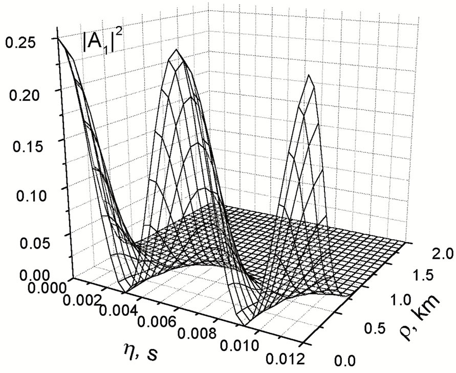
After an excitation at the Earth’s surface, the ELF wave is subject to nonlinearity that leads to a generation of higher harmonics and down-conversion, namely, the increasing of the ULF component. More than 100 harmonics are excited. The growth of higher harmonics leads to the formation of a saw-tooth-like structure. Such a structure dissipates due to viscosity. The ULF part of spectrum is not subject to dissipation, on the contrary, it increases due to this nonlinear interaction. When the transverse scale is ρ0 ~ 0.3 - 10 km, the diffraction is not important for the ELF wave but it can decrease the peak
 (a)
(a)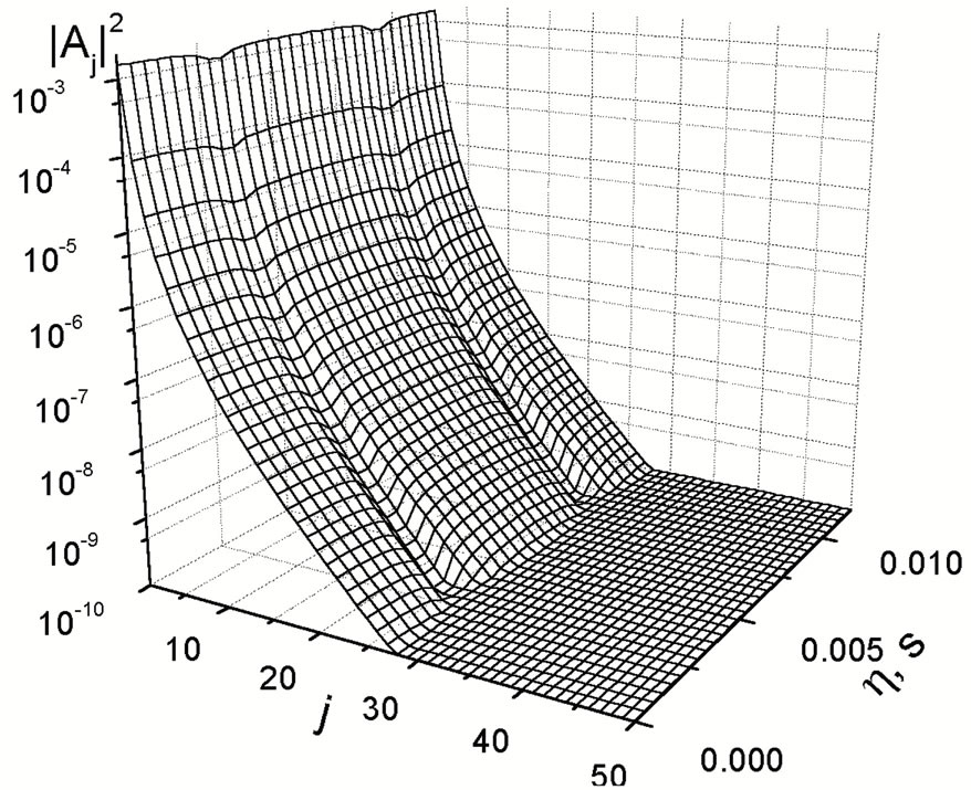 (b)
(b)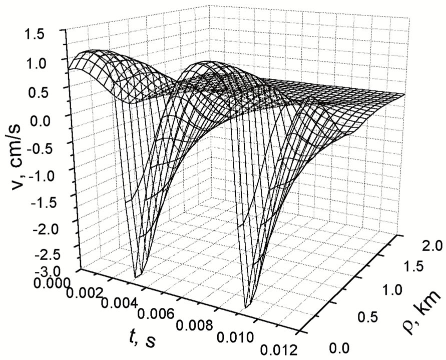 (c)
(c)
Figure 2. The nonlinear frequency conversion of AW (VLF AW – ELF AW) under passing through the lithosphere. (a) is
initial distribution  of the first harmonic; (b) is a distribution of
  for harmonics (j = 1,2,···), when the greatest ratio
  is observed; (c) is output distribution of the velocity of the ELF AW v(t,r) on the Earth’s surface. Here w0 = 5 × 10⁴ s–1, wELF =1000 s–1; r0 = 0.5 km.
amplitude of the ULF part. The results of the numerical simulations are given in Figure 3.
The efficiency of the nonlinear acoustic transformation is quite high. Within the framework of the specified model, the ULF acoustic-gravity waves (AGW) at frequencies 0.05 - 0.5 s–1 may reach the heights z = 200 - 300 km, where the maximum values of the density of free carriers of the ionosphere plasma occur.
In this analysis it is possible to take the classification of the spectrum. The underground fracturing causes VLF (very low frequencies ~ 1 - 10 kHz) at the depth of about 30 km, this initial spectrum changes during the passage into ELF (extremely low frequencies ~3 Hz - 1 kHz) on
 (a)
(a) (b)
(b)
Figure 3. Nonlinear frequency conversion of AW. The excitation of ELF AW with the amplitude of V0 = 30 cm/s. Here (a) is the distribution of velocity of the ULF AGW v(t,r) at the altitude z = 200 km; (b) is the distribution of velocity of the ULF AGW v(t,r) at an altitude z = 300 km. Here w0 = 30 s–1, W = 0.075 s–1; r0 = 25 km.
the Earth’s surface, then AW pass the atmosphere and penetrate into the ionosphere. During the nonlinear acoustic passage through the atmosphere and the ionosphere, the spectrum transforms from ELF into ULF (ultra low frequencies < 1 Hz) range.
4. CRACKING OF PIEZOELECTRIC AND MAGNETIC PLATES
The second case of explosion in rocks is connected with exciting of cracks. It is supposed that a piezo and magnetic crystal surrounds by a plate possessing similar mechanical and dielectric properties. It is demonstrated that time-dependent mechanical stresses, which exist in the vicinity of the apex of the crack, are sources of EM waves, see below.
Additionally the comparison of the EM emission (EME) due to piezoeffect and piezomagnetism results in the different conclusions. The EME is investigated for the piezoelectric crystals of the point symmetry group 32 and for the piezomagnetic crystals of Fd3m space group symmetry in the first approximation for piezocoefficients and in the zero approximation for deviations of elastic tensor of the crystal from one for an isotropic medium with similar mechanical properties. It is obtained that the magnetic field of the emission has lots of maxima as a function of its frequency; these maxima are determined by the crystal size and the velocity of the crack and are located in LF and ELF ranges of the spectrum. It is found also that a source of the emission is equivalent to a timedependent magnetic dipole for both piezoelectric and piezomagnetic crystals, and the values of the magnetization vector and corresponding magnetization current have been estimated. Then the equations of the motion of the medium and equations of the EM field, written in the crystallographic frame of the piezocrystal are:
 (6)
(6)
where r is the crystal density, Ui and sij are components of the displacement vector and mechanical stresses tensor, respectively, ¶j denotes a partial derivative with respect to xj;  are vectors of electric and magnetic field and corresponding inductions, respectively; c is the velocity of light. The constitutive equations for the piezoelectric crystal have the form:
 (7)
(7)
and for the piezomagnetic crystal:
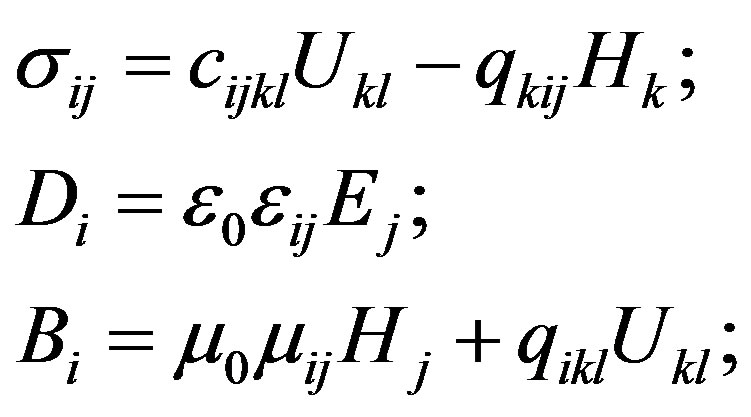 (8)
(8)
The quantities Uij, eij, and µij in Eqs.6-8 are dimensionless,  are components of the strain tensor, e0 and µ0 are electric and magnetic constants, respectively, cijkl, eikl, qijk, µij, eij are components of tensors of elastic, piezoelectric, piezomagnetic, magnetic, and dielectric constants, respectively.
Eqs.6-8 have been solved by using the Fourier transform on spatial coordinates within the infinite limits and the Laplace transform with respect to time t [12,13]. It is found that the non-stationary mechanical stresses in the vicinity of the moving tip of the crack have caused nonstationary polarization currents, which possess potential and vortical components inside a piezoelectric crystal and only vortical components inside a piezomagnetic one. The potential currents generate electric polarization current IP, but the vortical ones just are magnetization currents IM, or magnetic dipoles. In both cases namely the non-stationary magnetic dipole generates the electromagnetic radiation in the far zone and this dipole is created by the moving tip of the plate due to specific crystal symmetry related with the crystal piezoproperties (see Figure 4).
For estimations the material coefficients for piezoelectric quartz (in matrix representation from [14]) are used: ,
,  C/m2,
C/m2,  C/m2. Now, it is necessary to use the estimations obtained in [11] for the magnetic moment and vortex current created by a single moving displacement crack through a crystal of quartz:
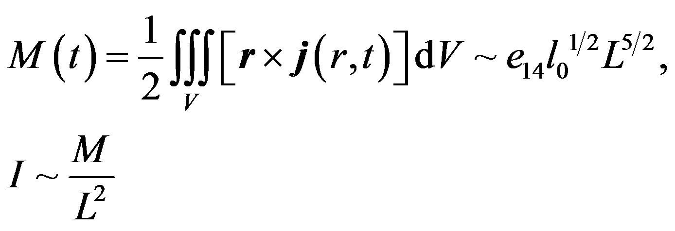 (9)
(9)
where L is the crystal size, and l0 is the initial size of the crack, which is usually close to several interatomic distance. When we set L » 1 m, l0 » 1 nm, the velocity of the motion of the crack is Vcr » 1.5 km/s, then we find M » 0.01··· 0.02 A∙m2 and corresponding polarization current I » 0.02 A.
It is possible to make the same for the magnetic moment and corresponding polarization current into the cracked piezomagnetic crystal CoFe2O4 by using the material coefficients from [13] q31 » 580, q33 » 700, and q15 » 550 N/A∙m and approximations:
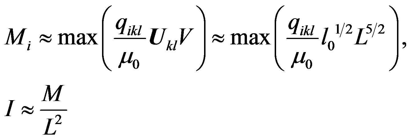 (10)
(10)
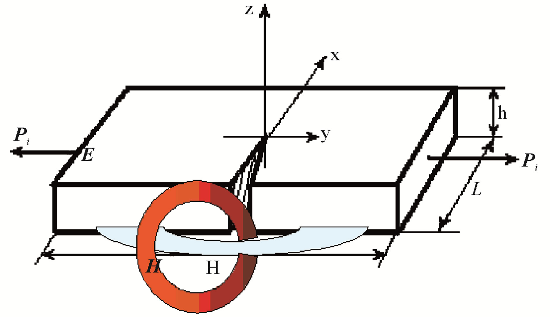
Figure 4. Moving crack and EM fields around it.
This gives M » 0.15 A∙m2 and I » 0.15 A. Therefore, the moving crack generates the vortex current inside piezoelectric materials, which is comparable with one inside the piezomagnetic ones. The pointed above magnetic moments, created by only one piezocrystal of the given size, at the distance r = 100 m generate the magnetic field with induction Be » 1 ´ 10–6 nT for the piezoelectric case and Bm » 1 ´ 10–5 nT for the piezomagnetic one.
These fields are very small to detect a single crack only. But we suppose that inside the cracked rock massive with a characteristic size of about 100 × 100 × 100 m3 there are 104 cracks. Hence, the magnetic field at the distance r = 100 m can potentially be enhanced up to 1 nT, when a great crack crosses such a rock massive and all piezocrystals generate correlated magnetic fields. In VLF range f ~ 1 kHz, the magnetic fields of pointed above magnitudes ~ 0.001··· 0.1 nT can be detectable. It is investigated the solutions of magnetic dipoles and magnetic field using an approximation for mechanical stresses both around of the crack, and for the wave of unloading.
In both cases it is necessary to find the effect that the frequency dependence of the magnetic field has two parts, created by unloading wave and by the tip of a crack, respectively.
The frequency dependencies of the magnetic field generated by the tip of the crack and wave of unloading are given in Figures 5 and 6. The dimensionless frequency is .
.
One can see that the field created by the tip of the crack has several maxima at the dimensionless frequencies  3,
3,  9,
9,  16 whereas the one created due to unloading wave has a single one at
  » 1.5. The value of such a single maximum is dominating and exceeds the value of the first maximum due to the motion of the tip about 4 times. For the values L = 1 cm and Vcr = 4 km/s (a small crack) the corresponding frequencies are
  190 kHz,
 » 95 kHz. The fields at this frequency range dissipate strongly at small distances ~ 100 m. But
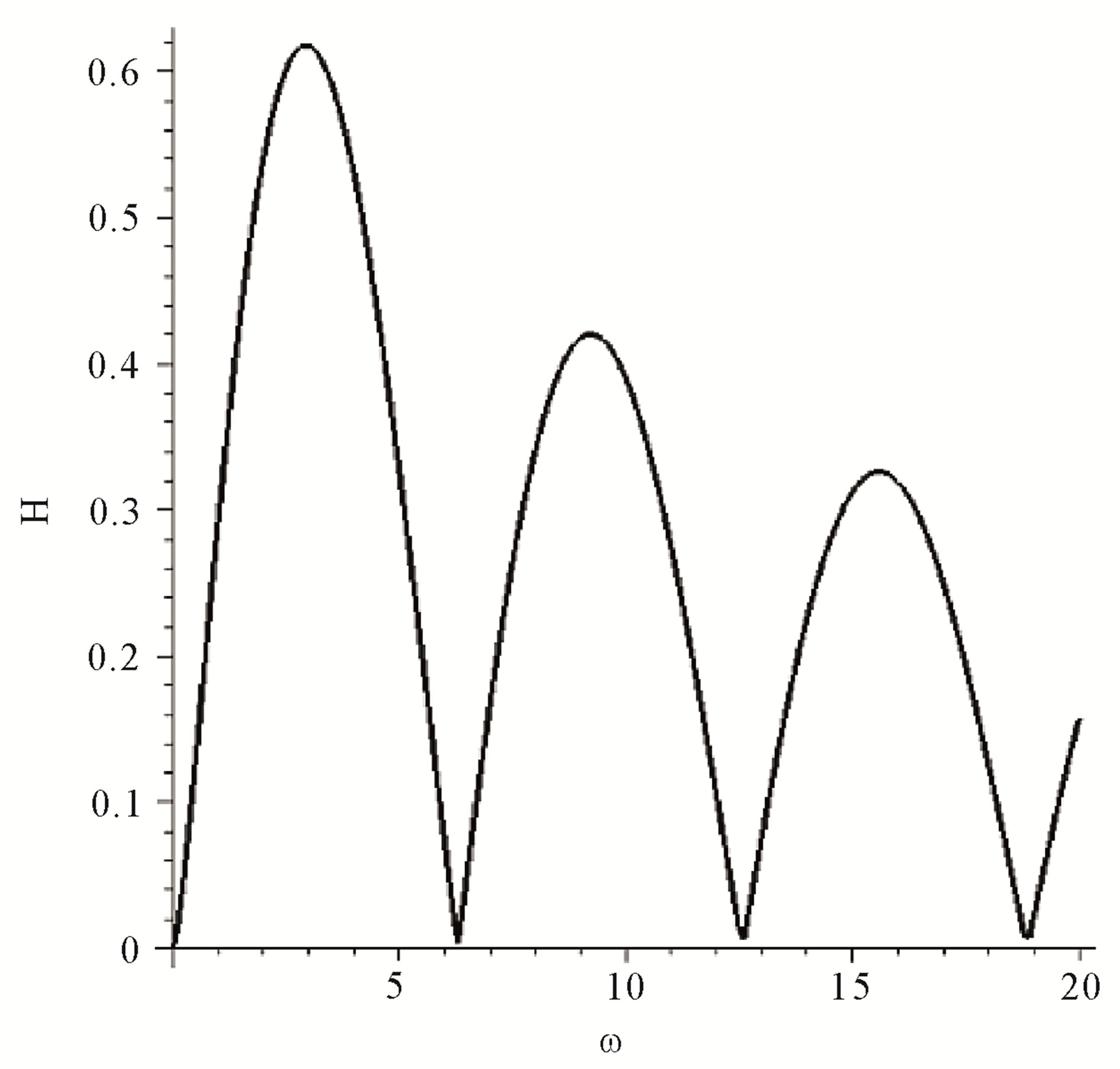
Figure 5. Frequency dependence of the magnetic field created by the tip of crack.

Figure 6. Frequency dependence of the magnetic field created by the unloading wave.
for a large and slow crack with L » 1 m and Vcr » 1.5 km/s the corresponding frequencies will be ft,1 » 720 Hz and fu » 320 Hz. Therefore, the spectrum of the field can be very wide. Because the magnetic field is registered from numerous cracks of different sizes, it is possible to conclude that the resulting field lies in LF, VLF and ELF ranges of the spectrum: VLF (very low frequencies ~ 1 - 10 kHz) at the depth of about 30 km, ELF (extremely low frequencies, ~ 3 Hz - 1 kHz) on the Earth’s surface, then they pass the atmosphere and penetrate into the ionosphere like ULF (ultra low frequencies <1 Hz) range.
Thus, obtained amplitude-frequency characteristics of the magnetic field generated by the fracturing of piezocrystals in rocks have several frequency scales. From these results one can explain some phenomena caused by seismic and volcanic activity. The main result of the calculations is that it is possible to see difference between seismic and industrial events by means of observation of the unloading wave only in the case of natural hazards. This opens a possibility to create the method of remote sensing and dividing the seismic and industrial events.
5. CONCLUSIONS
An analysis of the nonlinear transformation of the spectrum: VLF (very low frequencies ~ 1 - 10 kHz) at a depth of about 30 km , ELF (extremely low frequencies ~ 3 Hz - 1 kHz) on the Earth’s surface, then they pass the atmosphere and penetrate into the ionosphere like ULF (ultra low frequencies < 1 Hz) range.
The nonlinear interaction of acoustic burst demonstrates additionally the importance of acoustic channel by the example of the nonlinear mechanism of the energy flow from the lithosphere into the ionosphere.
The destruction of rocks has been analyzed for cases of piezoelectric and magnetic crystals. In the both cases there exists the quasi-stationary magnetic dipole, which is the source of the magnetic field (and the source of electromagnetic radiation in the far zone, too). Such a dipole is created by the motion of the apex of the crack and depends on the specific crystalline symmetry that determines its piezoproperties. The field has several maxima as a function of the frequency. These maxima are determined by the crystal size and the velocity of the crack and are located in LF, VLF and ELF ranges of the spectrum. The values of the magnetization vector and the corresponding magnetization current are estimated. The value of magnetization current for a typical piezoelectric like quartz is smaller (but comparable) than one for a typical piezomagnetic material. The basic conclusion of the calculation is that it is possible to see the difference between natural seismic and industrial events by means of observation of the unloading wave. The unloading wave is absent in the case of non-natural events. This opens a possibility to create the method of remote sensing and dividing the seismic and industrial events.
6. ACKNOWLEDGEMENTS
Authors thank SEP (PROMEP)-CONACyT for the support of our work.
REFERENCES
- Galperin, Yu.I., Gladyshev, V.A., Jorjio, N.V., Kovrazhkin, R.A., Lissakov, Yu.V., Maslov, V.D., Nikolaenko, L.M., Sagdeev, R.Z., Molchanov, O.A., Mogilevsky, M.M., Alperovich, L.S., Gokhberg, M.B., Ivanov, E.A., Pokhotelov, O.A., Beghin, C., Berthelier, J.J., Bosqued, J.-M., and Reme, H. (1985) Alfvén wave excited in the middle-latitude mag- netosphere by a large-scale acoustic wave propagating in lower ionosphere. Izvestiya, Physics of the Solid Earth, 21, 88-98.
- Warwick, J.W. (1963) Radio astronomical and satellite studies of the atmosphere. North-Holland, Amsterdam.
- Gokhberg, M., Morgounov, V. and Pokhotelov, O. (1995) Earthquake prediction: Seismo-electromagnetic phenomena. Gordon and Breach, London.
- Tarantsev, A. and Birfeld, Ya. (1973) The phenomenon of the action of the Earth’s seismicity on the ionosphere through the acoustic waves, September 1963. CNIIPII Publication, Moscow.
- Kotsarenko, N., Enriquez, R.P. and Koshevaya, S. (1997) Excitation of plasma waves in the ionosphere caused by atmospheric acoustic waves. Astrophysics and Space Science, 246, 211-217. doi:10.1007/BF00645641
- Surkov, V.V., Molchanov, O.A. and Hayakawa, M. (2003) Pre-earthquake ULF electromagnetic perturbations as a result of inductive seismo-magnetic phenomena during microfracturing. Journal of Atmospheric and Solar-Terrestrial Physics, 65, 31-46. doi:10.1016/S1364-6826(02)00117-7
- Makarets, M.V., Koshevaya, S.V. and Gernets, A.A. (2002) Electromagnetic emission caused by the fracturing of piezoelectrics in rocks. Physica Scripta, 65, 268-272. doi:10.1238/Physica.Regular.065a00268
- Khavroshkin, O.B., Tsyplakov, V.V. and Berezhnoi, A.A. (2001) Modification of the Moon’s microwave radiation by the fall of lunar prospector. Doklady Earth Sciences, 376, 90-92.
- Musatenko, S.I., Kurochka, E.V., Aslanyan, A.M., Borovkov, O.V., Gulyan, A.G., Ivchenko, V.N., Kotsarenko, A.N., Slipchenko A.S., Margorin O.K., and Nabatov, A.S. (1997) Fluctuations of Jupiter radio emission at 3.6 cm due to the impact of the fragments of Comet Shoemaker-Levy. Kinematika i Fizika Nebesnykh Tel (Kinematics and Physics of Celestial Bodies), 13, 64-73.
- Berezhnoy, A.A., Bervalds, E., Khavroshkin, O.B., Kovalenko, A.V., Ozolins, G., Paupere, M., Smirnov and G.T., Tsyplakov, V.V. (2002) Radio observations of the Moon during activity periods of the Leonid and Lyrid meteor streams. Baltic Astronomy, 11, 507-527.
- Rudenko, O. (1995) Nonlinear sawtooth-shaped waves. Physics-Uspekhi, 38, 965-989. doi:10.1070/PU1995v038n09ABEH000104
- Koshevaya, S., Grimalsky, V., Makarets, N., Kotsarenko, A., Siquieros-Alatorre, J., Perez-Enriquez, R. and JuarezRomero, D. (2008) Electromagnetic emission from Magnetite plate cracking under seismic processes. Advances in Geosciences, 14, 25-28. doi:10.5194/adgeo-14-25-2008
- Gernets, A.A., Makarets, M.V., Koshevaya, S.V., Grimalsky, V.V., Juarez-Romero, D. and Kotsarenko, A.N. (2004) Electromagnetic emission caused by the fracturing of piezoelectric crystals with an arbitrarily oriented moving crack. Physics and Chemistry of the Earth, 29, 463- 472. doi:10.1016/j.pce.2003.12.006
- Vainshtein, V.K., Ed. (1981) Modern crystallography. Nauka, Moscow.