Engineering
Vol. 4 No. 10 (2012) , Article ID: 23353 , 4 pages DOI:10.4236/eng.2012.410083
Using Stochastic Colored Petri Nets for Designing Multi-Purpose Plants
1Department of Industrial Engineering, Yazd University, Yazd, Iran
2Department of Economics, Yazd Branch, Islamic Azad University, Yazd, Iran
Email: *hhn@yazduni.ac.ir, ali.sadri@gmail.com
Received July 24, 2012; revised August 26, 2012; accepted September 6, 2012
Keywords: Multi-Purpose Plant; Stochastic Colored Petri Net; Simulation
ABSTRACT
Designing of a multi-purpose plant as one of the well-known manufacturing systems is more challenging than other manufacturing systems. This paper applies a stochastic colored Petri net (CPN) to design and analyze multi-purpose plants. A simple approach is proposed to determine the utilization of shared resources and to reduce the equipment’s idle times. Three scenarios are presented to describe the proposed model. Generally, according to desire of a decision maker, different scenarios can be considered in the model to achieve to the expected design or plant configuration. The main characteristics of the proposed model are flexibility, the easiness of practical application and the simulation of the model in an easy way.
1. Introduction
In multi-purpose plant, various products can be produced by sharing the available resources such as equipment, raw material, labor, intermediates, and utilities over the time horizon of planning [1,2]. In fact, in multi-purpose plant, each product follows its own separate processing sequence by using the available factor of production [3]. These types of the production plant are very appropriately encountering with fluctuated market demands of various products. Because of the flexible nature of multi- purpose plant, designing such a plant is more challenging and sophisticated than other manufacturing systems that produce a single product. Design problem is defined as finding the best combination of the available resources to be installed and the task operation [2]. Therefore, to utilize the common resources efficiently and effectively, it is necessary to design the plant in a rational way to achieve equipment’s idle times reduction and consequently operational cost of the plant reduction.
Because of its graphical nature, simple mathematical support, clearness and compactness to represent complex and dynamic behavior, Petri net (PN) has been extensively applied in model, analysis and control of production systems [4]. Also, colored Petri nets as an extension of ordinary Petri nets belong to the area of the discrete event systems [5]. To model the multi-purpose plant, as a discrete event system and due to probabilistic/stochastic nature of operational time of equipment’s, a stochastic colored Petri net is selected for modeling the multi-purpose plant.
The main aim of this paper is to propose a simple approach to determine the utilization of the common equipment’s and other factor of production and to reduce the equipment’s idle times based on stochastic colored Petri net in the design of a multi-purpose plant.
The rest of this paper is organized as follows: Section 2 surveys on relevant literature and describes the research motivation. Section 3 describes the principles of the ordinary and colored Petri nets. Section 4 presents the colored Petri net model for a specific multi-purpose plant. A numerical example and simulation results are given in Section 5, and finally, the conclusion is presented in Section 6.
2. Literature Review and Research Motivation
An increasingly exploration in multi-purpose processing has been obvious in recent years. A comprehensive review of the multi-purpose plant design can be found in Barbosa-Povoa [2]. Castro et al. [6] developed two types of mathematical formulation based on Resource-Task Network (RTN) representation-mixed-integer non-linear programs and mixed-integer linear programs—according to the types of tasks and objective functions. Heo et al. [7] proposed the cyclic scheduling, planning and design of the multi-purpose plant using a non-linear program. Bernal-Haro et al. [8] presented a multi-objective model for designing a multi-purpose plant and developed a genetic algorithm (GA) for solving the design problem. Multi-cell modeling using colored Petri Nets applied to planar cell polarity proposed by Gao et al. [9] They presented an approach to model at different spatial scales, applied to a tissue comprising multiple hexagonally packed cells in a honeycomb formation in order to describe the phenomenon of Planar Cell Polarity (PCP). They presented an approach to model this phenomenon by applying colored Petri Nets (CPN). The aim was to discover the basic principles of implementing CPN to model a multi-cellular system with a hierarchical structure while keeping the model mathematically tractable.
Lin and Floudas [10] proposed a continuous formulation based on State-Task Network (STN) to address the design of the best choice of the main equipment units and associated schedule. Cavin et al. [11] developed a multiobjective mathematical model that takes safety, technical limitation and short term availability of units into consideration. They proposed a Tabu Search (TS) to determine the number of equipment units to be installed. Dynamic modeling approach to simulate vehicle routing and actual traffic information using Timed Colored Petri Nets (TCNPs) proposed by Cao and Xing [12]. They considered that the traffic conditions are variable and the location of the vehicle changes continuously, how to efficiently find a real-time optimal route based on the traffic level on the roads poses significant design challenges. They used simulation method and found that the simulation results will provide timesaving route guidance reflecting real-time varying traffic conditions. Cavin et al. [3] developed a method that optimizes the design of a single chemical process to be implemented in a multipurpose plant with considering the connectivity constraint. They proposed a Tabu Search to solve the presented multi-objective combinatorial non-linear problem. The authors apply the algorithm on three cases. The first case study was compared with an optimal solution while for the others, no optimal solutions were obtained. Pinto et al. [13] used the RTN representation to the design of multi-purpose plant. In their proposed model, the equipment choice as well as plant topology and associated schedule were defined simultaneously. Pan et al. [14] presented a precedence-based mixed integer linear programming (MILP) formulation for short-term scheduling of multi-purpose batch plant. In the proposed model, multi-purpose plants were described with the modified STN approach. The authors developed an iterative procedure to determine the appropriate number of batch that leads to a global optimal solution. Pinto et al. [15] studied the design of multi-purpose plant considering economic aspects. The model was offered the optimal solution by multi-objective optimization defining the efficient frontier. The model was presented the identification of range of a range of optimal plant topologies, facilities design and storage policies that minimize the total cost as well as maximize total revenue of the system.
Also, because of its characteristics that will be described in the Section 3, Petri net and its extensions such as colored PN, timed PN, stochastic PN and stochastic colored PN have been widely applied to the modeling, analysis and control of the manufacturing systems [4]. A thorough review on PNs and their applications in manufacturing systems can be found in Tuysuz and Kahraman [16].
According to the above literature review, it is found that none of the researchers have applied the stochastic colored Petri net to model the multi-purpose plant. This is our major motivation for this paper.
3. Petri Net Concepts
This section gives a brief introduction to the Petri net found in the literature.
3.1. Ordinary Petri Net
The Petri net theory was designed by Carl Adam Petri in 1962 in his Ph.D. Thesis. At the end of 60s and beginning of 70s, it has been developed in MIT as we know today [17]. Petri nets are the graphical and mathematical tool for describing systems that are characterized as being concurrent, asynchronous, distributed, parallel and nondeterministic [17]. Petri net has a function similar to flowcharts, block diagrams, logical trees and networks.
A marked Petri net  is a pair and
  is a 4-tuple which is called PN structure, where:
1)  is a finite set of places that illustrated by circles or ellipses.
2)  is a finite set of transitions that illustrated by bars or rectangular boxes,
  and
and .
.
3) 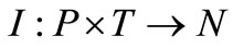 is a set of directed arc namely input function that indicates flow relation from P to T.
4)  is a set of directed arc namely output function that indicates flow relation from T to P.
5) 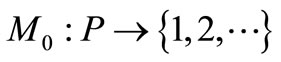 is the initial marking whose ith component represents the number of tokens in the ith place that illustrated by dots in associated places.
A marked PN and its elements are depicted in Figure 1.
In PNs, transitions represent events, actions or processes, and places represent conditions, states or buffers. Also, tokens are used in PNs to simulate the dynamic behavior and concurrent activities of systems [16,17].
The behavior many systems can be described in terms of system state and their actions. Due to simulate the
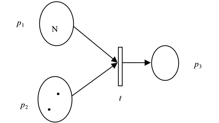
Figure 1. A marked ordinary PN.
dynamic behavior of a system, a state or marking in a marked Petri net is changed regarding to the following transition (firing) rules [17]:
1) A transition t is called enable, if each input place p of t has at least  tokens, where
  is the weight of the arc from p to t.
2) A firing of an enabled transition t removes 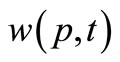 tokens from input places and adds
  tokens to the output place.
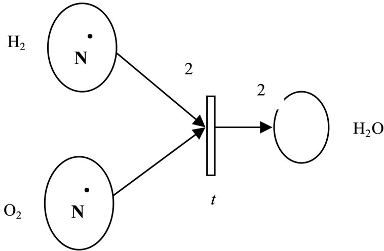
A typical example Petri net using the well-known chemical reaction is illustrated in Figure 2. Figures 2(a) and (b) depicted the marking before and after firing the enabled transition t, respectively.
More details and discussion about basic concepts of PNs, are presented by Murata [17,18].
3.2. Colored Petri Net (CPN)
A major limitation of the ordinary PN is the increasing quantity of places and transitions to represent complex systems that occur in the real world [19]. Thus, modeling and analyzing the real world systems is troublesome to do. To succeed in facing this difficulty, colored Petri net has been introduced by Jensen [20]. In the ordinary Petri net, if the tokens are recognizable, it is called CPN. Colored Petri net is very suitable for modeling the discrete event systems.
According to formal definition, a CPN model is a 9-tuple 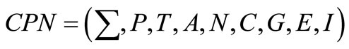 where [21]:
(1)  is a finite set of non-empty types, called color sets.
(2) P: is a finite set of places.
(3) T: is a finite set of transitions.
(4) A: is a finite set of arc such that .
.
(5) N: is a node function.
(6)  is a color function.
(7) G: is a guard function. It is defined from T.
(8) E: is an arc function. It is defined from A.
(9) I: is a initialization function. It is defined from P.
The sets of  and
and  are similar to that of described for ordinary Petri nets. C maps every place in the net, including them in a color set. G maps all the transi-
 (a)
(a) (b)
(b)
Figure 2. Example of transition firing of H2O generation (a) Before firing (b) After firing [17].
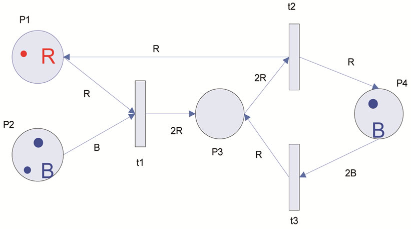
tions on the net, moderating the flow of tokens according to Boolean expression. E maps each arc on the net, associating them to a compatible expression with the possible color set. Ultimately, I maps the places on the net, associating them on the existent multi-sets [19]. An example of CPN and its firing are shown in Figure 3.
The place p1 has a token of color 1 (red), and the place  has two tokens of color 2 (blue). Transition
  is enable (capable to fire), because
 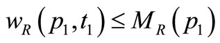 and
and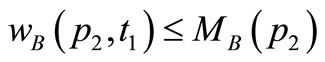 , where
  is the red color weight of the arc from
  to
to ,
,  is the blue color weight of the arc from
  to
to ,
,  is the number of red tokens in the place
  and finally
  is the number of blue tokens in the place
 . So, firing of
  will remove a token of color 1 (red) from
  and a token of color 2 (blue) from
  and will add two tokens of color 1 (red) to the
  (because
 ).
).
It should be noted that the data association to the tokens makes the model more compact.
The concept of time was not considered in preliminary ordinary Petri nets [16], but for many practical applications such as manufacturing systems modeling, the addition of time is indispensable. In PNs and its extensions, time often assigned to transitions. If we consider a func-
 (a)
(a)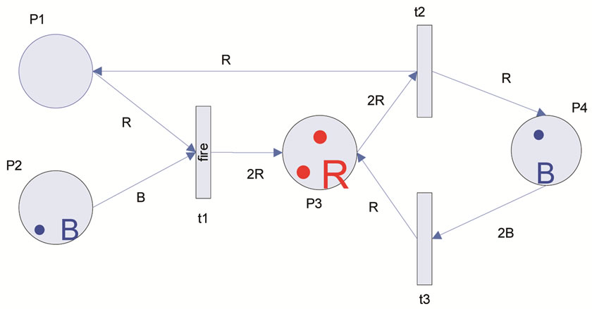 (b)
(b)
Figure 3. Example of transition firing in CPN (a) Before firing; (b) After firing.
tion  that associates a transition firing ratio
  in each transition
 , a stochastic Petri net is obtained.
4. Colored Petri Net for a Simple Multi-Purpose Plant
Regarding to aforesaid definition, a multi-purpose plant basically consists of a set of shared resources for producing a variety of products, according to client demand. Our target in this paper is to determine the utilization of the common equipment’s and to recommend the scenarios to reduce the idle times.
A simple multi-purpose plant is given in Figure 4, in State-Task Network representation, which is selected from Barbosa-Povoa et al. [1].
The presented plant is designed to produce two main products S7 and S8 using three tasks (T1 to T3). Our multi-purpose plant consists of three machines (M1 to M3) and two Robots (R1 and R2). R1 is assigned to loading and unloading workpieces, S1 and S2 on both machines M1 and M2. R2 is dedicated to loading and unloading processed parts (S3 and S4) on M3. A buffer with capacity of two intermediate parts between the machines M1 and M2 is considered. There are two incomeing conveyers for S1 and S2, separately. Also, there are three pallets for incoming parts S1, and S2. After delivering a final product S4 and S5, respectively, assigned pallet are automatically defixtured and then fixtured with the new parts S2 and S1, respectively and ultimately re-
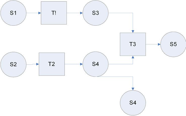
Figure 4. State-task network representation for producing two products S4 and S5 [22].
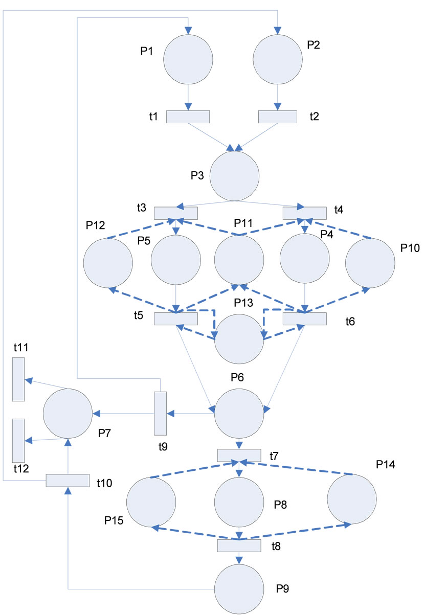
Figure 5. The CPN model of the simple multi-purpose plant.
turn to the related incoming conveyers.
The CPN of pre mentioned multi-purpose plant is shown in Figure 5.
The type workpiece presents the parts (S1 and S2) to be processed for producing two products S4 and S5. Since that S1 is processed to produce S4 for simplicity S1 and S4 are renamed to A and also, S2 and S5 are renamed to B. we mean the part A is used to produce the product A and the part B is used to produce the product B (the part B has more weight in producing the product B than the part A). The type pallet presents an empty pallet
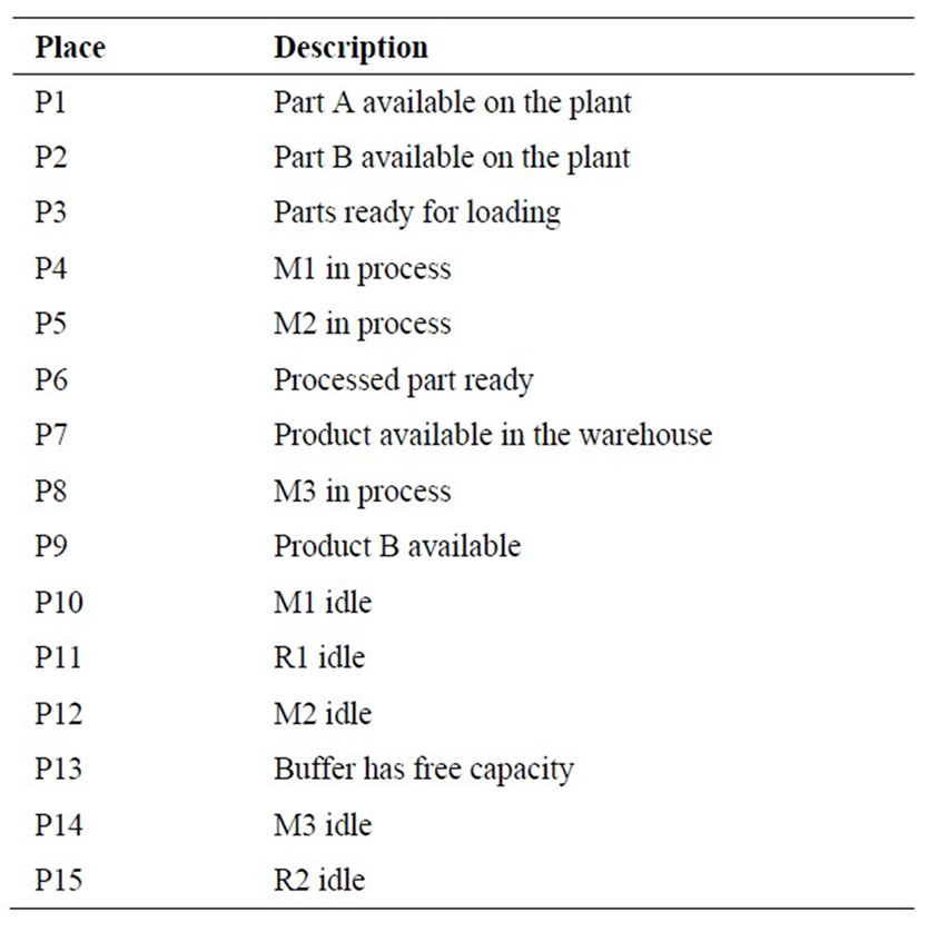
Table 1. Description of places used in the proposed CPN.
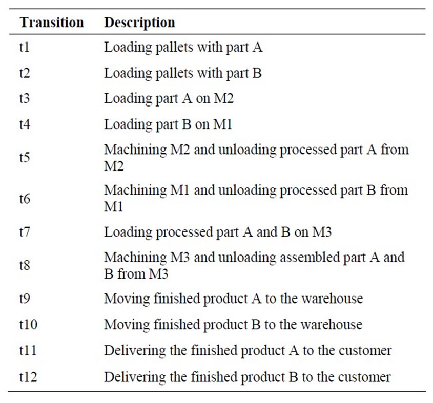
Table 2. Description of transitions used in the proposed CPN.
after delivering the finished product.
Places and transitions of the CPN model are summarized in Tables 1 and 2, respectively.
In the propose CPN model, transition t1 has one input place P1 and one output place P3. A token in the place P1 denotes that at least one part A is available in the plant. After firing t1, P3 contains one part A. Similarly for the transition t2, after firing t2, P2 contains one part B. Transition t3 has three input places P3, p11 and p12 and one output place P5. For enabling the t3, R1 and M2 must be idle and part B must be available. After firing t3, P5 has one token type B. This condition is the same for t4. Transition t5 has two input places P5 and P13 and four output places P6, P11, P12 and P13. After firing t5, processed part A is available in the P6, P13 contains one token and half of buffer capacity is occupied and M2 and R1 are idled. Similarly, for transition t6, after firing the transition, processed part B is ready in the P6, buffer capacity is occupied and M1 and R1 are idled. Transition t7 has three input places P6, P14 and P15 and one output place P8. For enabling the transition t7, processed part A and B must be ready and M3 and R2 must be idled. Transition t8 has one input place P8 and three output places P9, P14 and P15. After firing the transition t8, M3 and R2 are idled and product B is available. Transition t9 has one input place P6 and two output places P1 and P7. After firing t9, one empty pallet is filled by part A and one finished product A is available in the warehouse. Similarly, for t10, after firing this transition, one empty pallet is filled by part B and one finished product B is available in the warehouse.
5. Numerical Example and Simulation Result
In this section, a fictitious problem is considered. For examining the behavior of the modeled system, CPNTools as a simulation software is used. This software was developed by Aarhus University for modeling, simulation and analysis of CPN. CPNTools can be obtained via the website http://cpntools.org. Generally, by making simulation process of the CPN model, it is possible to examine different scenarios and explore the behavior of the system. In fact, the simulation process produces a way to investigate different scenarios and to check whether the model works as expected. More information about CPN modeling language and the way of construction, simulation and performance analysis the CPN models by CPNTools is presented by Jensen et al. [21].
It should be noted that because of probabilistic/stochastic nature of the firing rate in the real world, an exponentially distributed random variable is assigned to each transition.
Transition firing rate of the made-up example is given in Table 3.
With the parameters given in the Table 3 and assumptions of the considered plant that were described in the Section 4, the average of equipment’s idle times (in 480 minutes) that obtained from ten simulated models, are summarized in Table 4. This case is called as scenario 1.
In the scenario 1, the utilization of R2 is very low. Therefore, under the new scenario called scenario 2, the unloading function of the R1 is dedicated to the R2. The result of this case of simulation is given in the Table 5.
Concerning the scenario 2, it can be noticed that the idle times of R2, M1, M2 and M3 were reduced, signifi-
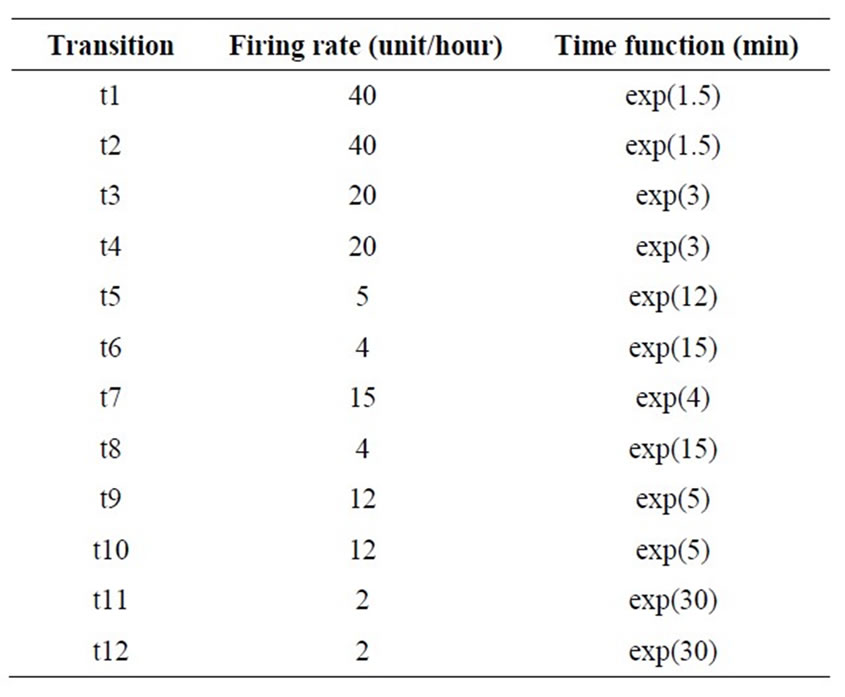
Table 3. Transition firing rates and time functions of the made-up example.
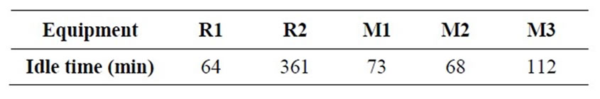
Table 4. Result of simulation of the scenario 1.
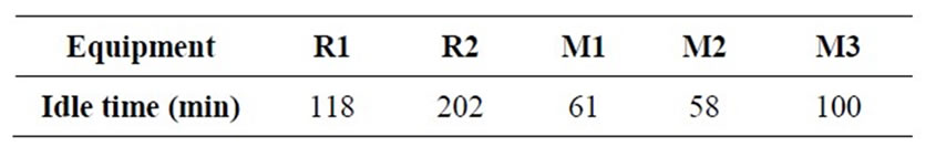
Table 5. Result of simulation of the scenario 2.
cantly.
Here, we consider another scenario named as scenario 3 that in which larger space for buffer is assigned than the current condition. Considered space has the capacity of four intermediate part between two machines M1 and M2. The equipment’s idle times under this scenario and take the assumption of scenario 2 into consideration are shown in Table 6.
In this case, by increasing the capacity of buffer space from 2 to 4, all equipments’ idle times were decreased. Figure 6 gives the comparison results of equipment’s idle times of three examined scenarios. It is obvious that scenario 3 is significantly better than others.
Other scenarios can be examined, for example, we can increase the number of pallets, or we can improve operational time of equipment’s (if possible) and then simulate the model and achieve to the expected condition.
6. Conclusion
Due to flexible nature of multi-purpose plant, designing these types of plants is very complex. This study proposed a stochastic colored Petri net for modeling and analyzing the multi-purpose plant. Advantages of the presented model can be highlighted as follows: flexibility of the model, simplicity and easiness of practical appli-
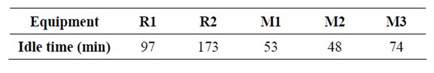
Table 6. Result of simulation of the scenario 3.
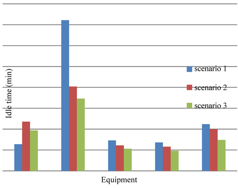
Figure 6. Comparison result of three scenarios.
cation and simulation the model in an easy way. In this paper, we supposed three scenarios and observed the result of simulation. With regard to desire of a decision maker, by sensitivity analysis and generating different scenarios, it is possible to achieve to the expected condition. In this study, we neglected economic/financial consideration of each scenario. For further research, considering the economic aspects is recommended.
REFERENCES
- A. P. Barbosa-Povoa, T. Pinto and A. Q. Novais, “Optimal Design of Heat-Integrated Multipurpose Batch Facilities: A Mixed Integer Mathematical Formulation,” Computers & Chemical Engineering, Vol. 25, No. 4-6, 2001, pp. 547-559. doi:10.1016/S0098-1354(01)00634-2
- A. P. Barbosa-Povoa, “A Critical Review on the Design and Retrofit of Batch Plants,” Computers & Chemical Engineering, Vol. 31, No. 7, 2007, pp. 833-855. doi:10.1016/j.compchemeng.2006.08.003
- L. Cavin, U. Fisher, F. Glover and K. Hungerbuhler, “Multi-Objective Process Design in Multipurpose Batch Plants Using a Tabu Search Optimization Algorithm,” Computers & Chemical Engineering, Vol. 28, No. 4, 2004, pp. 459-478. doi:10.1016/j.compchemeng.2003.07.002
- E. L. Mellado, N. V. Paredes and H. A. Canepa, “Modeling of Batch Production Systems Using Petri Nets with Dynamic Tokens,” Mathematics and Computers in Simulation, Vol. 67, No. 6, 2005, pp. 541-558. doi:10.1016/j.matcom.2004.07.005
- A. Kovacs, E. Nemeth and K. M. Hangos, “Modeling and Optimization of Runway Traffic Flow Using Colored Petri Nets,” 5th International Conference on Control and Automation, Budapest, 26-29 June 2005, pp. 881-886. doi:10.1109/ICCA.2005.1528246
- P. M. Castro, A. P. Barbosa-Povoa and A. Q. Novais, “Simultaneous Design and Scheduling of Multipurpose Plants Using Resource Task Network Based Continuous-Time Formulations,” Industrial & Engineering Chemistry Research, Vol. 44, No. 2, 2005, pp. 343-357. doi:10.1021/ie049817h
- S. K. Heo, K. H. Lee, H. K. Lee, I. B. Lee and J. H. Park, “A New Algorithm for Cyclic Scheduling and Design of Multipurpose Batch Plants,” Industrial & Engineering Chemistry Research, Vol. 42, No. 4, 2003, pp. 836-846. doi:10.1021/ie020308u
- L. Bernal-Haro, C. Azzaro-Pantel, L. Pibouleau and S. Domenech, “Multiobjective Batch Plant Design: A TwoStage Methodology. 1. Development of a Design-Oriented Discrete-Event Simulation Model,” Industrial & Engineering Chemistry Research, Vol. 41, No. 23, 2002, pp. 5727-5742. doi:10.1021/ie010646f
- Q. Gao, F. Liu, D. Tree and D. Gilbert, “Multi-Cell Modelling Using Coloured Petri Nets Applied to Planar Cell Polarity,” Proceedings of the 2nd International Workshop on Biological Processes & Petri Nets, Vol. 724, 2011, pp. 135-150. http://ceur-ws.org/
- X. Lin and C. A. Floudas, “Design, Synthesis and Scheduling of Multipurpose Batch Plants via an Effective Ontinuous-Time Formulation,” Computers & Chemical Engineering, Vol. 25, No. 4-6, 2001, pp. 665-674. doi:10.1016/S0098-1354(01)00663-9
- L. Cavin, U. Fisher, A. Mosait and K. Hungerbuhler, “Batch Process Optimization in a Multipurpose Plant Using Tabu Search with a Design-Space Diversification,” Computers & Chemical Engineering, Vol. 29, No. 8, 2005, pp. 1770-1786. doi:10.1016/j.compchemeng.2005.02.039
- Y. Cao and P. Xing, “Dynamic Simulation of Vehicle Routing Using Timed Colored Petri Nets,” Advances in Location-Based Services, 2012, pp. 119-129.
- T. R. Pinto, A. P. Barbosa-Povoa and A. Q. Novais, “Multi-Objective Design of Multipurpose Batch Facilities Using Economic Assessments,” Computer Aided Chemical Engineering, Vol. 25, 2008, pp. 271-276. doi:10.1016/S1570-7946(08)80050-8
- M. Pan, Y. Qian and X. Li, “A Novel Precedence-Based and Heuristic Approach for Short-Term Scheduling of Multipurpose Batch Plants,” Chemical Engineering Science, Vol. 63, No. 17, 2008, pp. 4313-4332. doi:10.1016/j.ces.2008.05.046
- T. Pinto, A. P. Barbosa-Povoa and A. Q. Novais, “Optimal Design and Retrofit of Batch Plants with Periodic Mode of Operation,” Computers & Chemical Engineering, Vol. 29, No. 6, 2005, pp. 1293-1303. doi:10.1016/j.compchemeng.2005.02.001
- F. Tuysuz and C. Kahraman, “Modeling a Flexible Manufacturing Cell Using Stochastic Petri Nets with Fuzzy Parameters,” Expert Systems with Applications, Vol. 37, No. 5, 2010, pp. 3910-3920. doi:10.1016/j.eswa.2009.11.026
- T. Murata, “Petri Nets: Properties, Analysis and Applications,” Proceedings of IEEE, Vol. 77, No. 4, 1989, pp. 541-580. doi:10.1109/5.24143
- G. Balbo, J. Desel, K. Jensen, W. Reisig, G. Rozenberg, and M. Silva, “Introductory Tutorial Petri Nets,” 21st International Conference on Application and Theory of Petri Nets, Aurhus, 2000.
- B. A. Prata, E. F. Nobre Junior and G. C. Barroso, “A Stochastic Colored Petri Net Model to Allocation Equipment’s for Earth Moving Operations,” ITcon, Vol. 13, 2008, pp. 476-490.
- K. Jensen, “Colored Petri Nets and the Invariant Method,” Theoretical Computer Science, Vol. 14, No. 3, 1981, pp. 317-336. doi:10.1016/0304-3975(81)90049-9
- K. Jensen, “Coloured Petri Nets: Basic Concepts, Analysis Methods and Practical Use, Volume 1: Basic Concepts,” Springler-Verlag, Berlin, 1992.
- K. Jensen, L. M. Kristensen and L. Wells, “Colored Petri Nets and CPN Tools for Modeling and Validation of Concurrent Systems,” International Journal on Software Tools for Technology Transfer, Vol. 9, No. 2, 2007, pp. 213-254.
NOTES
*Corresponding author.