Intelligent Control and Automation
Vol. 3 No. 3 (2012) , Article ID: 22051 , 12 pages DOI:10.4236/ica.2012.33030
Robust H∞ Controller for High Precision Positioning System, Design, Analysis, and Implementation
1Mechatronics Engineering Department, International Islamic University Malaysia, Kuala Lumpur, Malaysia
2Control and System Department, University of Technology, Baghdad, Iraq
3Electrical Engineering Department, Institute of Technology, Baghdad, Iraq
Email: smraafat@uotechnology.edu.iq
Received May 21, 2012; revised July 11, 2012; accepted July 18, 2012
Keywords: H∞ Mixed Sensitivity; Integral-H∞ Control; Two-Degree-of-Freedom 2 DOF H∞ Controller; Uncertainties; v-Gap Metric
ABSTRACT
In this paper, a systematic robust control design and analysis for a single axis precise positioner is presented. The effects of uncertainties on closed-loop stability and performance are considered in the H∞ robust controllers design. v-gap metric is utilized to validate the intelligently estimated uncertainty. The robust controllers are formulated within the framework of the standard H∞ mixed sensitivity optimization problem. Furthermore, a specially designed integral-H∞ and two-degree-of-freedom 2 DOF H∞ controllers are developed to provide improved robust performance and resolution properties. It is shown that the proposed design schemes are very effective for robust control and precise tracking performance of the servo positioning system.
1. Introduction
High precision motion control has become an essential requirement in today’s advanced manufacturing systems such as machine tools, micro-manipulators, surface mounting robots, etc. High precision motion control is first challenged by the presence of friction, as a highly complex, nonlinear phenomenon exists in almost every mechanical system involving relative motion between parts. In addition, other uncertainties which may also be regarded as parasitic effects are often present in real-world systems. These effects include: parametric uncertainty, such as parameter changes due to, for example, different operating conditions and load changes. Moreover, the growth of research in this area and the rapid increase in precise positioning applications [1-6] have imposed additional demands on precise positioning systems where the need for a higher precision at higher bandwidth, improved robust stability against different uncertainties, and large improvement tracking performance are essential requirements. The varieties of these applications with different operating conditions necessitate robust control designs to meet challenging requirements.
Therefore, some research works are developed on optimal H∞ feedback control methods for positioning systems, where uncertainties due to modelling errors, nonlinearities and disturbances can be dealt with in a systematic way, as in the following research works; standard nominal H∞ control for multi input-multi output (MIMO) [7], combined model reference and H∞ controllers [8], robust control with parametric uncertainties, using DK iteration for evaluating the control optimization problem [9], H∞ optimization and feed forward control [10], Quasi mixed  controller solved in linear matrix inequalities (LMI) environment [11], Glover-McFarlane loopshaping scheme [12], and formulation of a multi-objective 2 DOF optimal control problem in terms of LMI [13]. However, the selection of the required weighting functions for the robust controller synthesize is still a critical requirement. Moreover, precise tracking performance cannot be achieved by simple nominal H∞ controllers; meanwhile, it is not favorable to implement so complicated controller design methodology.
In order to overcome the first drawback, intelligent methods are developed to design the unstructured uncertainty (or the modeling error) weighting function for H∞ robust control synthesize. Reliable and efficient tool are obtained as in [14,15]. Further developments are achieved in previous works [16,17] using adaptive neuro-fuzzy inference system ANFIS technique. The purpose is to precisely estimate the uncertainty bound from which the necessary uncertainty weighting function can be directly obtained. The synthesized controller will make the system insensitive to the estimated uncertainties while guaranteeing a specified performance and larger stability margin of robust controllers, as measured by the v-gap metric.
However, the mixed sensitivity optimization problem does not capture important objectives such as multivariable interaction, and causes unnecessary pole-zero cancellation [18]. Therefore, it is advantageous to improve the robust performance using some practical schemes like closed loop with integral action or two-degree-offreedom 2 DOF control systems in order to improve tracking performance while maintaining stability robustness; in the former scheme the integral action will illuminate the tracking error while in the 2 DOF scheme the feedback controller is designed to meet robust stability and disturbance rejection specifications while the feed forward controller is used for robust command following. Implementation of these schemes improves precise tracking performance requirements. This cannot be achieved by a simple nominal H∞ control.
The paper presents a design procedure that considers intelligently estimated uncertainty bounds and optimized performance weighting function in H∞ robust controllers. Two different design schemes are formulated within the framework of the standard H∞ optimization problem in order to improve the tracking performance and to satisfy high resolution requirements. Stability analysis and practical implementations on a precise servo positioning system prove the validity of the applied approach.
This paper is organized as follows: in Section 2, the modeling of the system and the applied robust identification method are given; this is followed by the H∞ robust control design described in Section 3. Two different control schemes are used to improve the tracking performance as presented in the experimental results of Section 4. We conclude with final observations in Section 5.
2. Modeling and Robust Identification
2.1. Modeling and Identification
The single axis feed drive system under investigation has two large inertias, i.e. a motor inertia and a table inertia, and they are connected by a ball screw. The primary sources of elasticity in the system are the ball screw, flex coupling, and bearing supports. A simplified model of the single axis positioning system is shown in Figure 1.
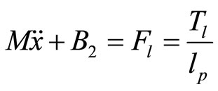
The equation of motion can be derived analytically to form the following equations:
 (1)
(1)
 (2)
(2)
where θ is the angular position, x is the measured table
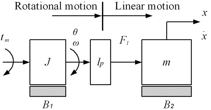
Figure 1. Simplified model of the positioning stage.
position, Tm is the motor torque, Tl is the load torque, Td is the torque disturbances, Fl is the equivalent force acting on the positioning table, J is the rotational inertia that combines the motor shaft, the coupling, and ball screw mass inertias, B1 the viscous damping contributed by the ball nut and rotational bearings, lumped together, lp is the screw pitch that serves as the transformation factor from rotational to linear motion, B2 is the mechanical damping from the linear bearings.
Theoretically, the torque Tm is proportional to the motor current I by a torque constant KT which gives the well known motor equation.
 (3)
(3)
The actual input to the system is the control voltage of the servo amplifier that supplies the current to the motor in developing an electro-mechanical torque. The motor and amplifier dynamics can be ignored if we assume that the amplifier produces instantaneously the output current to the motor. In a current mode amplifier, the output current is proportional to the input command voltage u by a constant gain Ka for a certain range of operating point. It is customary that in the industrial applications, the servomotor is driven by a high bandwidth servo amplifier so that the dominating poles are influenced by the load only. Therefore, the motor torque can be written as:
 (4)
(4)
Consequently, the equation of motion in (1) can be written as
 (5)
(5)
By regrouping the x terms in the left-hand side, the equation can be expressed as follows:
 (6)
(6)
where f(.) represents the nonlinear disturbances which include the nonlinear friction and other nonlinearities of the system.
By ignoring the effect of friction, Equation (6) can be expressed in a simplified model as follows:
 (7)
(7)
where parameter α1 and α2 are defined as:
Based on Equation (7), the transfer function of the positioning table can be written as:
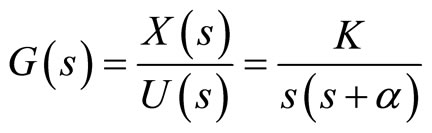 (8)
(8)
where the parameters K and α are defined as:
The linear model can approximately describe the dynamic behaviour of machine tool axis as proposed by Smith et al. [19].
Due to the simplicity of the model and assuming the input/output relationship is linear over a small region of operation about the operating point, the system parameters K and α can be identified by an off-line system identification procedure of Prediction Error Method (PEM), using experimental input/output data.
2.2. Unstructured Uncertainty Representation
Uncertainty due to neglected and unmodeled dynamics can not be exactly specified and thus, they are difficult to quantify. Nevertheless, frequency domain is well suited for this class of uncertainty. The resulted complex perturbations are normalized such that  . Unstructured additive uncertainty Wa appears in the transfer function of the plant Ga, as given in the following [20]:
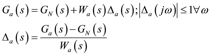 (9)
(9)
where Wa is the weighting function that describes the frequency dependent characteristics of the uncertainty and defines a neighborhood about the nominal model GN(s) inside which the actual infinite order plant resides [21]. The weight Wa is usually chosen to be large at frequencies at which the frequency response of the plant is well known, forcing Δa to be small.
2.3. Intelligent Robust Identification of Uncertainty
“Model Error Modelling” (MEM) methodology [22] is applied experimentally to prepare the required data for intelligent identification of the uncertainty bounds, as shown in Figure 2, where a special feedback adaptive network-based fuzzy inference system (FANFIS) method is developed to reduce conservativeness to minimum [17].
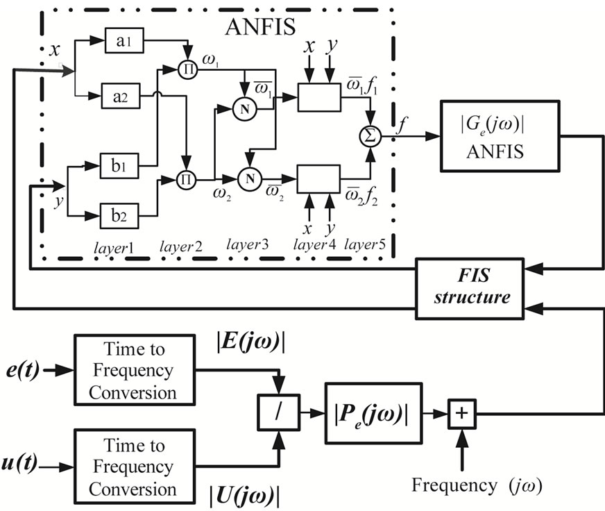
Figure 2. Intelligent model error identification, using FANFIS.
The adaptive network-based fuzzy inference system (ANFIS) is an adaptive network functionally equivalent to a first order Sugeno fuzzy inference system. The ANFIS uses a hybrid-learning rule combining back-propagation, gradient descent and a least-squares algorithm to identify and optimize the Sugeno system’s signals [23].
The mapping from input u to modelling error e is estimated as a model error frequency response |Pe(jω)|, using FANFIS of four rules [16]
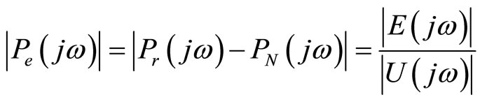 (10)
(10)
where Pr(jω) is the measured frequency response function of the actual system, and PN(jω) is the frequency response function of the nominal linear model of the system. The trained data contains elements of the model error frequency response function Pe(jω), and the previousiteration identified uncertainty bound.
The hybrid learning algorithm ANFIS is used to develop an intelligent estimation of uncertainty bound Gf [16]
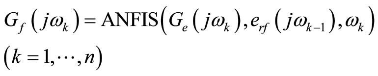 (11)
(11)
where n is the number of data samples and erf is the updating error:
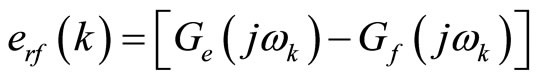 (12)
(12)
erf is utilized to enhance the search for a reduced uncertainty bound through iterative minimization procedure until some stopping criterion is met
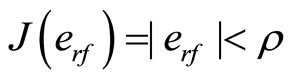 (13)
(13)
where ρ is a pre-specified very small numerical value, e.g. less than 10–3.
For validation of the intelligent uncertainty weighting function Wa the v-gap metric is implemented as [24]
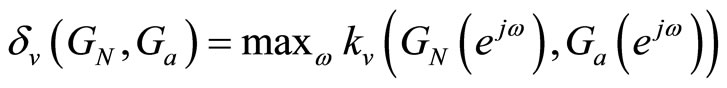
 (14)
(14)
where
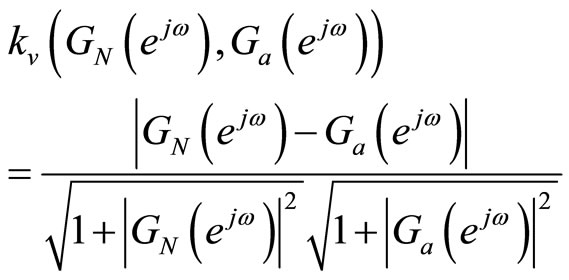 (15)
(15)
GN is the nominal plant and Ga is the perturbed plant,
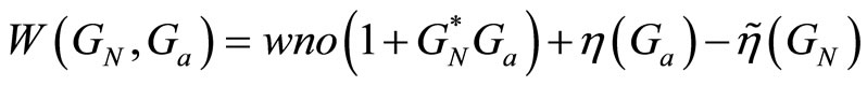
 ,
,  is the number of poles of G in the complement of the closed unit disc,
  is the number of poles of G in the complement of the opened unit disc, while wno(G) is the winding number about the origin of G(z) as z follows the unit circle pole and zero of G(z). The controller C that stabilizes GN can also stabilizes Ga if this controller lies in the controller set
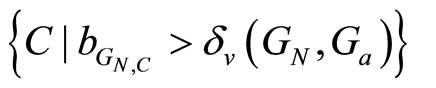 , where
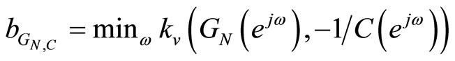 is a generalized stability margin of the stable loop [GN,C].
Then, the validated additive uncertainty weighting function (Wa), derived directly from the identified FANFIS uncertainty bound, can be used for robust control synthesis of the servo system.
3. Robust Controller Design
3.1. Nominal Controller Design
Considering the standard feedback configuration shown in Figure 3, GN is the nominal transfer function of the single axis stage comprising of the DC servo motor, the ball screw system, table, and positioning sensor. The signal y0 represents its output, the table displacement scaled by the sensor, and the signal ui represents its input given to the driver. The signal r represents the command signal that the positioning system needs to track, di represents the disturbing effect, d represents the mechanical noisethe effects of dynamics that are not incorporated in the model GN, n represents the sensor noise, and K represents the feedback control transfer function. The main objective for the design of the controller K is to make the tracking error small for the largest possible range of frequencies despite the uncertainties and the disturbances. As a result, the performance of the positioning system will be characterized by its position resolution, tracking bandwidth, and robustness to modeling uncertainties.
For a given suboptimal controller with K, the closed
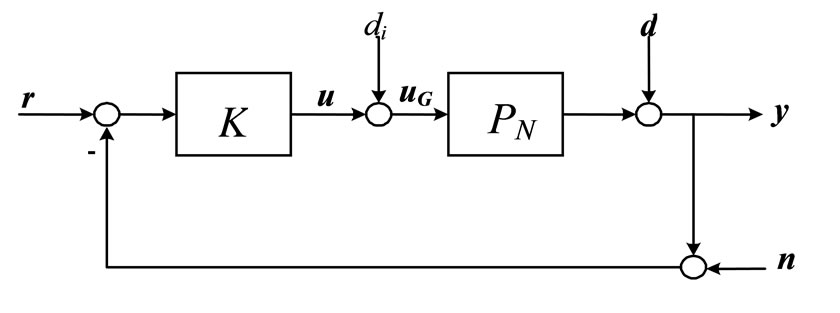
Figure 3. Standard feedback configuration.
loop signals are given by
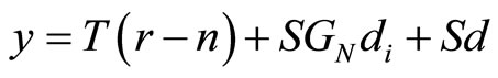 (16)
(16)
 (17)
(17)
 (18)
(18)
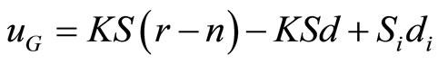 (19)
(19)
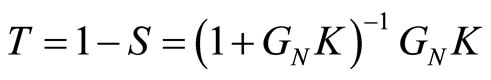
where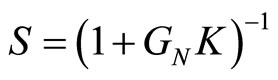 ,
,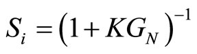 ,
,
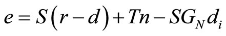
 and e is the tracking error.
The performance objectives are characterized in terms of error e in (17). Small tracking error can be achieved by designing S and T small in those frequency ranges, where the frequency contents of r, n, d and di respectively, are dominant. Robustness to modeling uncertainties can be measured by , which can be motivated by the effect of mechanical noise d. Equation (16) shows that the effects of modeling uncertainties can be made small by making S small. This requirement can be guaranteed by choosing the largest possible stability margin
  [24]. Equation (19) shows that the effects of disturbance di on the plant input can be made small by making Si small. Similarly, the resolution of the closed-loop system is determined by the effect of noise from Tn in equation (17). Small complementary sensitivity can also be guaranteed by developing large stability margin
 . Hence, it is clear that the transfer functions S and T characterize the robustness and resolution objectives in H∞ robust controller design.
In order to reflect the performance objectives into optimal control setting, the configuration of Figure 4 is considered. The main idea of this setup is to shape the closed loop transfer functions S and T with weighting functions We, Wu and Wa to achieve robust stability, disturbance rejection, and noise attenuation, and to make the closed loop response close to the target reference response r.
The closed-loop matrix transfer function from the exogenous variables  to the regulated variables
  is given by
 (20)
(20)
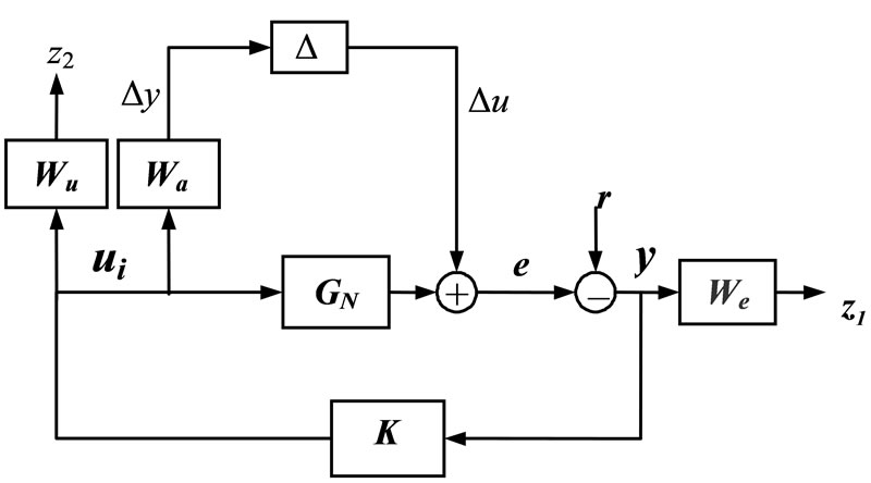
Figure 4. The entire-connection of the robustly-controlled system.
In this type of formulating the synthesized controlled system, it is necessary to treat the pole at the jω-axis first; the plant is better to preprocess with a simple bilinear pole-shifting transform [25] in order to avoid having an irrational transfer function with point discontinuities on the jω-axis at the offending jω-axis pole of the system’s nominal model.
Then, the H∞ controller transfer function is obtained as a solution to an optimization problem that incorporates the performance objectives in its cost function as
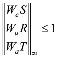 (21)
(21)
where 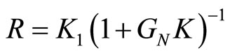 is the control sensitivity function.
The weighting function Wa is designed as described in Sections 2.2 and 2.3, the weighting function We is chosen using optimization procedure, as will be described in Section 3.2, and the weighting function for the control Wu is chosen to reduce the high frequency content of the control signal as [21]
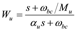 (22)
(22)
where ωbc, the bandwidth of the controller, Mu, the maximum value of the control signal are selected according to the control signal requirements, and αu is selected as a small number.
Two Riccati equations are solved in an iterative procedure to obtain the optimized solution of the H∞ robust controller [21].
3.2. Optimized Performance Weighting Function
In the H∞ robust controller design, the performance weighting function is usually adjusted to meet the requirements of improved sensitivity function. Therefore, a simple low pass filter is selected to obtain the desired performance weighting function [21]
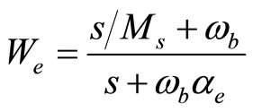 (23)
(23)
where Ms is the maximum value of the sensitivity function in all frequencies. αe is a small number to approximate the integral part of the filter with a pole near the origin, and ωb the system bandwidth.
An optimization algorithm is utilized to ensure proper selection of the weighting function parameters in terms of improved maximum singular value of the robust controller [26]. The parameters of the selected performance weighting function, We, are optimized using a Constrained Optimization (Inequalities and Bounded) technique. The optimized selection of Ms and ωb is gained by iterative evaluation of the following constrained optimization problem:
 (24)
(24)
where x is a vector of decision variables (Ms and ωb), f0 is the objective function the constrains are selected as the σmax; the maximum allowable singular value of the closed-loop controlled system and Ta; the maximum allowable tolerance between the sensitivity function and the reciprocal of the norm of the performance weighting function. fa is the allowable tolerance between the sensitivity function and the reciprocal of the norm of the performance weighting function and fs is the required singular value of the closed-loop controlled system. Ta and σmax are selected based on the performance requirements.
3.3. Implementation and Robust Stability Analysis
The hardware setup of the overall motion control scheme for the motor-table direct drive system is shown in Figure 5. The basic hardware consists of a host Pentium(R) 4 CPU2 40 GHz PC-Target, DC servo motor, and the motor-table mechanism. The currently used machine has an operating range of 225 mm. It is capable of 1 μm resolution for measurements. In the system, position feedback signal is the only sensing available, which is obtained via an incremental encoder. The developed control algorithm is implemented as Simulink blocks in MATLAB/Simulink/xPC. The controller is compiled and downloaded to the card to carry out the real-time control. The sampling interval for the real-time experiment is selected to be 1 ms in order to satisfy the requirements of convergence of the developed controller algorithm and minimum run time cost and round off error. The desired control signal is generated by the designed H∞ controller. The control signal is sent to the servo power amplifier to regulate the actuator’s position.
Based on Section 2.1, the identified model is:
 (25)
(25)
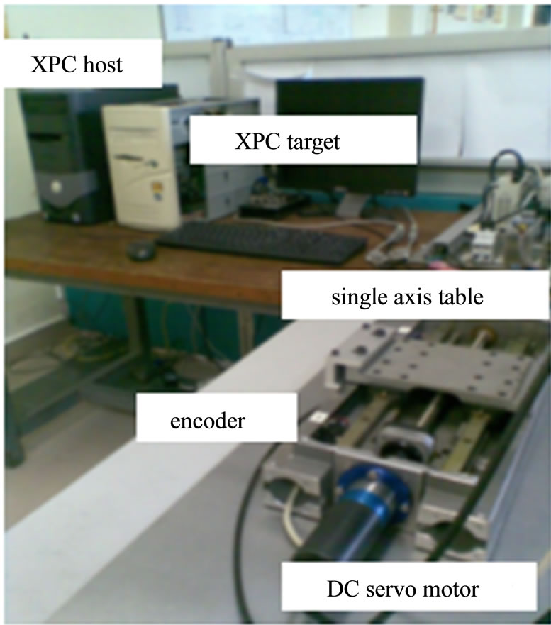
Figure 5. Experimental setup of the single-axis positioning system.
And based on Section 2.3, the evaluated second order weighting function Wa from the ANFIS uncertainty bounds is
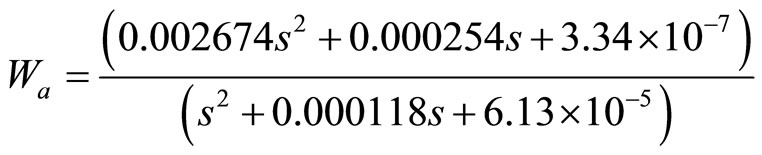 (26)
(26)
A second order model is utilized since it can provide an acceptable low v-gap metric value of 0.0027. This is in agreement with the requirement of lower order weighting function for the uncertainty bound, since the order of the H∞ controller is directly related to it. Besides, applying lower order control law is necessary in real-time application.
Suitable value for Wu that satisfies control signal and actuator limits requirements is selected as
 . (27)
The optimized performance weighting function is obtained as
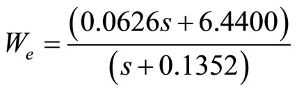 (28)
(28)
where the optimized values of Ta and σmax were obtained within 48 iterations with an objective function of 0.0225.
The H∞ robust controller is designed first using Equations (26), (27), and (28). The evaluated controller equation is
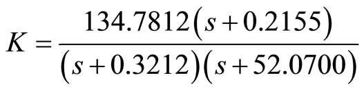 (29)
(29)
The sensitivity transfer function of the single axis po-
Figure 6. The sensitivity function of the closed-loop robustly controlled system with .
.
sitioning system is shown in Figure 6. The closed-loop controlled system is stable, less sensitivity to fast external variations, and guarantees good robustness margins.
Table 1 gives the simulation results of positioning system with the designed robust controller. It is clear that using the intelligently identified uncertainty weighting function Wa in the H∞ controller synthesis, robust stability and larger range of stable controllers is guaranteed, as indicated by the  and v-gap values, where δv is much less than
  indicating guaranteed large stability region.
The resulted µ analysis of robust stability is shown in Figure 7; the upper and lower bounds are 2.7182 and 2.7064, and the system can tolerate up to 271% of the modeled uncertainty. These results agree with the test of stability margin using Equations (14) and (15), where  equals 0.2681 indicating that the system is robustly stable to modeled uncertainties. Similarly, Figure 8 presents the µ analysis of the robust performance. The upper and lower bounds of robust performance are 1.3726 and 1.372. The achieved robust performance margin is 1.373.
4. Experimental Results
The controller as described by Equation (29) is implemented on the host PC-target through National Instrumentation BNC-2110 DAQ with 16 bit A/D and 16 bit D/A channels, using MATLAB/Simulink xPC target tools. Triangular and special sinusoidal reference signals are used, as shown in Figures 9 and 10. Table 2 presents the mean and Standard Deviations (STD)s for each of the maximum error and the measured control input signal for 10 experiments. The Root Mean Square (RMS) value of the resulted tracking error and measured control input signal are presented as well. The tracking errors are required to be further reduced for better resolution. How-
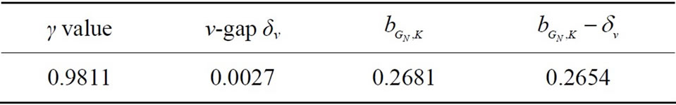
Table 1. Validation and robust stability test of Wa for robust controlled system.
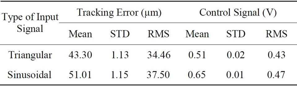
Table 2. Performance measures of the robustly controlled system using parametric and unstructured additive uncertainty representations.

Figure 7. µ plot of robust stability margins (inverted scale) of the robustly controlled system.
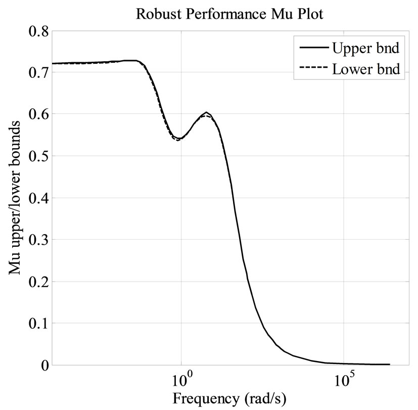
Figure 8. Robust performance µ plots of the robustly controlled system, considering additive unstructured uncertainties.
 (a)
(a) (b)
(b) (c)
(c)
Figure 9. Experimental results of applying triangular signal, using intelligent uncertainty weighting function. (a) The transient response of the closed-loop controlled system; (b) The tracking error; (c) The control signal.
ever, STD is low, indicating reliable controller. Moreover, the control signal is low with slight oscillations, as shown in Figure 10(c).
The wide range of the resulted stability control margin
 (a)
(a)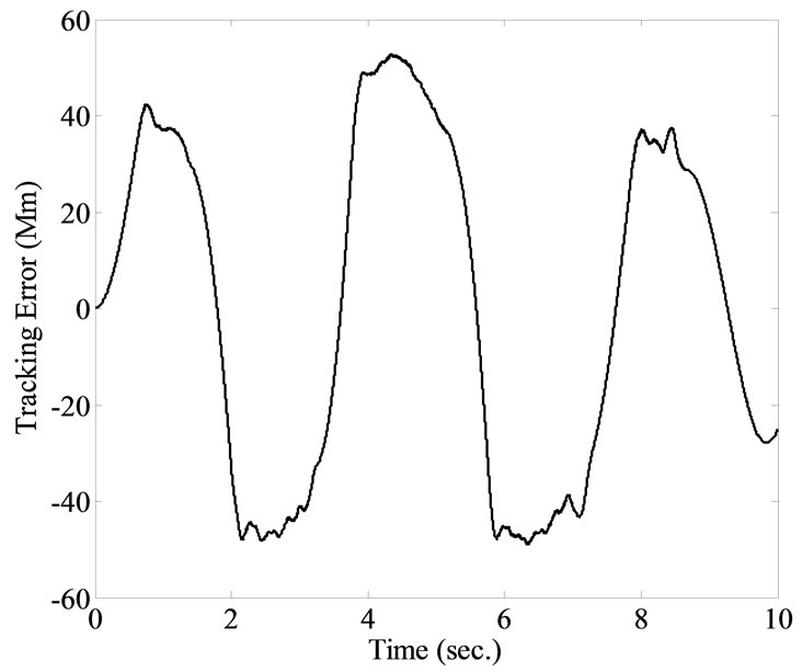 (b)
(b)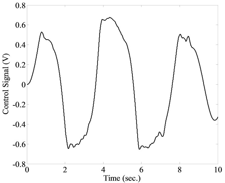 (c)
(c)
Figure 10. Experimental results of applying sinusoidal signal, using intelligent uncertainty weighting function. (a) The transient response of the closed-loop controlled system; (b) The tracking error; (c) The control signal.
and simplicity of intelligent estimation of the uncertainty provides a solid base for improvements as in the addition of integrator or the application of two stages of H∞ robust controller design, as will be presented next.
4.1. Improving Tracking Performance
Two modifications were considered for further improvement of the tracking performance in practical applications; the robust controller is augmented within a suitable control scheme to overcome the problem of unavoidable tracking error in practical implementation. These two practical schemes are integral robust control and 2 DOF H∞ robust control; which will be discussed next.
4.1.1. Integral Robust Control Scheme
For asymptotic reference tracking with zero steady state error, an integrator can be simply added to the closedloop controlled system [27]. For the designed robust controller, the tracking error can be eliminated by inclusion of integrator effect [19]. In this work, the integrator is added to the closed-loop controlled system in a modified scheme, as shown Figure 11. The effective control signal will be:
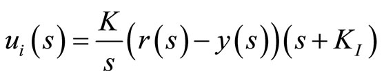 (30)
(30)
where KI > 0. The integral action improves the performance at low frequencies, and the phase advance term  maintains the gained robustness and wide bandwidth from the H∞ robust controller, providing Kmax > KI > 0, where Kmax is the maximum gain that can be applied to the integral without any violation of the robust stability condition
  where F(s) is the closedloop transfer function between the exogenous input signal r(s) and the regulated output signal y0(s).
4.1.2. 2 DOF H∞ Robust Control Scheme
The idea of a special 2 DOF H∞ scheme that shown in Figure 12, is to use a controller (K1) to achieve the internal and robust stability, disturbance rejection, etc., and to design another controller (K2) on the feed forward path to meet the tracking requirement, which minimizes the difference between the output of the overall system and that of the reference model [28].
The design problem is to find the stabilizing controller  for the augmented plant G(s), which minimizes the H∞ norm of the transfer function between the exogenous input signal r(s) and the regulated output signal y(s). The problem is easily cast into the general control configuration and solved sub-optimally in two stages using standard H∞ algorithm and γ iteration. The control signal to the shaped plant is given by
 (31)
(31)
The two stages of H∞ synthesis design procedure can be summarized as follows:
1) Design a standard H∞ controller (K1) to achieve the internal and robust stability requirements. Proper selection of stable weighting function is required in this stage. The augmented plant will be composed from the shaped
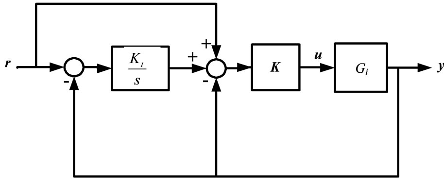
Figure 11. The integral-robust controller scheme.
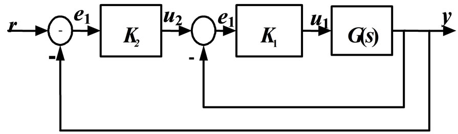
Figure 12. Block diagram of 2 DOF H∞ controller.
model Gs(s) and a proper stable weighting function Ws(s)
 (32)
(32)
The selection of Ws(s) poles can be set by γ < 1 and by having a nonminimum phase response [29].
It is clear that the requirement in this stage is to find a controller K1 that stabilizes the closed-loop transfer function F(s) with  and performing the required response, which is mainly related to a good selection of the weighting function.
2) Design the second H∞ controller on the stabilized system to get an improved robust performance. The robust configuration as described in Section 3.1 can be applied in this stage to design K2, using the same previously selected weighting functions; optimized We (28), Wu (27) and the intelligently identified Wa (26). The selected stable weighting function is
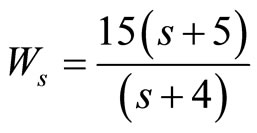 (33)
(33)
The corresponding H∞ synthesis results in γ = 0.9686 which is less than 1 indicating nominal stability, while the second H∞ controller is obtained with γ = 0.1424. However, the resulted robust controller is highly sensitive due to the large gain of the resulted controller and the presence of a pole in the origin. Attention is required in the practical application to avoid unexpected high starting oscillation; decreasing the resulted controller gain might be required in this case.
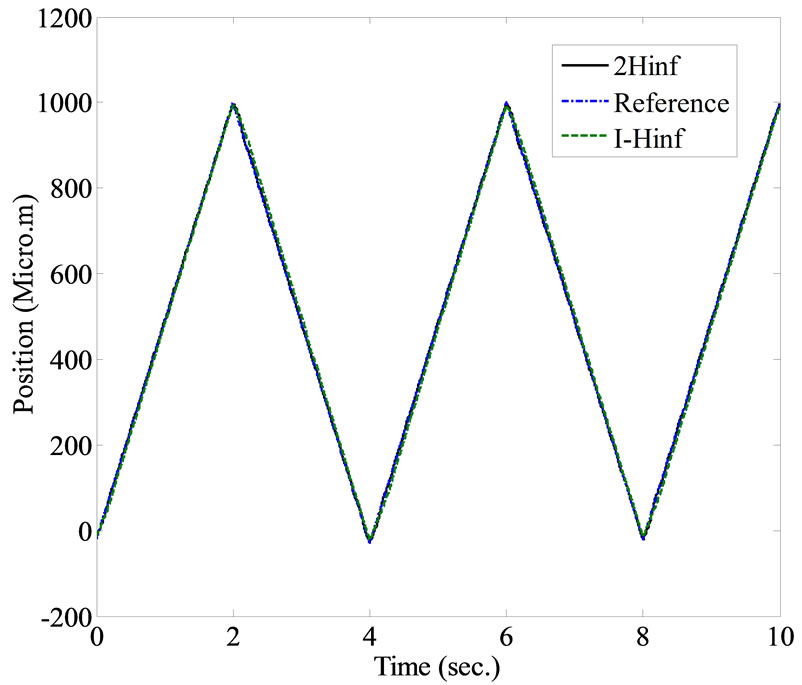
The same previously applied reference signals are used to demonstrate the tracking performance of both the integral-H∞ and the 2 DOF H∞ controller configurations. In the next set of experiments, the triangular reference signal is implemented, as shown in Figure 13. It can be noticed that the minimum tracking error can be achieved
 (a)
(a)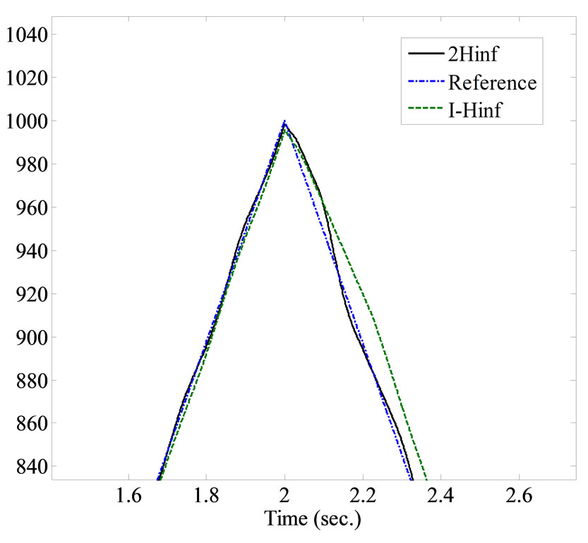 (b)
(b)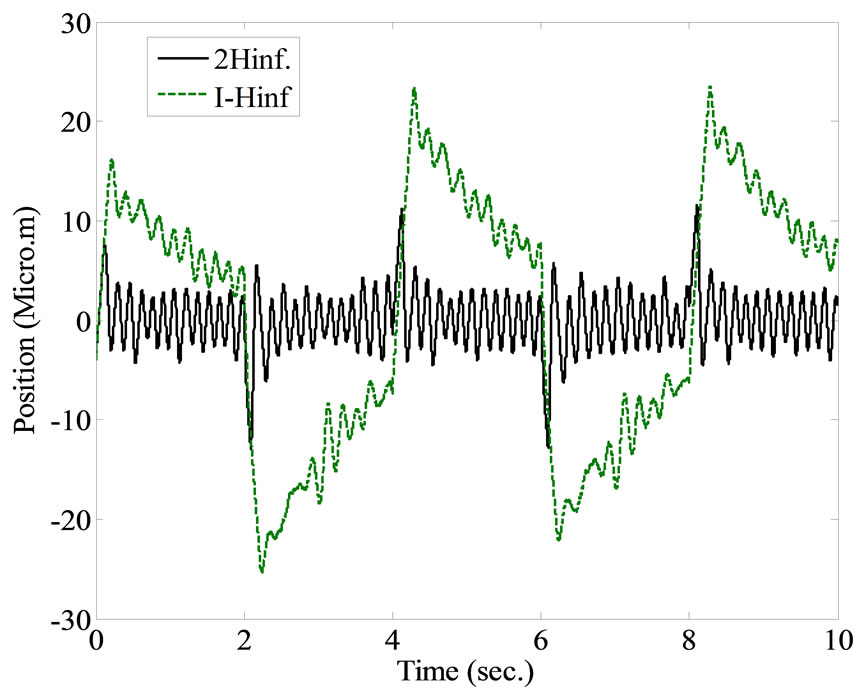 (c)
(c)
Figure 13. Experimental results using Integral-H∞ and 2 DOF H∞ robust controllers, applying a triangular reference input signal. (a) The transient response of the closedloop controlled system; (b) A magnified plot; (c) The tracking error.
with the 2-DOF H∞ controller configuration, where its maximum value will not exceed 10.7 μm, as shown in Figure 13(b). Each experiment was repeated 10 times. The average error, standard deviation and RMS value were calculated. Implementation of the 2 DOF H∞ controller scheme provides better tracking performance than the integral-H∞ controller scheme as clearly shown in Table 3.
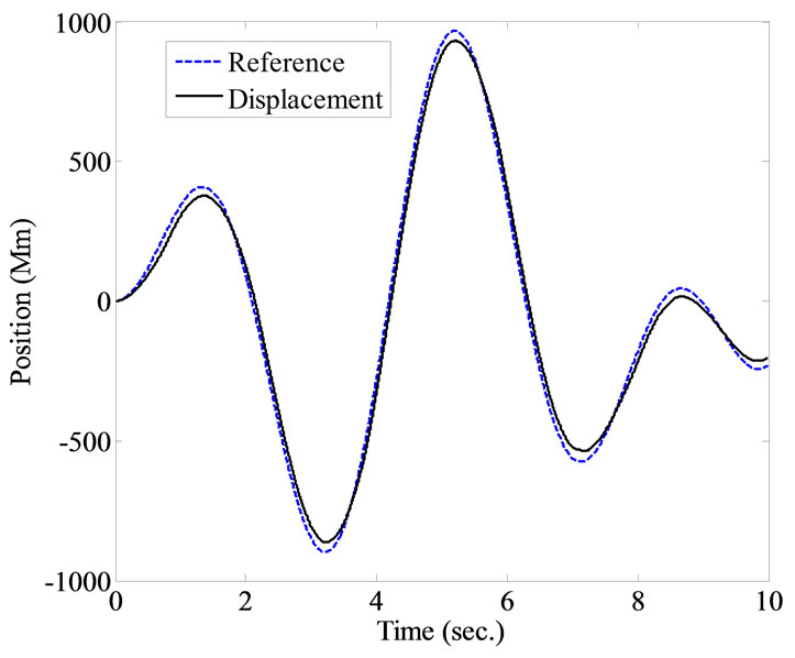
Figure 14 shows the resulted tracking performance using the specially designed sinusoidal reference signal. Except at the turning points, smooth tracking is achieved using either of the two robust configurations, however, the tracking error using the 2 DOF H∞ can be considerably significantly reduced as clearly shown in Table 4, where the numerical results of the average error, standard deviation and RMS value for 10 experiments are given.
Comparing the mean value of tracking errors from Table 2 with those from Table 3, and Table 4 indicates considerable improvements in tracking performance when applying the developed control schemes; For the results of triangular input signals, the mean value of tracking error is reduced by 1.5308 times when integral-H∞ is implemented and reduced by 2.7617 times when 2 DOF H∞ is applied. And for the results of using special sinusoidal input signal, the tracking error is improved by a factor of 2.2966 for the integral-H∞ set and 4.6313 for the 2 DOF H∞ set of results. Similarly, the STD values are considerably improved. That reflects the effectiveness of the applied approach for the system under study.
5. Conclusions
In this paper, robust controller design and analysis for a single axis servo positioning system is developed. Some comments and conclusions can be summarized as follow:
1) Intelligent unstructured estimated uncertainty is utilized to synthesize two H∞ robust controllers. v-gap is utilized to validate the uncertainty representation for better stability margin and compared with the developed µ analysis results for further investigation. Experimental results reflect the effectiveness of the applied practical methodology of quantifying the uncertainty of a positioning system with respect to the gained stability and performance.
2) Constrained optimized performance weighting function is formulated and utilized in the robust controller design in order to obtain accurate parameters in a considerably less time of search and calculation.
3) Integral H∞ and 2 DOF H∞ control schemes are developed. The 2 DOF H∞ scheme can achieve less track-
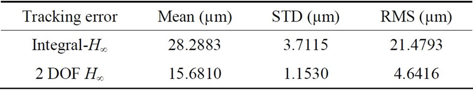
Table 3. Performance measures of integral-H∞ and 2 DOF H∞ control schemes using triangular input signal.

Table 4. Performance measures of integral-H∞ and 2 DOF H∞ control schemes using special sinusoidal input signal.
 (a)
(a)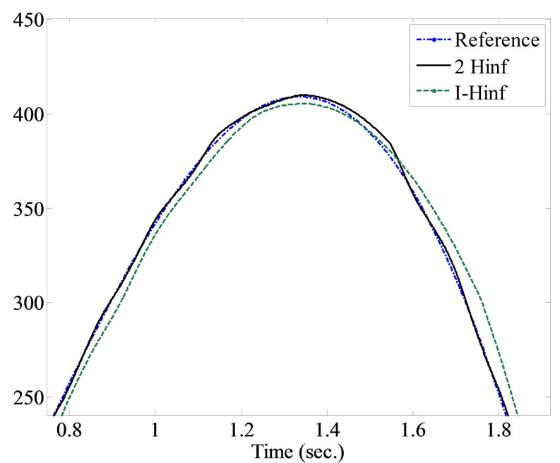 (b)
(b)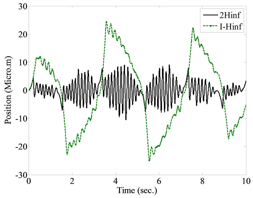 (c)
(c)
Figure 14. Experimental results using 2 DOF H∞ and integral-H∞ robust controllers, applying a specially designed reference input signal. (a) The transient response of the closed-loop controlled system; (b) Magnified plot; (c) The tracking error.
ing error, but the controlled system will be more sensitive and starting oscillations may be developed. The integral-H∞ scheme can achieves good tracking providing robust stability condition is satisfied. Experimental demonstrations validate the benefits of each of these robust control configurations. Improved resolution and tracking performance are obtained.
4) The requirement for only measuring the position sensor to develop the identification and control in a straightforward procedure indicates also a good cost performance.
5) Further studies on studies on nonlinear robust control of the system is currently under development. The motivation is to handle the effects of wider range of uncertainties and operating conditions efficiently.
REFERENCES
- S. Endo, H. Kobayashi, C. J. Kempf, S. Kobayashi, M. Tomizuka and Y. Hori, “Robust Digital Tracking Controller Design for High-Speed Positioning System,” Control Engineering Practice, Vol. 4, No. 4, 1996, pp. 527- 536. doi:10.1016/0967-0661(96)00036-6
- H.-S. Park, P. H. Chang and D. Y. Lee, “Concurrent Design of Continuous Zero Phase Error Tracking Controller and Sinusoidal Trajectory for Improved Tracking Control,” American Society of Mechanical Engineers, Journal of Dynamic Systems, Measurement, and Control, Vol. 123, 2001, pp. 127-129. doi:10.1115/1.1343464
- Z. Z. Liu, F. L. L. Luo and M. H. Rashid, “QFT-Based Robust and Precision Motion Control System for a High Speed Direct-Drive XY Table Positioning Mechanism,” Industry Application Conference, 2003, 38th IAS Annual Meeting, 12-16 October 2003, Vol. 1, pp. 293-300.
- L. Xu and B. Yao, “Output Feedback Adaptive Robust Precision Motion Control of Linear Motors,” Automatica, Vol. 37, No. 7, 2001, pp. 1029-1039. doi:10.1016/S0005-1098(01)00052-8
- Y. Honga and B. Yao, “A Globally Stable Saturated Desired Compensation Adaptive Robust Control for Linear Motor Systems with Comparative Experiments,” Automatica, Vol. 43, No. 10, 2007, pp. 1840-1848. doi:10.1016/j.automatica.2007.03.021
- W. F. Xie, “Sliding-Mode-Observer-Based Adaptive Control for Servo Actuator with Friction,” IEEE Transactions on Industrial Electronics, Vol. 54, No. 3, 2007, pp. 1517- 1527. doi:10.1109/TIE.2007.894718
- J. Dong, S. M. Salapaka and P. M. Ferreira, “Robust MIMO Control of a Parallel Kinematics Nano-Positioner for High Resolution High Bandwidth Tracking and Repetitive Tasks,” 46th IEEE Conference on Decision and Control, New Orleans, 12-14 December 2007, pp. 4495- 4500.
- K. B. Choi, S. H. Kim and B. W. Choi, “Moving-Magnet Type Precision Miniature Platform for Fine Positioning and Compliant Motion,” Mechatronics, Vol. 11, No. 7, 2001, pp. 921-937. doi:10.1016/S0957-4158(00)00055-6
- H. J. Shin and H. J. Pahk, “Development of the Precision Planer Motor Stage Using a New Magnet Array and Robust Control with Parametric Uncertainty Model,” The International Journal of Advanced Manufacturing Technology, Vol. 33, No. 7-8, 2007, pp. 643-651. doi:10.1007/s00170-006-0514-6
- Z. Z. Liu, F. L. Luo and M. A. Rahman, “Robust and Precision Motion Control System of Linear-Motor Direct Drive for High-Speed X-Y Table Positioning Mechanism,” IEEE Transactions on Industrial Electronics, Vol. 52, No. 5, 2005, pp. 1357-1363. doi:10.1109/TIE.2005.855661
- E. Rijanto, “Quasi Mixed
 Controller for High Precision Positioning Device,” IEEE Proceedings of the 6th International Workshop on Advanced Motion Control, Nagoya, 30 March-1 April, 2000, pp. 335-338.
 - A. Sebastian and S. M. Salapaka, “Design Methodologies for Robust Nano-Positioning,” IEEE Transactions on Control Systems Technology, Vol. 13, No. 6, 2005, pp. 868- 876. doi:10.1109/TCST.2005.854336
- C. Lee and S. M. Salapaka, “Fast Robust Nanopositioning—A Linear-Matrix Inequalities-Based Optimal Control Approach,” IEEE/ASME Transactions on Mechatronics, Vol. 14, No. 4, 2009, pp. 414-422.
- H. Choi, G. D. Buckner and N. S. Gibson, “Neural Robust Control of High-Speed Flexible Rotor Supported on Active Magnetic Bearings,” American Control Conference, Minneapolis, 14-16 June 2006.
- G. R. Yu and C. W. Tao, “Intelligent H∞ Control of Nano-Positioning Systems,” IEEE International Conference on Systems, Man, and Cybernetics, Taipei, 8-11 October 2006, pp. 1729-1733.
- S. M. Raafat, R. Akmeliawati and W. Martono, “Intelligent Robust Control Design of a Precise Positioning System,” International Journal of Control, Automation and Systems, Vol. 8, No. 5, 2010, pp. 1123-1132.
- R. Akmeliawati, S. M. Raafat and W. Martono, “Improved Intelligent Identification of Uncertainty Bounds; Design, Model Validation and Stability Analysis,” International Journal of Modeling, Identification, and Control, Vol. 15, No. 3, 2012, pp. 173-184. doi:10.1504/IJMIC.2012.045690
- H.-P. Lee and D. K. Shmidt, “Robust Two-Degree of Freedom H∞ Control of a Seeker Scan Loop System,” IEEE Proceedings Control Theory and Applications, Vol. 149, No. 2, 2002, p. 149. doi:10.1049/ip-cta:20020097
- M. H. Smith, A. M. Annaswamy and H. Slocum, “Adaptive Control Strategies for a Precision Machine Tool Axis,” Precision Engineering, Vol. 17, No. 3, 1995, pp. 192-206. doi:10.1016/0141-6359(94)00019-V
- S. Skogestad and I. Postlethwait, “Multivariable Feedback Control: Analysis and Design,” John Wiley and Sons, Hoboken, 1997.
- K. Zhou and J. C. Doyle, “Essentials of Robust Control,” Prentice-Hall, Inc., Upper Saddle River, 1998.
- W. Reinelt, A. Garulli and L. Ljung, “Comparing Different Approaches to Model Error Modelling in Robust Identification,” Automatica, Vol. 38, No. 5, 2002, pp. 787- 803. doi:10.1016/S0005-1098(01)00269-2
- J. S. R. Jang, “ANFIS: Adaptive-Network-Based Fuzzy Inference System,” IEEE Transactions on Systems, Man and Cybernetics, Vol. 23, No. 3, 1993, pp. 665-685. doi:10.1109/21.256541
- G. Vinnicombe, “Uncertainty and Feedback: H∞ LoopShaping and the v-Gap Metric,” University of Cambridge, England, 2000.
- G. Balas, R. Chiang, A. Packard and Safonov, “Robust Control ToolboxTM 3 User’s Guide,” The MathWorks Inc., Natick, 2008.
- S. M. Raafat and R. Akmeliawati, “Bounded Constrained Optimization of Performance Weighting Function for Precise Robust Positioning Control System,” International Conference on Mechatronics, Kuala Lump, 17-19 May 2011, pp. 1-7.
- G. F. Franklin, J. D. Powelland and A. Emami-Naeini, “Feedback Control of Dynamic Systems,” Prentice Hall, Inc., Upper Saddle River, 2002.
- D.-W. Gu, P. H. Petkov and M. M. Konstantinov, “Robust Control Design with MATLAB,” Springer-Verlage, London, 2005.
- M. Arzifian, “Design an H∞ Controller for Force Control in Magnetic Levitation Systems,” Master’s Thesis, University of Technology, Baghdad, 2006.