Circuits and Systems
Vol. 3 No. 3 (2012) , Article ID: 20194 , 11 pages DOI:10.4236/cs.2012.33035
Appropriate Placement of Fault Current Limiting Reactors in Different HV Substation Arrangements
Faculty of Electrical and Computer Engineering, University of Tabriz, Tabriz, Iran
Email: hseyedi@tabrizu.ac.ir
Received June 11, 2011; revised May 7, 2012; accepted May 14, 2012
Keywords: Current Limiting Reactor; Fault Current Limiter; Bus Arrangement
ABSTRACT
Short circuit currents of power systems are growing with an increasing rate, due to the fast development of generation and transmission systems. Current Limiting Reactor is one of the effective short circuit current limiting devices. This technique is known to be more practical than other available approaches. In this paper, proper application of CLR to HV substations is proposed, based on a comprehensive short circuit analysis of 4 well-known substation bus bar arrangements. Eventually, appropriate place and number of CLRs is recommended for each bus bar arrangement.
1. Introduction
In modern power system, the increasing rate of energy demand imposes development of generation and transmission systems. As an unwelcome consequence of generation and transmission systems development, short circuit current are day-to-day increasing. Many utilities, all over the world, are experiencing the problem of astonishing short circuit levels. For instance, some utilities in Brazil, China, Iran and Kuwait may be mentioned [1- 4]. Increasing rate of short circuit level causes undesired consequences which may be summarized as follows:
• Equipments are exposed to unacceptable thermal stresses;
• Equipments are exposed to unacceptable electro-dynamic forces;
• Short circuit breaking capability of high voltage circuit breakers is typically limited to 80 KA [5];
• In order to prevent equipment damage, faster circuit breakers are required. This requirement faces both technological and economical restrictions;
• Step and touch voltages are also increased as a result of increasing short circuit levels. This will cause safety problems to the personnel;
• Switching over voltage transients will become more severe, due to significant short circuit current.
Due to the above-mentioned problems, the subject of short circuit level reduction has gained a considerable attention in recent years among electric utilities. Numerous short circuit current limitation techniques have been introduced in the literature. One could mention the following important approaches:
• Current Limiting Reactor [1,2,6,7];
• Solid State Fault Current Limiters [8,9];
• Superconducting Fault Current Limiters [10-15];
• Fuse [16];
• Is limiter [17];
• Power system reconfiguration;
• Bus bar splitting techniques in the substations;
• Disconnection of some lines from the critical substations;
• Application of high impedance transformers;
• HVDC links [18];
• Design of higher voltage transmission networks [4];
• Application of neutral reactor.
The above mentioned approaches are briefly described in Section 2. Among these methods, Current Limiting Reactor may be the most practical approach. Methods such as SFCL are more or less passing their initial research stage. In addition they are still uneconomical. Other methods are either unacceptable due to their shortcomings or can not be economically justified.
In this paper, appropriate placement of CLR within the substation, considering four common busbar arrangements, is proposed. The main objective of this work is to find proper place for CLRs, which satisfy the following conditions:
• The short circuit level is reduced as much as possible;
• Minimum number of CLRs is applied.
The appropriate places are determined, based on comprehensive simulation studies followed by a complete analysis of the results. Using the results of this work, electric utilities could easily find the proper place of CLRs whenever required.
In Section 2 of this paper, important short circuit limitation techniques are briefly described. In the third Section, characteristics of CLR are explained in detail. In Section 4, numerous possible places for the installation of CLRs are introduced. In Section 5, comprehensive simulation studies of this work are presented. Finally, in Section 6 results of simulations are discussed. Based on the discussion of Section 6, appropriate CLR places are recommended for each busbar arrangement.
2. Short Circuit Current Limitation Techniques
In this section, the previously-introduced short circuit reduction methods are briefly described.
2.1. Current Limiting Reactors
CLR is a will-known fault current limiting technique. Compared with many other methods, it is more economical. In addition its effect on the reliability of substation is negligible. However, it occupies a relatively large area in the substation, due to safety considerations. Moreover, it may degrade both voltage stability and transient stability of the system. More detail about CLR will be presented in Section 3 [1,2,6,7].
2.2. Solid State Fault Current Limiters
SSFCLs apply power electronic switches. These limiters are, practically, restricted to the distribution level. Moreover, they are complicated and expensive. Some types of SSFCLs apply series resonance or parallel resonance circuits [8,9].
2.3. Superconducting Fault Current Limiters
Superconducting material such as YBCO, NbTi and MgB2 transit from superconducting state to the normal state, if exposed to high current levels. Due to this feature of superconductors, they can be applied as a fault current limiter. During normal operation of power system, SFCL resistance is negligible. However, as soon as the fault current shows up, SFCL quenches and consequently its resistance increases considerably. Resistive, inductive and transformer type SFCLs are important types of this device [10-15]. Although this limiter seems to be an ideal fault current limiter, it is still too expensive, especially due to the cost of its complicated cryogenic system.
2.4. Fuse
Fuse is a fast short circuit interrupting device. Therefore, it might be considered as a limiter. It is simple and costeffective. However, it is technically restricted to below 40 kV nominal voltages and 200 A nominal currents. In addition to these restrictions, fuse must be replaced, following every interruption. Therefore, it may not be used when high speed auto-reclosing is required.
2.5. Is Limiter
Is Limiter is the improved version of fuse. In this device, during normal operation, major portion of current passes through a path parallel with the fuse. When the short circuit occurs, the parallel path is opened, using electrodynamic forces of fault current. Consequently, the fault current is commutated to the fuse. This way, the problem associated with the limited nominal current of fuse is resolved. Is Limiter is claimed to be capable of interrupting fault currents up to 5 kA, within 1 ms after occurrence of the fault. However, it is still limited to 40 kV rated voltage [17].
2.6. Power System Reconfiguration
This approach is, to some extent, empirical. There is no definite rule for this method. In other words, it is casedependent. It also depends on parameters such as creativity and familiarity of the engineer with the system under study. In many cases, it may result in considerable reduction of fault current level. Moreover, it may improve transient stability and voltage stability of the system.
2.7. Bus Bar Splitting Techniques in the Substations
In this approach, in order to reduce fault current level, bus section or/and bus coupler circuit breakers are opened. Power system operators are seriously opposed to this approach. Their disagreement is mainly due to the fact that bus bar splitting significantly decreases reliability of the substation. Moreover, it affects integrity of the system, which may result in lower transient stability and voltage stability margins. However, from the short circuit reduction point of view, this method is more effective than CLR. This is due the fact that bus bar splitting is equivalent to application of a CLR with infinite reactance. Meanwhile, this method may be considered as a temporary strategy which is acceptable only in emergency situations.
2.8. Disconnection of Some Lines from the Critical Substation
In this technique, in order to reduce bus bar short circuit level, 2 transmission lines are disconnected from the bus bar. Afterwards, these lines are reconnected together, outside the substation. Similar to the bus bar splitting method, this technique is not acceptable, from the power system operation point of view. Undesired effects on the reliability, transient stability and voltage stability of power system are known to be the main disadvantages of this approach.
2.9. Application of High Impedance Transformers
Using high impedance transformers may result in the considerable reduction of fault current level. However the undesired effects on transient stability and voltage stability might be significant.
2.10. HVDC
Replacement of tie lines with HVDC links will diminish inter-area short circuit currents. This will, obviously, restrict fault current levels. However, in most cases, this method is not economically justified.
2.11. Design of Higher Voltage Transmission Networks
In this method, the existing power system is split to several islands. Afterwards, a higher voltage system is designed and then the islands are reconnected through the higher voltage network [4]. This method seems not to be practical, as it is both complicated and costly.
2.12. Application of Neutral Reactor
Application of reactors in the neutral of transformers, will limit the earth fault current level. As the majority of faults include ground, this method may be considered as an effective approach [4].
Among the above mentioned approaches, CLR may be the most practical method. Since it does not affect reliability of the system, power system operators may accept it. However, as it might degrade voltage stability and transient stability margins of the system, its application requires careful attention.
3. Introduction to CLR
In this section important characteristics of CLR are introduced in detail.
3.1. Type of CLR
Dry type CLR and oil type CLR are the two well-known types of CLR. Dry type is an air-core reactor with copper or aluminum windings. Generally, iron cores are not used in CLRs, due to the possibility of saturation. Since this device is installed in series with the main circuit, possibility of iron core saturation, specially, during short circuit conditions, is high. Therefore, dry type air-core reactor is the common type of CLR, used in power systems. One of the main problems, associated with this device, is the safety problem due to the magnetic flux distributed through the space around CLR. Therefore, air-core CLRs require proper fencing due to the personnel safety considerations.
Characteristics of oil type reactors are mainly similar to the dry type. However, the oil type is specifically designed for the heavily polluted environments. Moreover, oil type CLR has got the following advantages:
- Dielectric constant of oil is greater than air. This will result in the smaller size of oil type CLR, compared with the dry type.
- Heat transfer capability of oil is higher the air. This will result in some advantages and savings during the design stage.
3.2. Technical Specifications
Important technical parameters of CLRs may be listed as follows:
- Nominal voltage;
- Nominal frequency;
- Short circuit capacity of the system;
- Basic insulation level;
- Continuous operating current;
- Rated inductance;
- Type (dry or oil);
- Class (indoor or outdoor).
3.3. Practical Considerations
CLRs may significantly reduce short circuit level. However, some practical restrictions must be considered, before installing CLRs.
- Voltage drop: CLRs may affect voltage profile of the system. Hence, when CLR is recommended for a system, voltage stability studies of the system should be repeated.
- Transient stability: in addition to voltage stability, CLR may also degrade transient stability of the system.
- Energy consumption: since the main current of power system is continuously passing through the CLR, energy consumption of the device might be significant. This issue must be considered in the CLR design stage.
- Distributed magnetic flux: required safety clearances around the CLR should be double-checked, in order to consider the high magnetic flux, distributed through the space. This will necessitate careful fencing.
- Transient recovery voltage: when the circuit breakers interrupt short circuit or even normal load current, a transient voltage appears across the opened contacts. This voltage is known as Transient Recovery Voltage. TRV and its rate of rise, known as Rate of Rise of Recovery Voltage are considered as important parameters for the circuit breaker manufacturers. If either TRV or RRRV exceeds the circuit breaker capability, possibility of secondary arc will be increased. This will impose a significant stress on the circuit breaker and other equipments.
According to the analyses of [1] and [2], CLR affects both TRV and RRRV in the following manner:
• It reduces the peak of TRV. This is an advantage of CLR.
• It increases RRRV. This is a disadvantage of CLR. Unfortunately, RRRV is more critical than TRV. Therefore, prior to the installation of CLR, accurate transient studies are required.
3.4. Selection of CLR Inductance
Appropriate value of CLR inductance is dependent on the system, under study. In Figure 1, maximum short circuit current of a simulated system is depicted as a function of CLR reactance, ωL. The simulated system will be introduced in Section 5.
According to Figure 1, as L increases, slope of the Isc- L curve decreases. Therefore, for the values of ωL greater than 50 Ω, variations of L will not significantly change Isc. Therefore, in this simulation 50 Ω is a limit, which is called “efficiency limit” in [2]. From the short circuit reduction point of view, 50 Ω is an effective value for ωL. However, in practice since transient stability, voltage stability and also TRV restrictions should also be taken into consideration, ωL is not necessarily selected to be 50 Ω.
4. Candidate Places for CLR in the Substations
At least 4 locations in the substation may be the candidate places for installation of CLR. These candidates are introduced as follows.
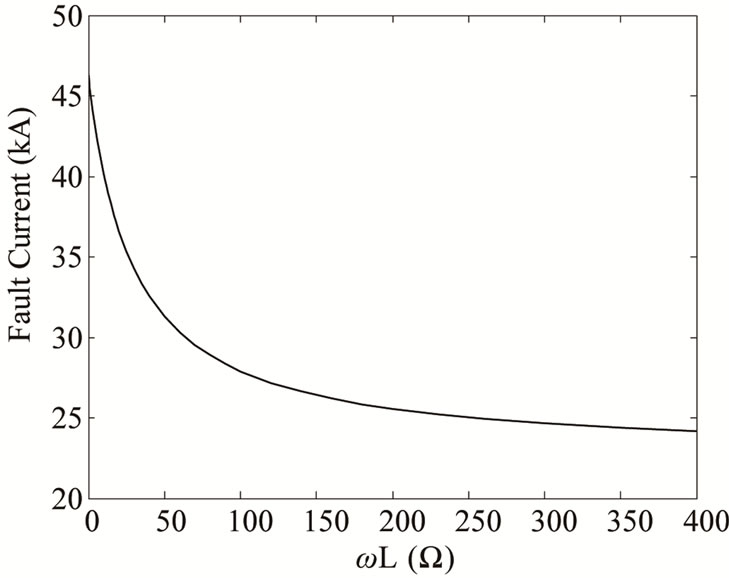
Figure 1. Effect of inductance on fault current level.
4.1. In Series with the Bus Section Breaker
In both single bus bar and double bus bar arrangements, the main bus is divided into 2 sections. These sections are connected by either circuit breaker or disconnecting switches. Figure 2 depicts the double-bus bar arrangement. In this figure, breakers number 1 and number 2 are the bus section and bus coupler breakers, respectively.
Installation of CLR in series with the bus section breaker is a suitable option. This configuration is shown in Figure 3. Since in this configuration, CLR is not connected directly in series with any feeder, effects on the transient stability and voltage stability seem to be tolerable.
4.2. In Series with the Bus Coupler
This configuration is shown in Figure 4. In this case, CLR is installed in series with breaker number 2, the bus coupler breaker. Again, it is expected that degradation of voltage stability and transient stability margins will not be significant.
4.3. In Series with the Critical Feeders
Each feeder, connected to the bus bar, contributes to the
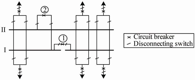
Figure 2. Double bus bar arrangement.
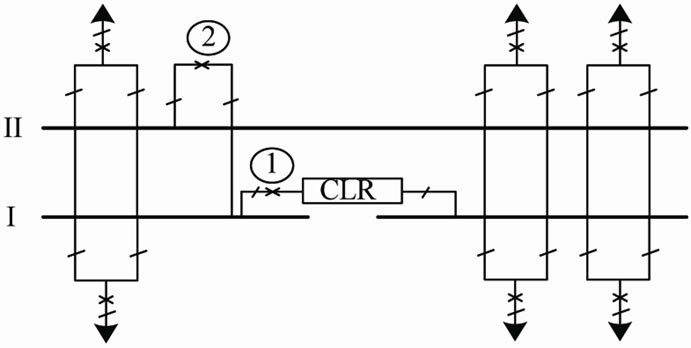
Figure 3. CLR in series with the bus section breaker.
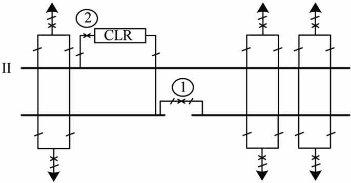
Figure 4. CLR in series with the bus coupler breaker.
short circuit level. However, contribution of some feeders is greater than others. Once the contribution of each feeder to the short circuit level has been evaluated, it is possible to recognize the critical feeders. Critical feeders are those which supply a great portion of short circuit current. Obviously, if CLRs are installed in series with the critical feeders, fault current level will significantly be decreased. This configuration is shown in Figure 5.
Since in this configuration, CLR is installed directly in series with feeder, significant decrease in transient stability and voltage stability margins is expected.
4.4. CLR, Connecting Adjacent Bus Bars or Substations
In some cases, there are adjacent bus bars or substations. In general, utilities tend to connect these adjacent sections to each other, due to its positive impact on the reliability, voltage stability and transient stability of the system. However, in many cases, high short circuit levels prevent this connection. In this situation, it is possible to connect the separated sections by CLRs. For instance, in Brazil, two 550 kV adjacent substations have been connected by a CLR [1]. In reference [4], connection of adjacent 1.5 breaker bus bars by CLRs, have been proposed. This configuration is depicted in Figure 6.
5. Appropriate CLR Placement in Different Arrangements
In this section a comprehensive short circuit study is
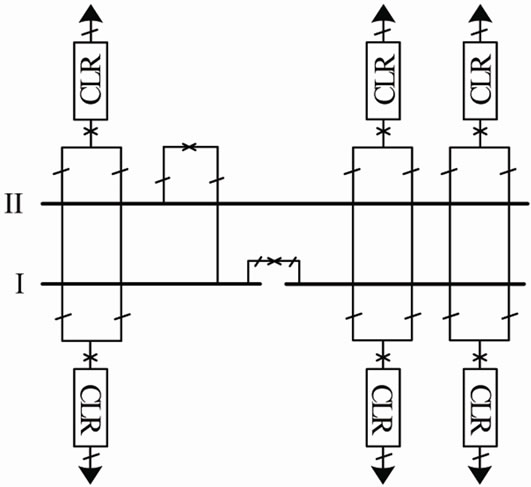
Figure 5. CLR in series with critical feeders.
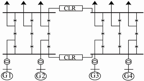
Figure 6. Connection of 1.5 breaker bus bars by CLRs.
performed. Four well-known bus bar arrangements are modeled in the Electro Magnetic Transients Program (EMTP). Six transmission lines with lengths of 60, 240, 170, 130, 250 and 75 km are connected to the simulated substation. For each bus bar arrangement, at the first stage, without any CLR, short circuit levels associated with different fault locations are obtained. Afterwards, CLRs are placed in different locations and the short circuit levels are again evaluated. Impedance of CLR is assumed to be 20 Ω in all simulation studies. Based on the simulation results followed by a complete discussion, the most appropriate locations of CLRs are introduced. The optimal placement is based on the impact of CLR on the short circuit level. However, the impacts on transient stability and voltage stability are also discussed. It is worth mentioning that, in order to save space, only a selected set of simulation results are presented in this section. However, all simulated cases have been considered in the discussion making conclusions.
5.1. Single Bus Bar with Bus Section Breaker
Configuration of this case study is shown in Figure 7.
In Table 1, results of the simulation study for fault occurring on Section A are listed. The results are related to different locations and different numbers of CLRs. In each case, both bus section current and total fault current are presented. At the next stage of simulation studies, assuming that fault occurs on Section B, case studies of Table 1 are repeated. The results are presented in Table 2. The next stage, short circuit studies are performed for fault occurring at the beginning of line 6. The results are presented in Table 3.
According to the results of Tables 1-3, bus section is the most appropriate place for CLR installation. In some cases, impact of bus section CLR on fault current level is even greater than application of 6 CLRs, 1 in series with each line.
5.2. Double Bus Bar Arrangement
Configuration of the simulated substation for this section is depicted in Figure 8. In this configuration, lines number 1, 2 and 4 are connected to bus number 1, while lines number 3, 5 and 6 are connected to bus number 2. This is a typical operating condition. The results of short circuit studies for faults occurring on bus 1, bus 2, at the beginning of line 1 and at the beginning of line 3 are presented
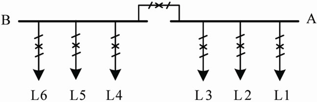
Figure 7. Single bus bar with bus section breaker.
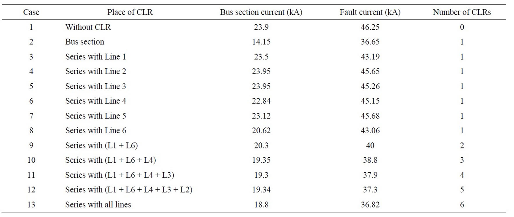
Table 1. Bus bar arrangement, fault on Section A.
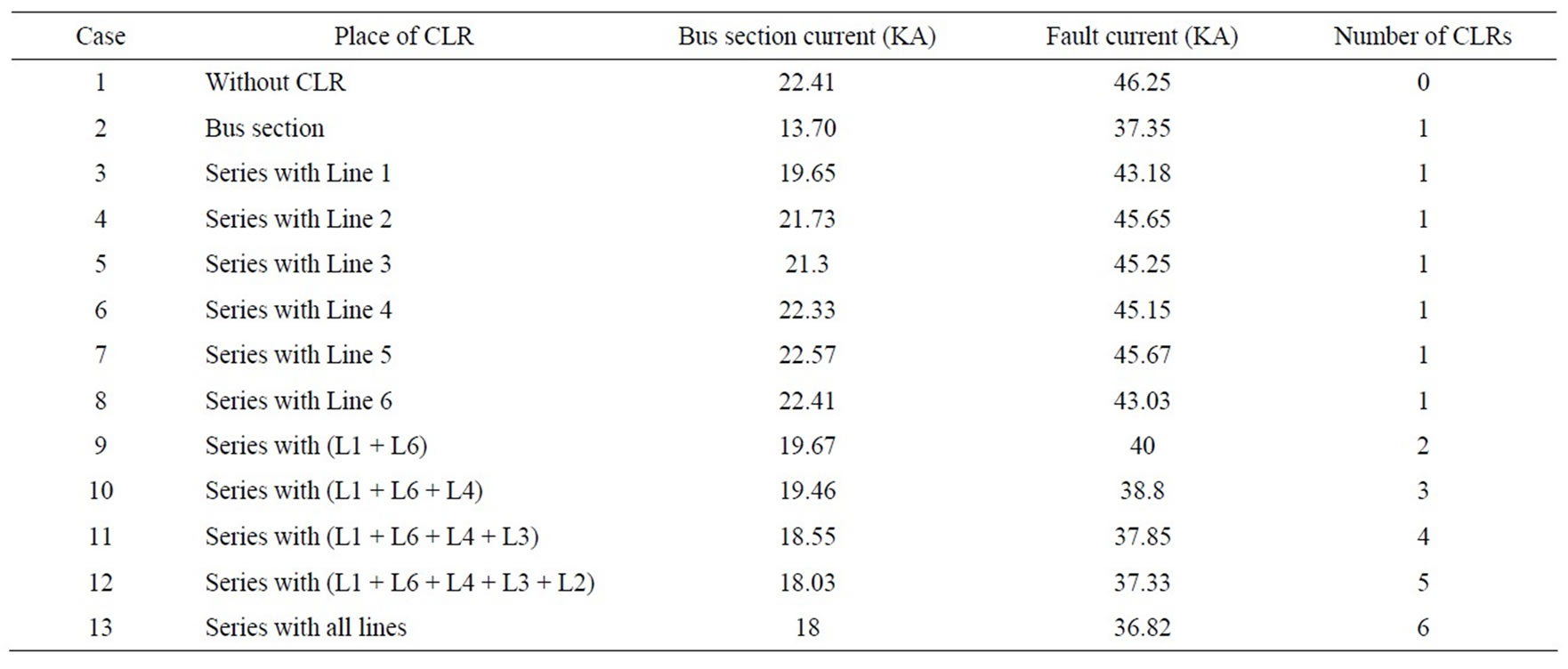
Table 2. Single bus bar arrangement, fault on Section B.
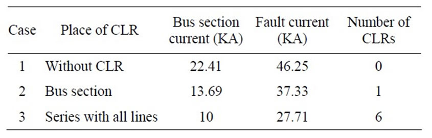
Table 3. Single bus bar arrangement, fault at the beginning of line 6.
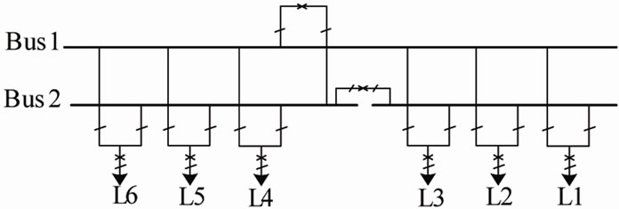
Figure 8. Double bus bar arrangement.
in Tables 4-7, respectively. Based on the results of Tables 4-7, installation of CLR in either bus coupler or bus section alone is not sufficient to limit fault current level
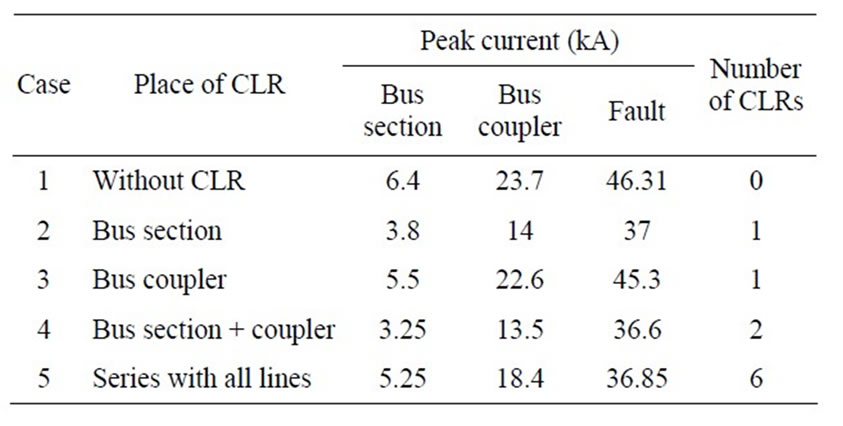
Table 4. Double bus bar arrangement, fault occurring at bus 1.
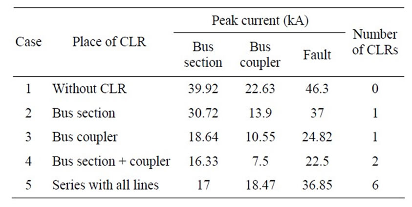
Table 5. Double bus bar arrangement, fault occurring at bus 2.
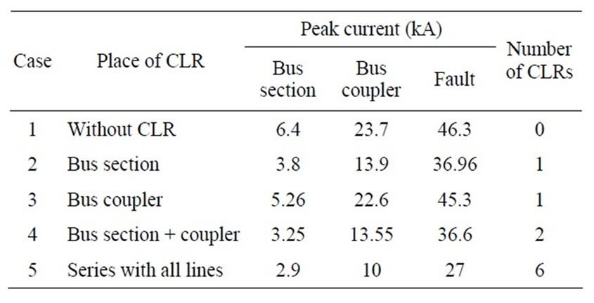
Table 6. Double busbar arrangement, fault occurring at the beginning of line 1.
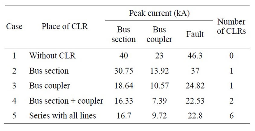
Table 7. Double bus bar arrangement, fault occurring at the beginning of line 3.
for all fault locations. Therefore, in the double bus bar arrangement, it seems that simultaneous installation of CLR in series with both bus section and bus coupler breakers is necessary.
To illustrate the effect of CLR on the fault current level, waveforms of the fault current, with and without CLR, are depicted in Figure 9. The dotted curve is related to the case without CLR. While, in the normal curve, CLRs are placed in series with both bus section and bus coupler breakers.
5.3. Double Breaker Arrangement
The double breaker arrangement is shown in Figure 10. In this configuration, each feeder is connected to both bus bars, through 2 sets of circuit breakers. Hence, the results of faults on bus bars 1 and 2 are identical. The results of fault analysis for faults on bus bar 1 and at the beginning of line 1 are presented in Tables 8 and 9, respectively.
In the double breaker arrangement, there is no bus coupler breaker. However, there might be a bus section breaker. Since all lines are connected to both bus bars at the same time, the bus section is always shorted through several parallel paths. Therefore, even if a bus section exists, it is not possible to apply CLR to this place. Hence, the bus section has not been considered in this
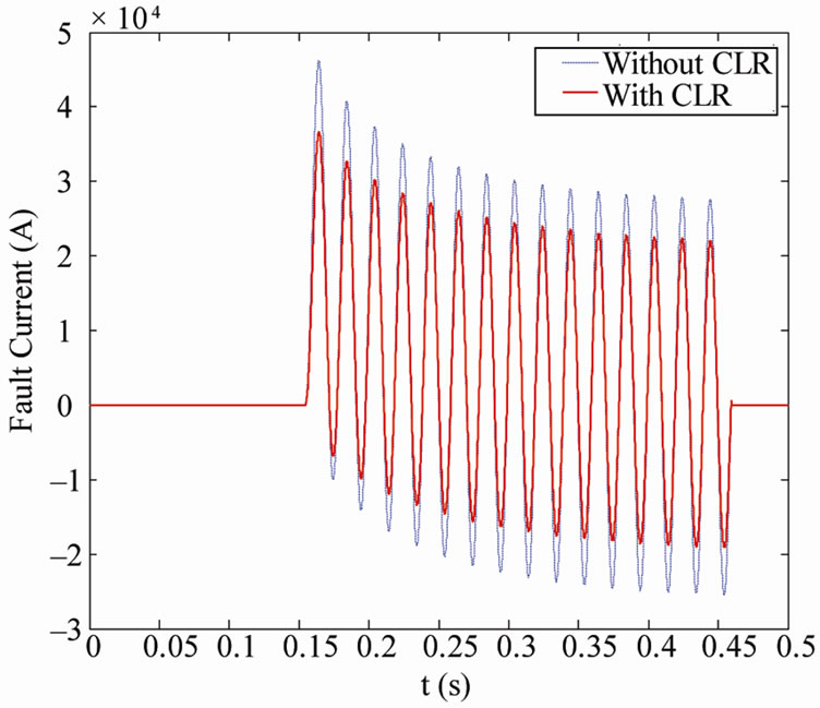
Figure 9. Impact of CLR on fault current, double bus bar arrangement.
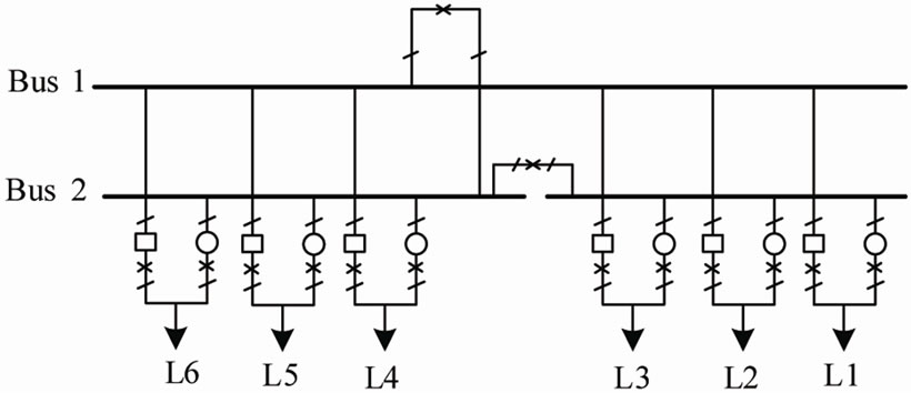
Figure 10. Double breaker arrangement.
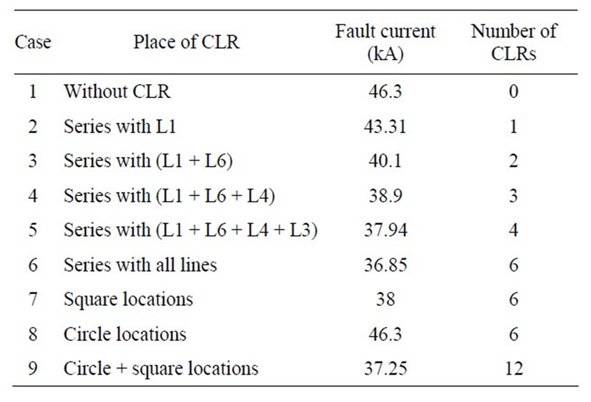
Table 8. Double breaker arrangement, fault at bus 1.
case. Instead, the circle and square positions are considered, as depicted in Figure 10. Based on the results of Tables 8 and 9, installation of CLR in either circle or square locations alone is not sufficient. On the other hand, installation of CLRs on both circle and square positions will require a large number of reactors, i.e. twice the number of lines. Therefore, these options are not acceptable. Instead, it recommended to install reactors in series with 1 or 2 critical lines, for example lines 1 and 6 in this study.
5.4. Breaker and a Half (1.5 Breaker) Arrangement
1.5-breaker arrangement is depicted in Figure 11. The results of simulation studies for faults at bus bar 1, the beginning of line 1 and bus bar 2 are listed in Tables 10- 12, respectively.
In the 1.5 breaker arrangement, if CLRs are to be installed between 2 bus bars, there must be at least 1 CLR in each bay. Even if one bay is without CLR, it will bypass all CLRs of other bays. For example if CLRs are installed in series with just B1 and B4 breakers, both of these CLRs will be bypassed through the B7-B8-B9 path. Therefore, for the three-bay arrangement shown in Figure 11, at least 3 CLRs are required. Based on the results of Tables 10-12, if CLRs are installed adjacent to one of the bus bars, for some fault locations CLRs will have no impact on the fault current. On the other hand, installa-
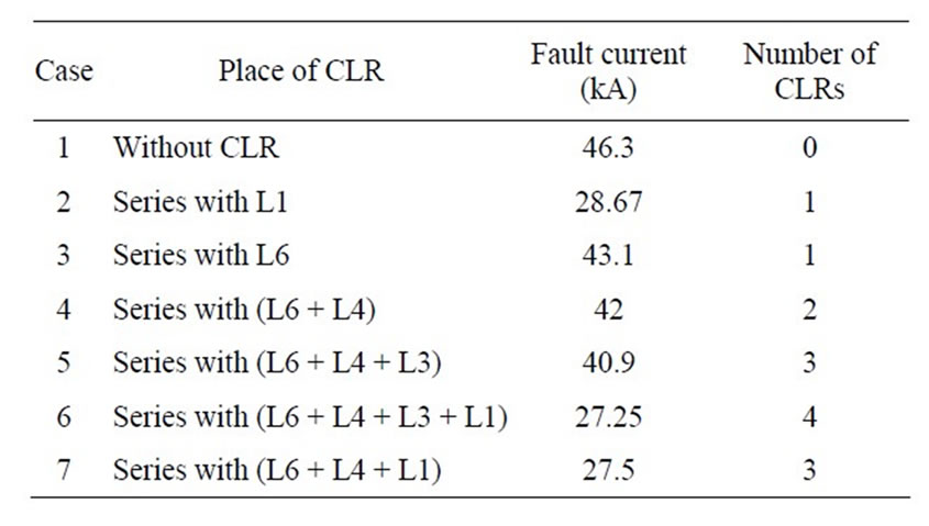
Table 9. Double breaker arrangement, fault at the beginning of line 1.
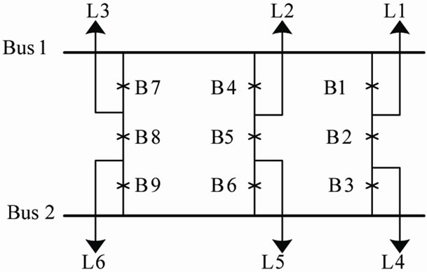
Figure 11. Breaker and a half arrangement.
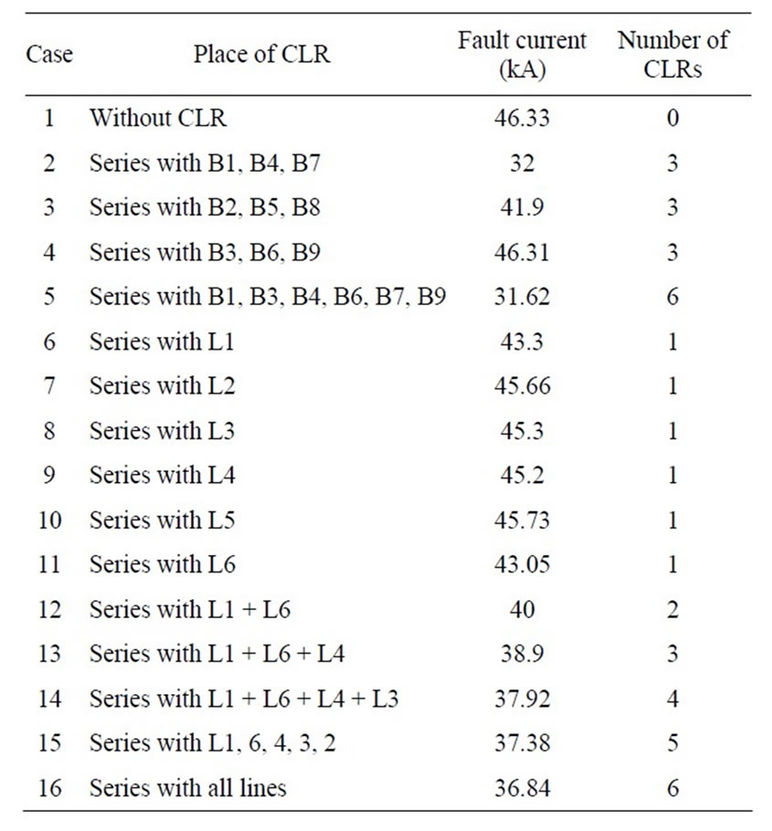
Table 10. 1.5 breaker arrangement, fault at bus 1.
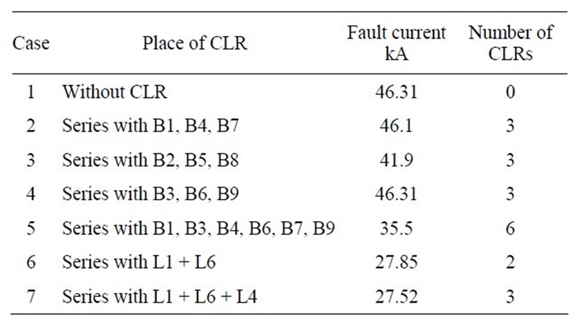
Table 11. 1.5 breaker arrangement, fault at the beginning of line 1.
tion of CLRs in series with the intermediate breakers, i.e. B2, B5 and B8, will reduce fault current for any fault location. However, the degree of reduction is not significant.
Figure 12 depicts the impact of CLR on the fault current level. Fault occurs on bus 1. In the dotted curve, no CLR is applied, while in the normal curve, three CLRs are connected in series with lines 1, 4 and 6.
6. Discussion
6.1. Single Bus Bar with Bus Section
According to the results of Tables 1 to 3, the following conclusions are made:
• Bus section is the most appropriate location for the installation of CLR. This is due to the fact that the bus section CLR restricts the current of 3 out of 6 feeders,
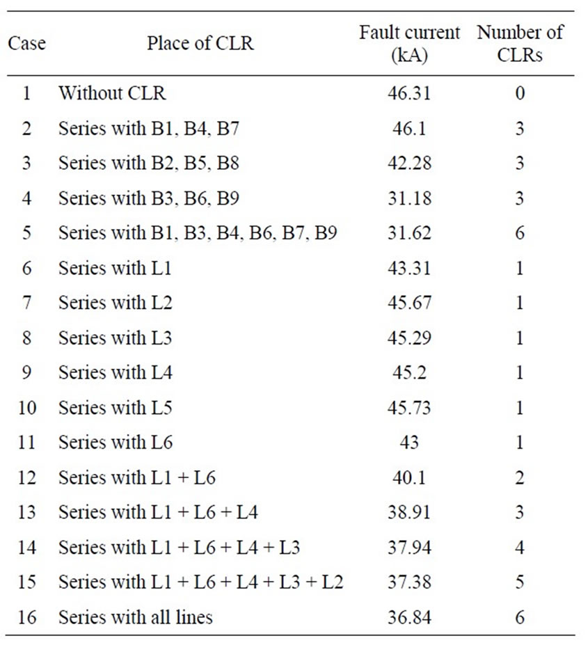
Table 12. 1.5 breaker arrangement, fault at bus 2.
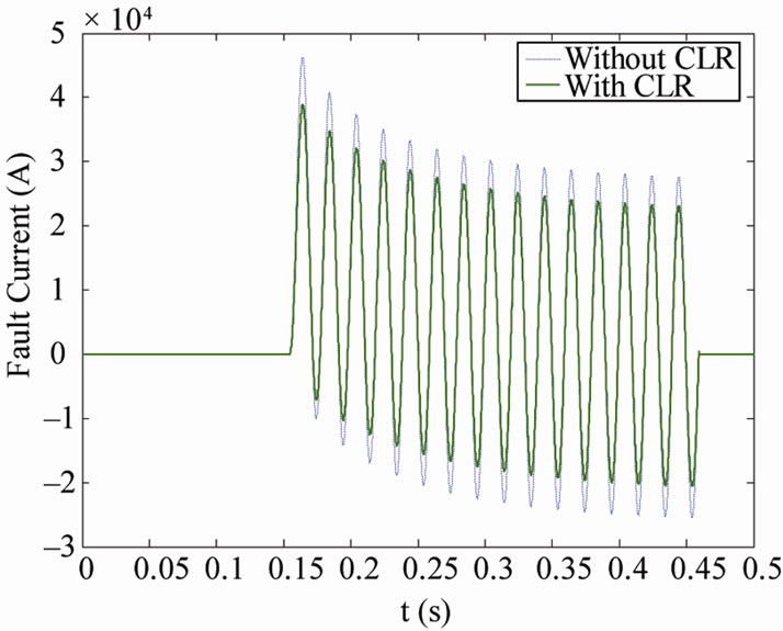
Figure 12. Impact of CLR on the fault current level, 1.5 breaker arrangement.
independent of the fault location. Therefore, installation of CLR in the bus section will be equivalent to the application of 3 CLRs in series with 3 out of 6 feeders.
• It is clear that the shorter the length of the line, the more it contributes to the fault current. Hence, lines number 1, 6 and 4 are the most critical lines respectively. Installation of CLRs in series with these lines is the most effective option, if the CLRs are to be installed in series with the lines. Although 3 CLRs are applied in this case, this option is still less effective, both technically and economically than placing 1 CLR in the bus section.
• In many cases application of 6 CLRs, i.e. in series with all feeders, is not much more effective than one CLR in the bus section.
• From the transient stability and voltage stability point of view, application of CLR in the bus section is more acceptable than in series with lines.
• According to the above discussion, installation of CLR in series with the bus section is recommended for the single bus bar arrangement.
6.2. Double Bus Bar Arrangement
Based on the results of Tables 4 to 7, the following points are made:
• Effectiveness of CLR application in the bus section is depended on the fault location. Depending on the fault location, this option may either be much effective or not effective at all. This is due to the fact that in some fault locations, the bus section CLR will not be on the current path of the majority of feeders.
• Similar to the bus section, installation of CLR in series with the bus coupler, will not guarantee that the short circuit current will be restricted for every fault location. Effectiveness of this option is also depended on the fault location.
• Application of two sets of CLR, one in the bus coupler and the other in the bus section, is the most effective option. In some cases their impact on the short circuit level, is approximately identical to application of 6 CLRs, one set in each feeder.
• In some specific cases application of 6 CLRs, i.e. in series with all feeders, is much effective than other options. However, this option is not practically acceptable. Since it significantly decreases transient stability and voltage stability margins.
• Based on the above notes, simultaneous application of CLRs in both bus section and bus coupler is recommended for double bus bar arrangement.
6.3. Double Breaker Arrangement
The following points are based on the results of Tables 8 and 9:
• In the double breaker arrangement, 3 option are available for CLR placement:
1) To install adjacent to 1 bus bar, i.e. circle or square locations of Figure 10.
2) To install adjacent to both bus bars, i.e. both circle and square locations of Figure 10.
3) To install in series with the feeders.
• If the CLR is to be installed adjacent to the bus bars, say bus bar 1, it should be applied to all locations between bus bar 1 and feeders connected to this bus bar. In other words, minimum number of required CLRs is equal to the number of bays. Otherwise, the CLRs will be bypassed by the available parallel paths.
• Installation adjacent to 1 bus bar, will not limit the short circuit current for every fault location. In other words, its effectiveness depends on the fault location.
• Installation adjacent to both bus bars is not much more effective than installation in series with all feeders. However, the former requires twice number of CLRs, compared with the latter.
• Based on the above notes, for the double breaker arrangement, installation of CLR in series with the lines, especially critical lines, is recommended. However, due to the negative impact of this option on the transient stability and voltage stability, application of CLR to the double breaker arrangement requires careful attention.
6.4. Breaker Arrangement
• In 1.5 breaker arrangement, three options are available for CLR installation:
1) To install adjacent to each bus bar;
2) To install in series with the intermediate breakers;
3) To install in series with the lines.
• If CLRs are to be installed adjacent to each bus bar or in series with the intermediate breakers, they should be applied to all bays. If CLR is not installed even in one of the bays, other CLRs will be short circuited. Generally speaking, in the 1.5 breaker arrangement, if CLRs are to be installed between 2 bus bars, there must be at least 1 CLR in each bay. Even if one bay is without CLR, it will bypass all CLRs of other bays.
• If CLRs are installed adjacent to one of the bus bars, their effectiveness in limitation of fault current will depend on the fault location. In this situation, for some fault locations, CLRs will have no impact on the fault current.
• Installation of CLRs in series with the intermediate breakers will reduce fault current for any fault location. However, the degree of reduction is not significant.
• Installation of CLRs adjacent to both bus bars, effectively decrease fault current level. However, this option is not economically justified, since the number of required reactors is equal to the number of lines.
• Installation of CLRs in series with critical lines may significantly restrict the fault current level. Regularly, this is obtained using few CLRs.
• Although installation of CLRs in series with critical lines will pose negative impacts on transient stability and voltage stability of the system, its negative impacts are expected to be less than other mentioned options. As previously mentioned, number of CLRs, in this option, is less than other options.
• Based on the above discussion, it is recommended that, in 1.5 breaker configuration, CLRs be installed in series with critical lines.
7. Conclusion
In this paper application of current limiting reactors, for reduction of fault current, has been analyzed. Four wellknown bus bar arrangements in the substation were simulated by EMTP. In each configuration, impact of CLR on the fault current level was evaluated. Numerous CLR placement alternatives along with different fault locations were considered in this analysis. Based on the simulation result and discussions, the most appropriate locations of CLR were recommended for each arrangement. Since the short circuit currents are rising day-today, many utilities will have to adopt strategies to limit those high currents. Hence, recommendations of the discussion section will be a useful for utilities on how to apply CLRs.
8. Acknowledgements
The authors really appreciate Gharb Regional Electric Company for its financial support.
REFERENCES
- J. F. Amon, P. C. Fernandez, E. H. Rose, A. D’Ajuz and A. Castanheira, “Brazilian Successful Experience in the Usage of Current Limiting Reactors for Short-Circuit Limitation,” International Conference on Power Systems Transients (IPST’05), Montreal, 19-23 June 2005, pp. 215- 220.
- Z.-X. Geng, X. Lin, J.-Y. Xu and C. Tian, “Effects of Series Reactor on Short-circuit Current and Transient Recovery Voltage,” 2008 International Conference on High Voltage Engineering and Application, Chongqing, 9-13 November 2008, pp. 524-526.
- M. Gilany and W. Al-Hasawi, “Reducing the Short Circuit Levels in Kuwait Transmission Network (A Case Study),” World Academy of Science, Engineering and Technology, Vol. 53, 2009, pp. 592-596.
- A. Nasiri and H. Barahmandpour, “Fault Current Limitation of Ramin Power Plant,” 21st International Power System Conference (PSC), Tehran, 2006, pp. 1640-1646.
- T. Roininen, C. E. Solver, H. Nordli, A. Bosma, P. Jonsson and A. Alfredsson, “ABB Live Tank Circuit Breakers, Application Guide.” www.abb.com
- D. F. Peelo, G. S. Polovick, J. H. Sawada, P. Diamanti, R. Presta, A. Sarshar and R. Beauchemin, “Mitigation of Circuit Breaker Transient Recovery Voltages Associated with Current Limiting Reactors,” IEEE Transactions on Power Delivery, Vol. 11, No. 2, 1996, pp. 865-871. doi:10.1109/61.489345
- M. Khorrami, M. S. Nader and N. K. Nejhad, “Short Circuit Current Level Control and Its Effects on Circuit Breakers Transient Studies,” Journal of Electrical Engineering: Theory and Application, Vol. 1, No. 1, 2010, pp. 4-17.
- M. M. R. Ahmed, G. A. Putrus, R. Li and L. J. Xiao, “Harmonic Analysis and Improvement of a New SolidState Fault Current Limiter,” IEEE Transactions on Industry Applications, Vol. 40, No. 4, 2004, pp. 1012-1019. doi:10.1109/TIA.2004.830774
- G. G. Karady, “Principles of Fault Current Limitation by a Resonant LC Circuit,” IEEE Proceedings-C, Vol. 139, No. 1, 1992, pp. 1-6.
- B. W. Lee, J. Sim, K. B. Park and I. S. Oh, “Practical Application Issues of Superconducting Fault Current Limiters for Electric Power Systems,” IEEE Transactions on Applied Superconductivity, Vol. 18, No. 2, 2008, pp. 620-623. doi:10.1109/TASC.2008.920784
- Y. Lin, M. Majoros, T. Coombs and A. M. Campbell, “System Studies of the Superconducting Fault Current Limiter in Electrical Distribution Grids,” IEEE Transactions on Applied Superconductivity, Vol. 17, No. 2, 2007, pp. 2339-2342. doi:10.1109/TASC.2007.900988
- D. Fedasyuk, P. Serdyuk, Y. Semchyshyn and Lviv Polytechnic National University, “Resistive Superconducting Fault Current Limiter Simulation and Design,” 15th International Conference, Poznan, 19-21 June 2008, pp. 349-353.
- M. Noe, A. Kudymow, S. Fink, S. Elschner, F. Breuer, J. Bock, H. Walter, M. Kleimaier, K. H. Weck, C. Neumann, F. Merschel, B. Heyder, U. Schwing, C. Frohne, K. Schippl and M. Stemmle, “Conceptual Design of a 110 kV Resistive Superconducting Fault Current Limiter Using MCP-BSCCO 2212 Bulk Material,” IEEE Transactions on Applied Superconductivity, Vol. 17, No. 2, 2007, pp. 1784-1787. doi:10.1109/TASC.2007.898125
- T. Janowski, S. Kozak, H. Malinowski, G. Wojtasiewicz, B. Kondratowicz-Kucewicz and J. Kozak, “Properties Comparison of Superconducting Fault Current Limiters with Closed and Open Core,” IEEE Transactions on Applied Superconductivity, Vol. 13, No. 2, 2003, pp. 851- 854. doi:10.1109/TASC.2003.812991
- H. S. Choi and S. H. Lim, “Operating Performance of the Flux-Lock and the Transformer Type Superconducting Fault Current Limiter Using the YBCO Thin Films,” IEEE Transactions on Applied Superconductivity, Vol. 17, No. 2, 2007, pp. 1823-1826. doi:10.1109/TASC.2007.898482
- H. H. Fahnoe, “Taking Advantage of High-Voltage Fuse Capabilities for System Protection,” IEEE Transactions on Industry and General Applications, Vol. IGA-6, No. 5, 1970, pp. 463-471. doi:10.1109/TIGA.1970.4181216
- K. H. Hartung, “Is-limiter, the Solution for High ShortCircuit Current Applications,” ABB Calor Emag, 2002. www.abb.com
- J. J. Zhang, Q. Liu, C. Rehtan and S. Rudin, “Investigation of Several New Technologies for Mega City Power Grid Issues,” International Conference on Power System Technology, Chongqing, 22-26 October 2006, pp. 1-6.